Nov . 10, 2024 07:14 Back to list
Wiring Guide for 2 Wire Submersible Pump Installation and Connection
Understanding the Wiring Diagram for a 2% Wire Submersible Pump
When it comes to installing and operating submersible pumps, understanding the wiring diagram is crucial for ensuring proper functionality, efficiency, and safety. Submersible pumps are designed to operate underwater, making them ideal for a range of applications, including residential water supply, irrigation, and drainage systems. A 2% wire submersible pump wiring diagram provides a blueprint for how to connect the pump to an electrical power source and control system, ensuring that the entire setup runs smoothly.
What is a Submersible Pump?
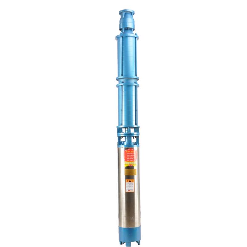
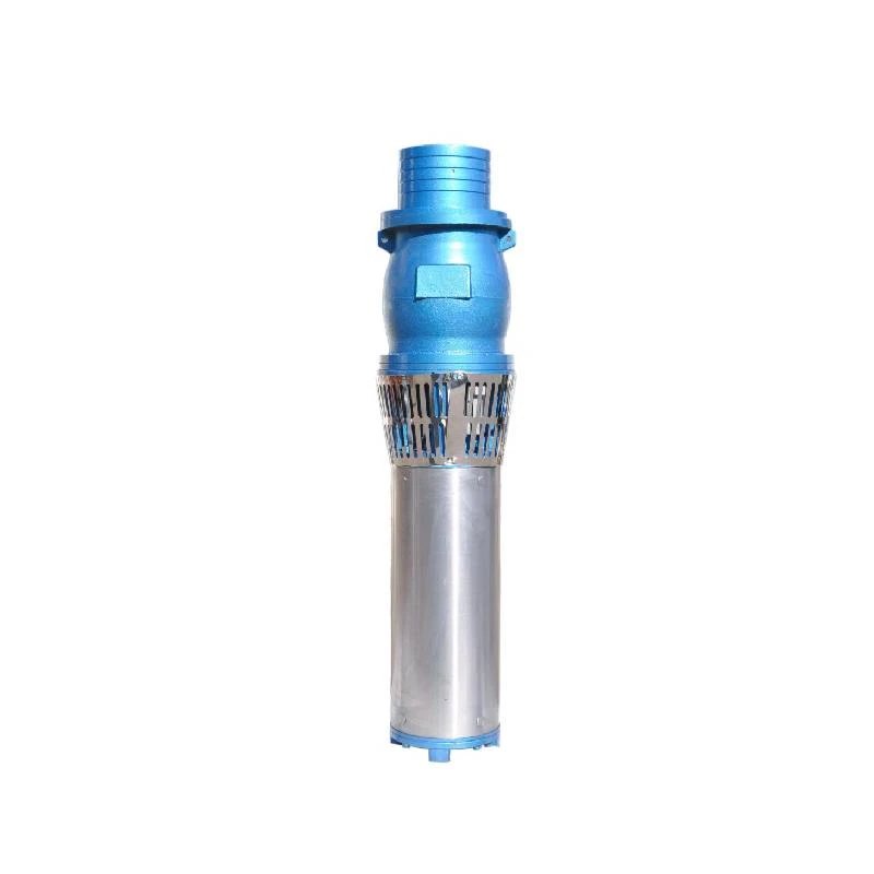
A submersible pump is a type of pump that is submerged in the fluid that is being pumped. Unlike other pumps that pull water (or liquids) from above the surface, a submersible pump is pushed to the surface from below. This type of design allows for greater efficiency and prevents issues like cavitation that can occur in conventional pumps. Submersible pumps are commonly used in wells, aquariums, and even sewage systems.
Importance of the Wiring Diagram
The wiring diagram for a submersible pump is essential for several reasons
1. Safe Installation Working with electricity can be dangerous, especially when dealing with water. A detailed wiring diagram helps ensure that all connections are made correctly, reducing the risk of short circuits or electrocution.
2. Troubleshooting If a pump fails to operate as expected, the wiring diagram serves as a valuable tool for troubleshooting. It allows you to trace connections and identify any potential faults in the wiring.
3. System Integration Many submersible pumps are part of larger systems that include sensors, control panels, and other components. A wiring diagram illustrates how the pump integrates with these elements, helping to facilitate proper communication and functionality.
Key Components in the Wiring Diagram
When examining a typical wiring diagram for a 2% wire submersible pump, several key components are usually identified
- Power Source This is where the electrical supply originates, typically connected to a circuit breaker for safety.
2 wire submersible pump wiring diagram

- Control Switch Some systems utilize a control switch to turn the pump on and off. Depending on the setup, this may involve a float switch or timer.
- Motor Leads The wiring diagram will specify the connections for the pump's motor, usually indicating color codes for the wires—typically black (or brown) for the live wire, white (or blue) for the neutral, and green (or yellow-green) for the ground.
- Capacitor Some submersible pumps require a capacitor for starting. The wiring diagram will show how the capacitor should be connected between the power source and motor.
- Protection Device Circuit breakers or fuses are essential components that prevent overloading of the pump motor.
Wiring Principles
When wiring a submersible pump, there are a few important principles to keep in mind
- Correct Voltage Ensure that the pump is rated for the electrical supply voltage. A mismatch can lead to motor damage.
- Wire Gauge The correct wire gauge is critical. A 2% wire, typically indicating the use of two percent of the full-load capacity of the wire, should be chosen based on the distance from the power source to the pump to minimize voltage drop.
- Sealing Connections Electrical connections must be properly sealed and waterproofed to prevent moisture ingress, which could lead to electrical failure.
Conclusion
A wiring diagram for a 2% wire submersible pump is an essential tool for anyone looking to install or maintain such a pump. It provides clear guidance on how to connect the pump to its power source while ensuring safety and efficiency throughout the operation. By understanding each component and adhering to wiring principles, users can minimize risks and maximize the performance of their submersible pump systems. Whether you are a DIY enthusiast or a professional installer, having a solid grasp of these diagrams will lead to successful installations and trouble-free maintenance.
-
Submersible Water Pump: The Efficient 'Power Pioneer' of the Underwater World
NewsJul.01,2025
-
Submersible Pond Pump: The Hidden Guardian of Water Landscape Ecology
NewsJul.01,2025
-
Stainless Well Pump: A Reliable and Durable Pumping Main Force
NewsJul.01,2025
-
Stainless Steel Submersible Pump: An Efficient and Versatile Tool for Underwater Operations
NewsJul.01,2025
-
Deep Well Submersible Pump: An Efficient 'Sucker' of Groundwater Sources
NewsJul.01,2025
-
Deep Water Well Pump: An Efficient 'Sucker' of Groundwater Sources
NewsJul.01,2025
-
 Submersible Water Pump: The Efficient 'Power Pioneer' of the Underwater WorldIn the field of hydraulic equipment, the Submersible Water Pump has become the core equipment for underwater operations and water resource transportation due to its unique design and excellent performance.Detail
 -
 Submersible Pond Pump: The Hidden Guardian of Water Landscape EcologyIn courtyard landscapes, ecological ponds, and even small-scale water conservancy projects, there is a silent yet indispensable equipment - the Submersible Pond Pump.Detail
 -
 Stainless Well Pump: A Reliable and Durable Pumping Main ForceIn the field of water resource transportation, Stainless Well Pump has become the core equipment for various pumping scenarios with its excellent performance and reliable quality.Detail
