dec . 18, 2024 20:05 Back to list
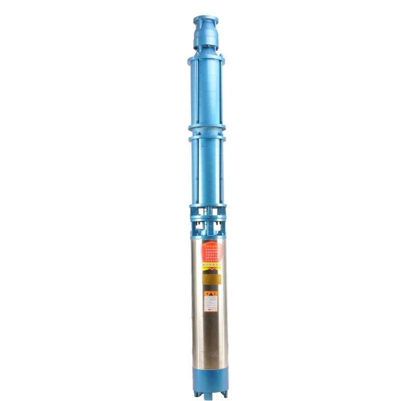
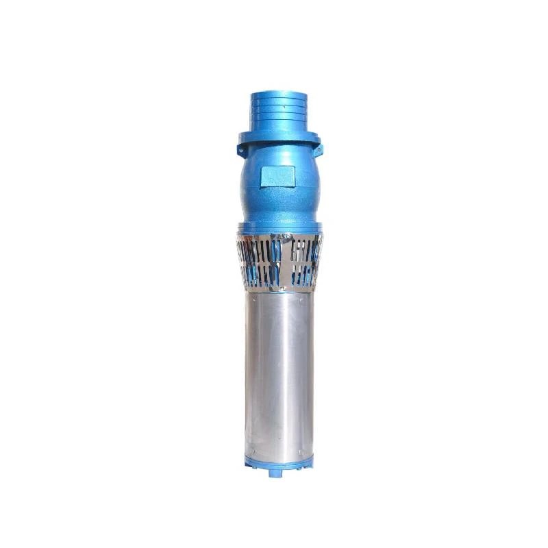
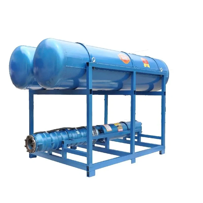
submersible pump drawing
Understanding Submersible Pump Drawings A Comprehensive Guide
Submersible pumps are devices designed to operate while submerged in fluid. They are widely utilized in various applications such as dewatering, sewage treatments, and agricultural irrigation. The functionality and efficiency of these pumps heavily depend on their design, which is encapsulated in technical drawings. This article will delve into the importance of submersible pump drawings, the key components they represent, and how to interpret them effectively.
Importance of Submersible Pump Drawings
Submersible pump drawings are critical for engineers, manufacturers, and technicians. They serve several purposes
1. Design Communication These drawings provide a clear representation of the pump's specifications, including dimensions, materials, and component arrangements. This clarity helps ensure that every stakeholder understands the design intent.
2. Manufacturing Blueprint For manufacturers, these drawings act as blueprints. They outline the manufacturing process, allowing production teams to create the pump accurately according to the desired specifications.
3. Assembly Instructions Submersible pump drawings often include assembly instructions, which guide technicians in putting together the various components of the pump. These instructions help prevent errors during assembly, ensuring the pump operates correctly.
4. Maintenance and Repair Guidance For maintenance technicians, these drawings serve as a reference for troubleshooting and repairing pumps. Understanding the layout of the components can significantly expedite the maintenance process, minimizing downtime.
Key Components Represented in Drawings
When reviewing submersible pump drawings, it’s essential to be familiar with the key components depicted. Here are some of the most critical elements
1. Pump Body and Housing The external shell of the pump that protects internal components from external elements. The material of construction, such as stainless steel or thermoplastic, is often noted.
2. Impeller This rotating component is responsible for moving fluid through the pump. Drawings typically identify the number of vanes, their design, and materials used for enhanced efficiency.
3. Motor In submersible pumps, the motor is usually sealed within the pump body to prevent water ingress. Drawings specify motor specifications, including horsepower, voltage rating, and type of motor (e.g., single-phase vs. three-phase).
submersible pump drawing

4. Suction and Discharge Ports These are crucial for the intake and expulsion of fluid. Drawings provide the dimensions and angles necessary for piping connections.
5. Seal and Bearing Systems To prevent leaks and ensure smooth operation, the details of seals and bearings are meticulously outlined. This includes the type of seals (e.g., mechanical seals) and their arrangement.
6. Control Panel Configuration Some submersible pumps come with integrated control panels which are depicted in the drawings. These panels manage the pump's operation, safety features, and performance monitoring.
How to Interpret Submersible Pump Drawings
Interpreting submersible pump drawings requires understanding the symbols, annotations, and scales used. Here are some tips
1. Familiarize Yourself with Symbols Learn common hydraulic symbols used in pump diagrams. Understanding these symbols is crucial for deciphering how components interact.
2. Check the Scale Drawings may not always be to scale. Ensure you know the ratio used, especially when it comes to sizing connections and determining the spatial arrangement of components.
3. Review Annotations These often provide essential details about materials, dimensions, and tolerances. Reading these thoroughly will give you insights into the quality and specifications required in manufacturing.
4. Cross-Reference Sections Often, submersible pump drawings contain sectional views that provide a cut-through of the pump for a better understanding of the internal component arrangement.
5. Consult with Engineers When in doubt, discussing the drawings with design engineers can clarify intentions and technical specifications, especially for complex designs.
Conclusion
Submersible pump drawings are indispensable tools that encapsulate vital information regarding the design, manufacturing, and maintenance of pumps. By understanding the importance of these drawings and familiarizing yourself with their components and interpretations, you can optimize your engagement with submersible pump systems, ultimately leading to improved efficiency and reliability in fluid management applications. Whether you are an engineer, a manufacturer, or a technician, mastering the language of submersible pump drawings will enhance your ability to contribute effectively to various projects.
-
Submersible Water Pump: The Efficient 'Power Pioneer' of the Underwater World
NewsJul.01,2025
-
Submersible Pond Pump: The Hidden Guardian of Water Landscape Ecology
NewsJul.01,2025
-
Stainless Well Pump: A Reliable and Durable Pumping Main Force
NewsJul.01,2025
-
Stainless Steel Submersible Pump: An Efficient and Versatile Tool for Underwater Operations
NewsJul.01,2025
-
Deep Well Submersible Pump: An Efficient 'Sucker' of Groundwater Sources
NewsJul.01,2025
-
Deep Water Well Pump: An Efficient 'Sucker' of Groundwater Sources
NewsJul.01,2025
-
 Submersible Water Pump: The Efficient 'Power Pioneer' of the Underwater WorldIn the field of hydraulic equipment, the Submersible Water Pump has become the core equipment for underwater operations and water resource transportation due to its unique design and excellent performance.Detail
 -
 Submersible Pond Pump: The Hidden Guardian of Water Landscape EcologyIn courtyard landscapes, ecological ponds, and even small-scale water conservancy projects, there is a silent yet indispensable equipment - the Submersible Pond Pump.Detail
 -
 Stainless Well Pump: A Reliable and Durable Pumping Main ForceIn the field of water resource transportation, Stainless Well Pump has become the core equipment for various pumping scenarios with its excellent performance and reliable quality.Detail
