វិច្ឆិកា . 21, 2024 08:02 Back to list
submersible pump connection diagram
Understanding Submersible Pump Connection Diagrams
Submersible pumps are vital components in various applications, including industrial, agricultural, and domestic uses. These pumps operate underwater, making them efficient for moving water and other fluids from deep within boreholes, wells, or tanks. Understanding the connection diagram of a submersible pump is crucial for installation, operation, and maintenance. This article will delve into the key aspects of submersible pump connection diagrams, helping users comprehend their structure and function.
The Importance of Connection Diagrams
Submersible pump connection diagrams serve multiple purposes. First and foremost, they provide a visual representation of the pump's electrical and hydraulic connections. This information is essential for technicians and engineers during the installation phase, ensuring that all components are connected correctly to prevent operational failures. Additionally, these diagrams facilitate troubleshooting and maintenance processes by outlining how different parts interact within the system.
Key Components Illustrated in the Diagram
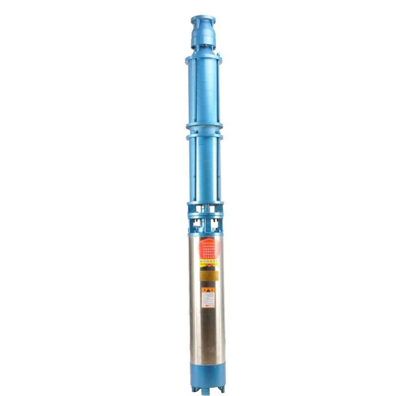
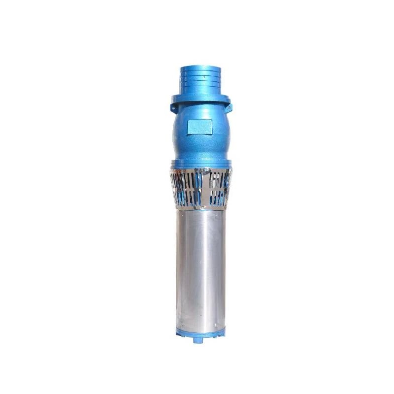
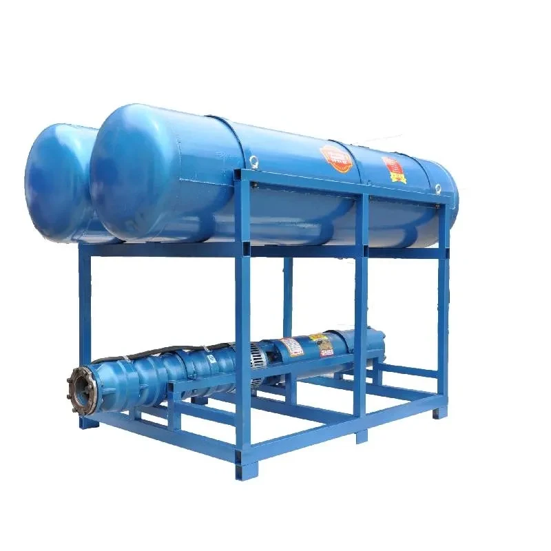
1. Pump and Motor At the heart of any submersible pump system is the pump itself, which is usually coupled with an electric motor. The connection diagram shows how the motor powers the pump to effectively draw water or fluid from its source.
2. Control Panel The control panel is responsible for managing the pump's operation. It contains various switches, meters, and protection devices that monitor and control the pump's performance. Connection diagrams depict how electrical lines travel from the control panel to the pump's motor, facilitating proper operation.
3. Power Supply A reliable power source is crucial for the smooth operation of submersible pumps. Connection diagrams detail how the power supply feeds into the pump system, including the voltage specifications and the type of wiring used.
4. Sensors and Switches Many submersible pumps are equipped with sensors and switches, such as pressure sensors and float switches, which play significant roles in automating the pump’s operations. These components help detect fluid levels and pressure fluctuations, sending signals to the control panel to start or stop the pump as needed.
submersible pump connection diagram

5. Discharge Pipe The pathway through which fluids are discharged from the pump is illustrated in the connection diagram. Understanding the discharge pipe's configuration is essential for ensuring the proper flow rate and pressure in the system.
6. Grounding Safety is a significant concern when dealing with electrical components submerged in water. Connection diagrams highlight the importance of grounding to prevent electrical shocks and ensure the stable operation of the pump.
Tips for Reading Connection Diagrams
1. Familiarize Yourself with Symbols Different components are represented by specific symbols in connection diagrams. Understanding these symbols is essential for interpreting the overall layout and function of the pump system.
2. Follow the Flow of Energy and Fluid Tracking how energy flows from the power source through the control panel to the motor, and how the fluid moves through the pump and discharge pipe, will help you understand the system's operation.
3. Check Color Codes Wiring in the diagram may use color codes to indicate different functions (e.g., live, neutral, and ground wires). Be aware of these codes when installing or troubleshooting the pump.
4. Refer to Manufacturer Manuals Always cross-reference the connection diagram with the manufacturer’s manual specific to your pump model. Each model might have unique characteristics that require special attention.
Conclusion
Understanding the connection diagram of a submersible pump is essential for anyone involved in its installation, operation, and maintenance. By familiarizing oneself with the various components, electrical connections, and operational processes illustrated in these diagrams, users can ensure the reliable and efficient functioning of submersible pumps. This knowledge not only aids in troubleshooting but also helps maintain safety standards essential for working with submersible systems in potentially hazardous environments.
-
Submersible Water Pump: The Efficient 'Power Pioneer' of the Underwater World
NewsJul.01,2025
-
Submersible Pond Pump: The Hidden Guardian of Water Landscape Ecology
NewsJul.01,2025
-
Stainless Well Pump: A Reliable and Durable Pumping Main Force
NewsJul.01,2025
-
Stainless Steel Submersible Pump: An Efficient and Versatile Tool for Underwater Operations
NewsJul.01,2025
-
Deep Well Submersible Pump: An Efficient 'Sucker' of Groundwater Sources
NewsJul.01,2025
-
Deep Water Well Pump: An Efficient 'Sucker' of Groundwater Sources
NewsJul.01,2025
-
 Submersible Water Pump: The Efficient 'Power Pioneer' of the Underwater WorldIn the field of hydraulic equipment, the Submersible Water Pump has become the core equipment for underwater operations and water resource transportation due to its unique design and excellent performance.Detail
 -
 Submersible Pond Pump: The Hidden Guardian of Water Landscape EcologyIn courtyard landscapes, ecological ponds, and even small-scale water conservancy projects, there is a silent yet indispensable equipment - the Submersible Pond Pump.Detail
 -
 Stainless Well Pump: A Reliable and Durable Pumping Main ForceIn the field of water resource transportation, Stainless Well Pump has become the core equipment for various pumping scenarios with its excellent performance and reliable quality.Detail
