
Feb . 14, 2025 04:19 Back to list
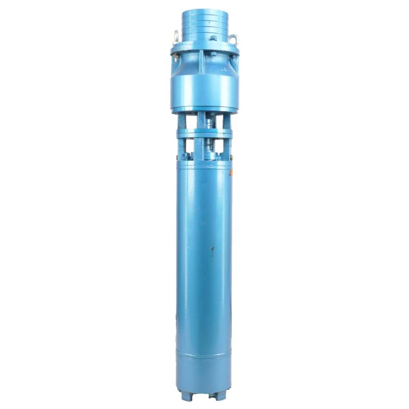
deep well submersible pump installation diagram
A submersible pump is a marvel of modern engineering, designed to operate while being completely submerged in water. Essential for various applications such as draining flooded basements, irrigating fields, and even powering fountains, understanding its design is crucial for both users and technicians. This article delves into the intricacies of the submersible pump diagram, shedding light on its components and the science behind its operation.
A pressure sensor and float switch are components that add to the pump's automatic operation feature, as seen in advanced submersible pump models. The pressure sensor activates the pump based on water pressure, while the float switch automates the pump's on-off cycle depending on water level. These components ensure energy efficiency and reduce the risk of damage from dry running. The electrical cable, another essential component detailed in the diagram, must be robust and insulated to prevent electrical hazards. The choice of material and the cable's routing within the pump assembly determine the pump's safety and operational lifespan. Properly labeled diagrams often indicate voltage and amperage requirements, critical information for safe and effective installation. Another important aspect not to overlook in a submersible pump diagram is the check valve. Installed on the discharge pipe, this valve prevents backflow into the pump housing. A check valve's role is crucial in maintaining the pump's priming and preventing possible damage caused by reverse flow. The orientation and specification of the valve in the diagram provide insights into how the pump handles varying operational demands. Manufacturers provide submersible pump diagrams to ensure proper installation and maintenance. These diagrams serve as a guide, offering an authoritative overview of the pump's internal workings, and are indispensable for troubleshooting. They also reinforce the credibility manufacturers have concerning their products' reliability and performance. In summary, a comprehensive understanding of a submersible pump diagram is not just for engineers or technicians but for anyone interested in utilizing these powerful devices. Each component, from the motor to the seals, plays a role in the pump’s effectiveness and longevity. A well-interpreted diagram empowers users, enabling them to make informed decisions about purchase, installation, and maintenance, ensuring prolonged service and optimal performance from their investment. Understanding the diagram's insights is vital for ensuring that the submersible pump meets the demands of its intended application while operating with maximum efficiency and minimal environmental impact.
A pressure sensor and float switch are components that add to the pump's automatic operation feature, as seen in advanced submersible pump models. The pressure sensor activates the pump based on water pressure, while the float switch automates the pump's on-off cycle depending on water level. These components ensure energy efficiency and reduce the risk of damage from dry running. The electrical cable, another essential component detailed in the diagram, must be robust and insulated to prevent electrical hazards. The choice of material and the cable's routing within the pump assembly determine the pump's safety and operational lifespan. Properly labeled diagrams often indicate voltage and amperage requirements, critical information for safe and effective installation. Another important aspect not to overlook in a submersible pump diagram is the check valve. Installed on the discharge pipe, this valve prevents backflow into the pump housing. A check valve's role is crucial in maintaining the pump's priming and preventing possible damage caused by reverse flow. The orientation and specification of the valve in the diagram provide insights into how the pump handles varying operational demands. Manufacturers provide submersible pump diagrams to ensure proper installation and maintenance. These diagrams serve as a guide, offering an authoritative overview of the pump's internal workings, and are indispensable for troubleshooting. They also reinforce the credibility manufacturers have concerning their products' reliability and performance. In summary, a comprehensive understanding of a submersible pump diagram is not just for engineers or technicians but for anyone interested in utilizing these powerful devices. Each component, from the motor to the seals, plays a role in the pump’s effectiveness and longevity. A well-interpreted diagram empowers users, enabling them to make informed decisions about purchase, installation, and maintenance, ensuring prolonged service and optimal performance from their investment. Understanding the diagram's insights is vital for ensuring that the submersible pump meets the demands of its intended application while operating with maximum efficiency and minimal environmental impact.
Latest news
-
Understanding the Price Submersible Pump and Buyer Guide
NewsApr.16,2026
-
Factors Affecting the Price for Submersible Pump a Buyers Guide
NewsApr.09,2026
-
Choosing the Right Mini Submersible Fountain Pump for Optimal Water Feature Performance
NewsApr.07,2026
-
A Detailed Guide to Installing a Submersible Pump for Optimal Performance
NewsApr.04,2026
-
Comprehensive Guide on How to Test a Submersible Water Well Pump Effectively
NewsMar.31,2026
-
Learn How to Replace a Submersible Well Pump Safely and Effectively
NewsMar.28,2026
-
 Understanding the Price Submersible Pump and Buyer GuideWhen searching for the ideal water management solution, understanding the price submersible pump options is crucial for balancing budget with performance. Whether you are dealing with a flooded basement, managing agricultural irrigation, or extracting water from a deep well, the cost of a submersible pump can vary significantly based on its build quality and capacity. Investing in a high-quality pump ensures long-term reliability and reduces the frequency of expensive replacements. In this guide, we will break down the factors that influence pricing and help you make an informed decision for your specific needs.Detail
 -
 Factors Affecting the Price for Submersible Pump a Buyers GuideWhen investing in water management systems, understanding the price for submersible pump options is essential for balancing performance with budget. Whether you are managing a residential well, an industrial drainage project, or agricultural irrigation, the cost of a pump is rarely a flat fee; it is a reflection of the engineering, materials, and capacity required for your specific environment. In this guide, we will break down the factors that influence pricing and help you determine the best value for your investment to ensure long-term reliability and efficiency.Detail
 -
 Choosing the Right Mini Submersible Fountain Pump for Optimal Water Feature PerformanceCreating a beautiful and relaxing water feature doesn't have to be complicated. A mini submersible fountain pump is the heart of any indoor or outdoor fountain, and selecting the right one is crucial for optimal performance and longevity. This article will guide you through the key considerations when choosing a mini submersible fountain pump, covering types, features, applications, and how to ensure you get the perfect pump for your project. We’ll also explore how Wellpumpact can provide you with the ideal solution.Detail