Nov . 10, 2024 23:14 Back to list
Wiring Guide for 4 Inch Submersible Pump Installation and Connection
Understanding the Wiring Diagram for a 4% Wire Submersible Pump
Submersible pumps are widely used in various applications, from residential water supply systems to agricultural irrigation and industrial processes. One essential aspect of installing and maintaining these pumps is understanding their wiring diagrams. This article will provide a comprehensive overview of the wiring diagram for a typical 4-wire submersible pump, highlighting the components involved, their functions, and basic troubleshooting tips.
Components of a 4-Wire Submersible Pump
A standard 4-wire submersible pump setup typically includes the following components
1. Submersible Pump This pump is designed to operate underwater, and its motor is sealed to prevent water ingress.
2. Electrical Wire The four wires in the configuration usually consist of two for power supply (typically hot wires) and two for control (a common wire and a ground wire).
3. Control Box This is often located above ground and houses the necessary electrical components for controlling the pump. It usually contains a contactor, overload relay, and circuitry for both the power supply and control functions.
4. Circuit Breaker Installed to protect the wiring and the pump motor from overcurrents. It is essential for ensuring safe operation.
5. Power Supply This can be a single-phase or three-phase supply, depending on the pump's specifications.
Understanding the Wiring Diagram
When looking at the wiring diagram for a 4-wire submersible pump, you may notice that the wires are color-coded (commonly black, red, green, and white). Understanding these color codes is crucial
- Black and Red Wires These wires typically represent the power supply. The black wire is often used for the first hot connection, and the red wire serves as the second hot connection. Together, they provide the necessary voltage to the motor.
- White Wire The white wire is usually the neutral or common wire, which completes the electric circuit back to the power supply
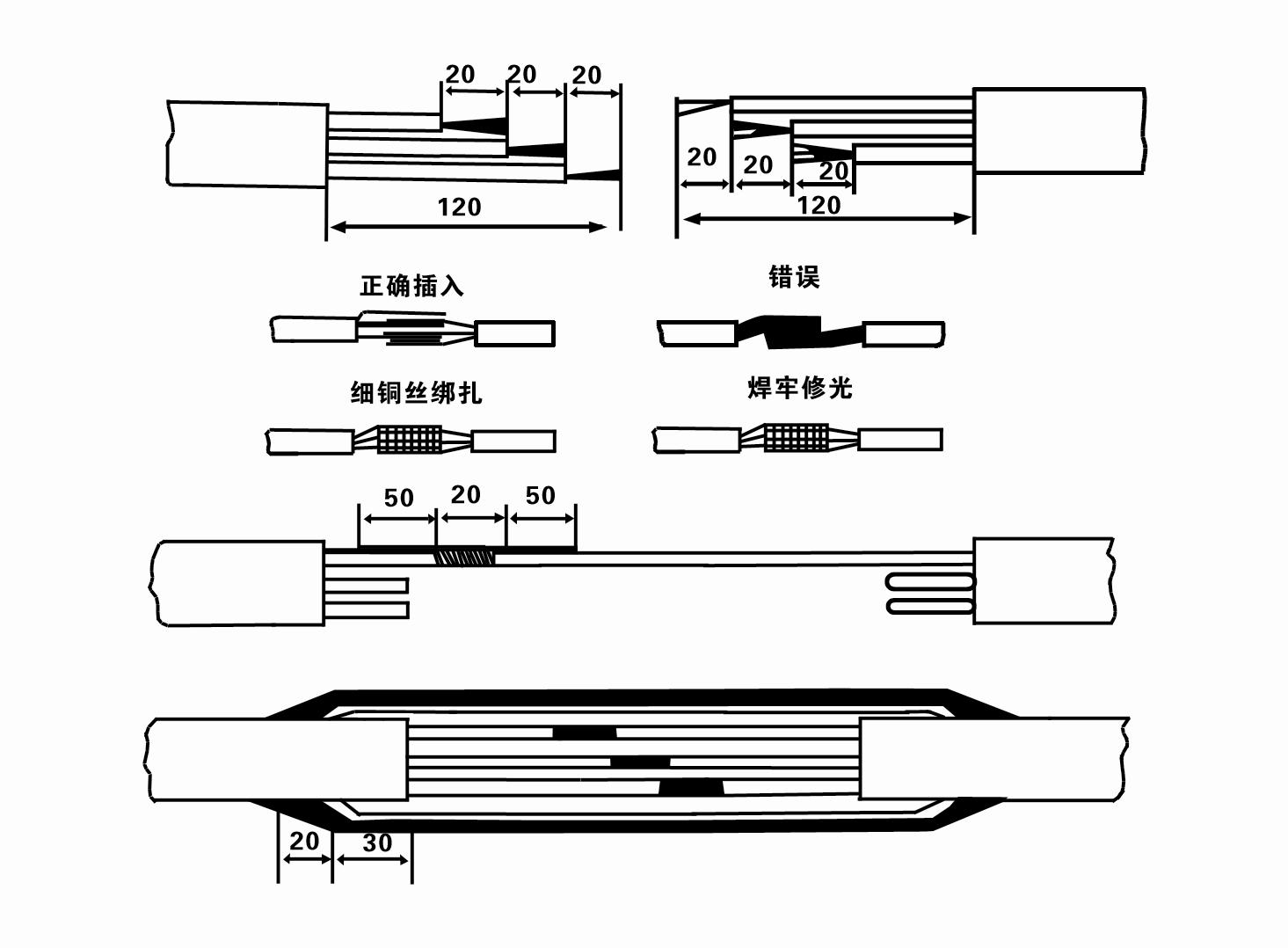
.4 wire submersible pump wiring diagram

- Green Wire This wire usually functions as the ground. It is crucial for safety, as it prevents electrical shocks and other hazards.
Wiring Connections
1. Connecting the Pump The black and red wires from the pump connect to the corresponding terminals in the control box. The neutral wire (white) connects back to the power supply, while the green wire connects to the grounding point.
2. Contactor Wiring Within the control box, the contactor plays a critical role in regulating power to the pump. The wiring diagram will show how the power lines connect to the contactor and how it interfaces with the control switch.
3. Safety Precautions Always ensure that you switch off the power supply before attempting any wiring. Use appropriate personal protective equipment and follow local electrical codes to ensure safety.
Troubleshooting Tips
Understanding the wiring diagram can also help in troubleshooting common issues
- Pump Not Working If the pump doesn’t start, check the circuit breaker and the connections within the control box. Ensure that all wires are securely connected and free from damage.
- Overheating If the pump is overheating, it may indicate an electrical overload. Inspect the wiring for signs of wear or insulation damage, and verify that the circuit isn’t overloaded.
- Erratic Performance If the pump runs intermittently, the issue could be a faulty contactor or loose wiring. Examine the connections and replace any damaged components as necessary.
Conclusion
A clear understanding of the wiring diagram for a 4-wire submersible pump not only facilitates proper installation but also aids in maintenance and troubleshooting. By recognizing the roles of each wire and component involved in the system, users can ensure their submersible pump operates efficiently and safely over its operational lifespan. Always consult with a professional if unsure, as safety should be the top priority in any electrical system.
-
Submersible Water Pump: The Efficient 'Power Pioneer' of the Underwater World
NewsJul.01,2025
-
Submersible Pond Pump: The Hidden Guardian of Water Landscape Ecology
NewsJul.01,2025
-
Stainless Well Pump: A Reliable and Durable Pumping Main Force
NewsJul.01,2025
-
Stainless Steel Submersible Pump: An Efficient and Versatile Tool for Underwater Operations
NewsJul.01,2025
-
Deep Well Submersible Pump: An Efficient 'Sucker' of Groundwater Sources
NewsJul.01,2025
-
Deep Water Well Pump: An Efficient 'Sucker' of Groundwater Sources
NewsJul.01,2025
-
 Submersible Water Pump: The Efficient 'Power Pioneer' of the Underwater WorldIn the field of hydraulic equipment, the Submersible Water Pump has become the core equipment for underwater operations and water resource transportation due to its unique design and excellent performance.Detail
 -
 Submersible Pond Pump: The Hidden Guardian of Water Landscape EcologyIn courtyard landscapes, ecological ponds, and even small-scale water conservancy projects, there is a silent yet indispensable equipment - the Submersible Pond Pump.Detail
 -
 Stainless Well Pump: A Reliable and Durable Pumping Main ForceIn the field of water resource transportation, Stainless Well Pump has become the core equipment for various pumping scenarios with its excellent performance and reliable quality.Detail
