Sep . 03, 2024 00:48 Back to list
deep well pump installation diagram
Understanding the Deep Well Pump Installation Diagram
Installing a deep well pump can seem daunting, but understanding the installation diagram is the first step toward ensuring a successful setup. Deep well pumps are designed to extract water from deep underground aquifers, which is essential for agricultural, residential, and industrial water supply. This article will break down the key components and processes as depicted in a typical deep well pump installation diagram.
Key Components of the Installation Diagram
1. Well Casing The installation begins with the well casing, which is a vital structure that prevents contaminants from entering the well. Typically made of steel or PVC, the casing is installed to a specified depth and helps maintain the integrity of the well.
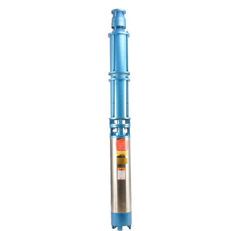
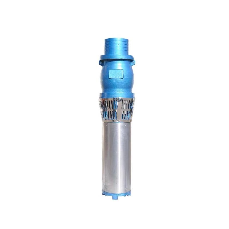
2. Pump and Motor The heart of the system—the pump—is usually submerged in water at the bottom of the well. It's essential to select the right size and type of pump based on the required flow rate and depth of the water level. The motor, often located above ground, powers the pump.
3. Drop Pipe Connecting the pump to the surface is the drop pipe, which is a vertical pipe that transports the water pumped up to the surface. The diameter and material of this pipe should be chosen carefully to minimize friction loss and ensure efficient water flow.
4. Discharge Head At the top of the well, the discharge head is where water exits the well system and is routed to its final destination. This component also supports the pump and motor while providing access for maintenance.
5. Electrical Components The installation diagram will include wiring details for the motor, which typically requires specific sizing and insulation to handle the electrical load. A control panel may also be indicated, featuring on/off switches and safety alarms.
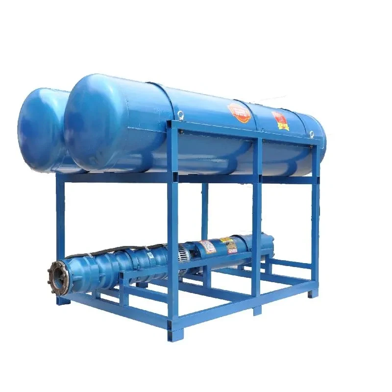
6. Pressure Tank Often included in the system, a pressure tank helps maintain water pressure and reduces the cycling of the pump. This component is vital for providing a steady water supply and avoiding wear and tear on the pump.
7. Check Valve A check valve is an essential safety feature, preventing backflow when the pump is off. Its placement in the installation diagram ensures that water only flows in one direction—toward the surface.
Installation Process
deep well pump installation diagram

Understanding the diagram is crucial for proper installation
. Here’s a simplified overview of the installation process1. Site Assessment Choosing the correct location for the well is a crucial first step. Consider proximity to water sources and the quality of the aquifer.
2. Drilling the Well Once the site is assessed, drilling is performed. The depth of the well depends on the water table level and the specific needs of the user.
3. Installing the Casing After drilling, the well casing is installed to protect the well from external contaminants.
4. Setting Up the Pump and Drop Pipe The submersible pump is connected to the drop pipe and lowered into the well. This is a critical phase where care should be taken to prevent damage to the equipment.
5. Electrical Hookups Once the pump is in place, the electrical connections are made following the schematic guidelines in the installation diagram.
6. Testing the System After installation, the entire system must be tested for leaks and operational functionality. The pump's performance should meet the expected flow rates.
7. Regular Maintenance Finally, understanding maintenance needs is essential for long-term functionality. Regular checks can help detect issues early.
Conclusion
A deep well pump installation diagram provides crucial information for successfully installing a pumping system. By understanding each component and the overall installation process, individuals and professionals can ensure efficient and reliable access to groundwater, crucial for various applications. Proper installation and maintenance will lead to longer pump life and better water management in the long run.
-
Submersible Water Pump: The Efficient 'Power Pioneer' of the Underwater World
NewsJul.01,2025
-
Submersible Pond Pump: The Hidden Guardian of Water Landscape Ecology
NewsJul.01,2025
-
Stainless Well Pump: A Reliable and Durable Pumping Main Force
NewsJul.01,2025
-
Stainless Steel Submersible Pump: An Efficient and Versatile Tool for Underwater Operations
NewsJul.01,2025
-
Deep Well Submersible Pump: An Efficient 'Sucker' of Groundwater Sources
NewsJul.01,2025
-
Deep Water Well Pump: An Efficient 'Sucker' of Groundwater Sources
NewsJul.01,2025
-
 Submersible Water Pump: The Efficient 'Power Pioneer' of the Underwater WorldIn the field of hydraulic equipment, the Submersible Water Pump has become the core equipment for underwater operations and water resource transportation due to its unique design and excellent performance.Detail
 -
 Submersible Pond Pump: The Hidden Guardian of Water Landscape EcologyIn courtyard landscapes, ecological ponds, and even small-scale water conservancy projects, there is a silent yet indispensable equipment - the Submersible Pond Pump.Detail
 -
 Stainless Well Pump: A Reliable and Durable Pumping Main ForceIn the field of water resource transportation, Stainless Well Pump has become the core equipment for various pumping scenarios with its excellent performance and reliable quality.Detail
