Aug . 30, 2024 03:23 Back to list
Diagram of Submersible Well Pump
Understanding Submersible Well Pumps A Diagrammatic Insight
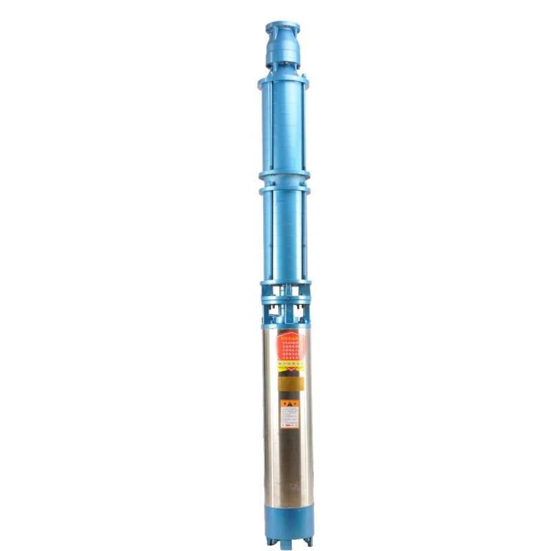
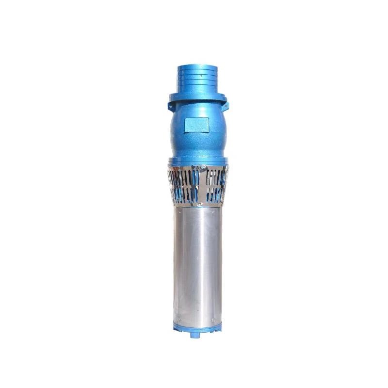
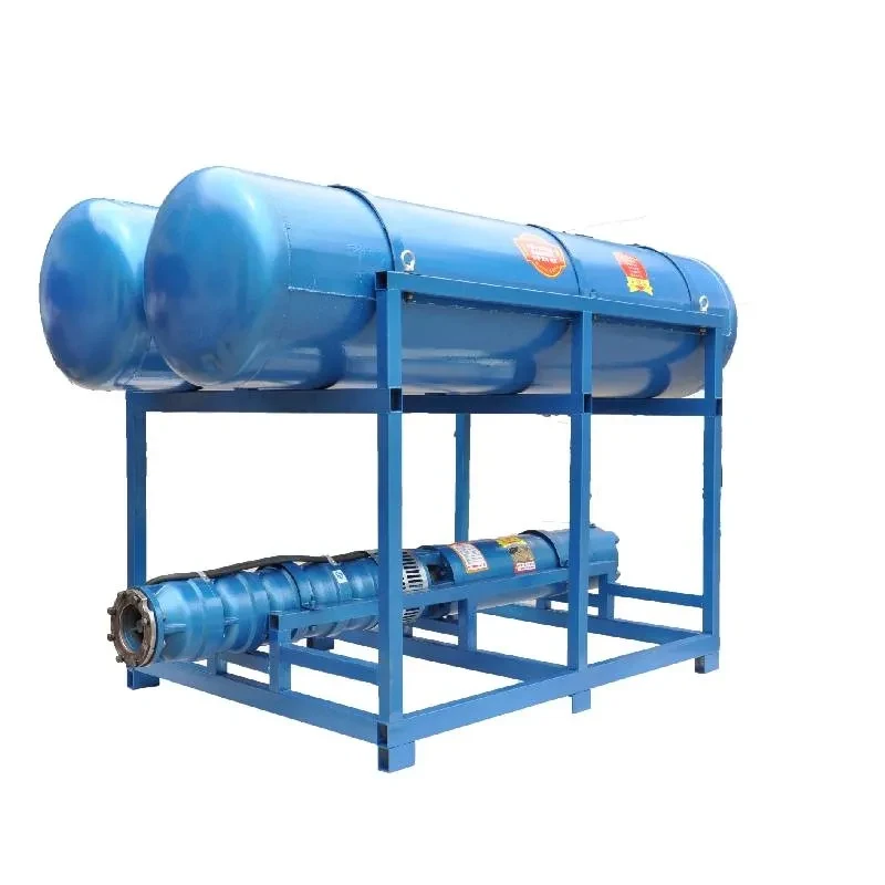
Submersible well pumps are vital components in many water supply systems, especially in areas where groundwater extraction is necessary. These pumps are designed to operate underwater, pushing water to the surface, and are extensively utilized in agriculture, municipal water supply, and industrial applications. A clear understanding of their design and function can be achieved through a detailed examination of their diagram.
Understanding Submersible Well Pumps A Diagrammatic Insight
The pump itself consists of stages, typically made of corrosion-resistant materials. Water enters the pump through intake screens designed to prevent debris from clogging the system. Each stage consists of an impeller and a diffuser, working in tandem to maintain an optimal flow rate, which is crucial for meeting the demands of the water supply system. The more stages a submersible pump has, the greater the lift capacity, making it suitable for deeper wells.
diagram of submersible well pump

An essential feature depicted in the diagram is the discharge head, located at the surface level of the well. This component serves multiple functions; it supports the pump, provides an outlet for the water, and often includes a check valve to prevent backflow. Some discharge heads are also equipped with pressure gauges that provide real-time feedback on the system’s performance, ensuring that operators can monitor the water pressure and adjust settings as necessary.
The protective casing surrounding the pump is critical for operational safety and longevity. This casing, usually made of durable steel or polyethylene, protects the pump from environmental hazards and provides structural integrity during installation and operation. Additionally, the cable entry point is illustrated in the diagram, showing how electrical power is delivered to the motor. Ensuring the sealing of these cable entry points is crucial to prevent water ingress, which could lead to pump failure.
Another aspect worth mentioning, often shown in detailed diagrams, is the float switch mechanism. This device automatically controls the operation of the pump based on water levels, preventing dry running and potential damage to the pump. This automation adds an element of convenience and safety to the system, allowing for continuous monitoring without constant human intervention.
In conclusion, the diagram of a submersible well pump serves as a valuable tool for understanding how these systems operate. From the motor to the discharge head, each component plays a crucial role in ensuring efficient water extraction. As demand for groundwater increases, understanding the complexities of submersible well pumps becomes ever more important for sustainable water management.
-
Submersible Water Pump: The Efficient 'Power Pioneer' of the Underwater World
NewsJul.01,2025
-
Submersible Pond Pump: The Hidden Guardian of Water Landscape Ecology
NewsJul.01,2025
-
Stainless Well Pump: A Reliable and Durable Pumping Main Force
NewsJul.01,2025
-
Stainless Steel Submersible Pump: An Efficient and Versatile Tool for Underwater Operations
NewsJul.01,2025
-
Deep Well Submersible Pump: An Efficient 'Sucker' of Groundwater Sources
NewsJul.01,2025
-
Deep Water Well Pump: An Efficient 'Sucker' of Groundwater Sources
NewsJul.01,2025
-
 Submersible Water Pump: The Efficient 'Power Pioneer' of the Underwater WorldIn the field of hydraulic equipment, the Submersible Water Pump has become the core equipment for underwater operations and water resource transportation due to its unique design and excellent performance.Detail
 -
 Submersible Pond Pump: The Hidden Guardian of Water Landscape EcologyIn courtyard landscapes, ecological ponds, and even small-scale water conservancy projects, there is a silent yet indispensable equipment - the Submersible Pond Pump.Detail
 -
 Stainless Well Pump: A Reliable and Durable Pumping Main ForceIn the field of water resource transportation, Stainless Well Pump has become the core equipment for various pumping scenarios with its excellent performance and reliable quality.Detail
