Oct . 05, 2024 10:43 Back to list
Overview of Submersible Well Pump System Components and Functionality
Understanding Submersible Well Pumps A Diagram Analysis
Submersible well pumps are essential devices used in a variety of applications, from providing irrigation for agricultural fields to supplying freshwater for residential and industrial use
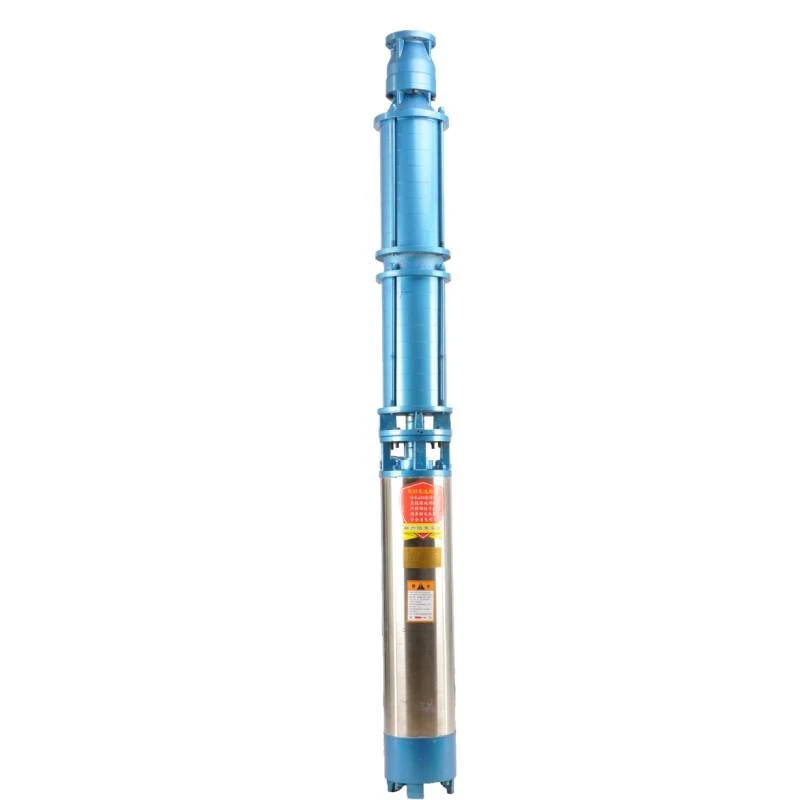
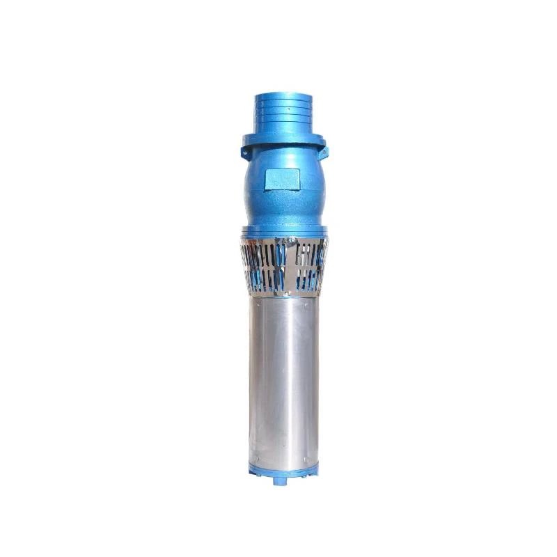
. A thorough understanding of their design and functionality can be greatly enhanced by analyzing a diagram of a submersible well pump.At the core of the submersible pump's structure lies the motor, which is typically positioned at the base of the unit. This motor is hermetically sealed to prevent water intrusion and is often coupled directly to the pump impellers. The design of the motor allows it to operate underwater, reducing noise and the risk of mechanical failure. One of the functional advantages of a submersible pump is that it pushes water to the surface rather than pulling it, which makes it highly effective in deep well applications.
The impeller is another critical component represented in a well pump diagram. It is designed in a spiral or radial pattern to facilitate the movement of water. As the motor spins the impeller, water is drawn in through the intake and is then propelled upward through the pump’s casing. This action generates the necessary pressure to push the water through the discharge pipe.
diagram of submersible well pump

Moving upwards, we reach the discharge head, which is where the processed water exits the pump. The discharge head often includes several features such as a check valve to prevent backflow, and it may sometimes house monitoring equipment to track pressure and flow rates. Understanding these components is crucial for troubleshooting and maintenance.
Another important aspect of the diagram is the power supply line, which provides electricity to the motor. This line must be robust and waterproof, as it must endure harsh underground conditions. Proper installation of this power line is vital to ensure the pump operates smoothly without electrical failures or water ingress.
Furthermore, the diagram might highlight safety features such as overheat protection mechanisms, which prevent the motor from burning out, and the float switch, which helps regulate the water level in the well. These features not only enhance the longevity of the pump but also ensure optimal performance.
In summary, a diagram of a submersible well pump reveals vital information about its components and operational principles. Understanding the interconnections among the motor, impeller, discharge head, and related safety mechanisms is paramount for anyone involved in the installation, maintenance, or operation of these pumps. As water demands continue to rise, the significance of submersible well pumps in both urban and rural settings will undoubtedly grow, making it even more essential to understand their design and function through such illustrative diagrams.
-
Submersible Water Pump: The Efficient 'Power Pioneer' of the Underwater World
NewsJul.01,2025
-
Submersible Pond Pump: The Hidden Guardian of Water Landscape Ecology
NewsJul.01,2025
-
Stainless Well Pump: A Reliable and Durable Pumping Main Force
NewsJul.01,2025
-
Stainless Steel Submersible Pump: An Efficient and Versatile Tool for Underwater Operations
NewsJul.01,2025
-
Deep Well Submersible Pump: An Efficient 'Sucker' of Groundwater Sources
NewsJul.01,2025
-
Deep Water Well Pump: An Efficient 'Sucker' of Groundwater Sources
NewsJul.01,2025
-
 Submersible Water Pump: The Efficient 'Power Pioneer' of the Underwater WorldIn the field of hydraulic equipment, the Submersible Water Pump has become the core equipment for underwater operations and water resource transportation due to its unique design and excellent performance.Detail
 -
 Submersible Pond Pump: The Hidden Guardian of Water Landscape EcologyIn courtyard landscapes, ecological ponds, and even small-scale water conservancy projects, there is a silent yet indispensable equipment - the Submersible Pond Pump.Detail
 -
 Stainless Well Pump: A Reliable and Durable Pumping Main ForceIn the field of water resource transportation, Stainless Well Pump has become the core equipment for various pumping scenarios with its excellent performance and reliable quality.Detail
