Aug . 28, 2024 21:58 Back to list
Submersible Pump Connection Diagram - Comprehensive Guide
Understanding Submersible Pump Connection Diagrams
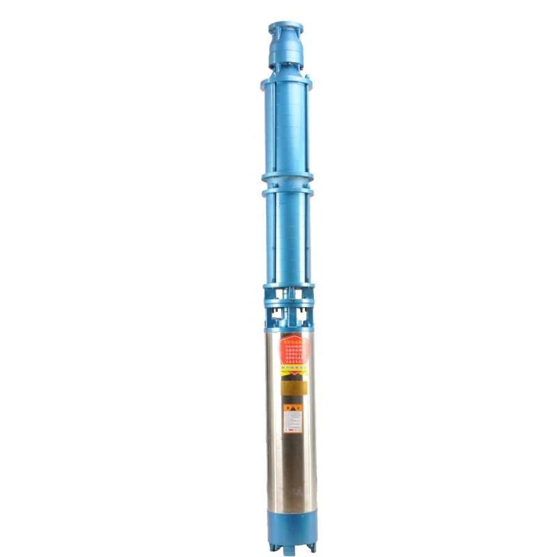
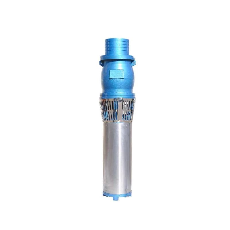
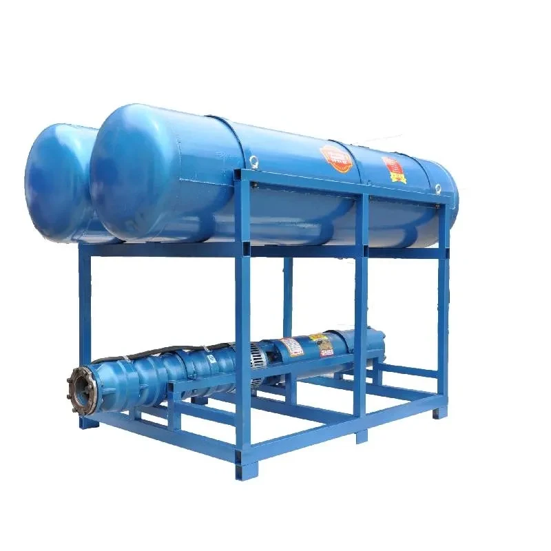
Submersible pumps are critical components used in a variety of applications, including groundwater extraction, wastewater management, and urban drainage systems. To effectively harness the capabilities of these pumps, it’s essential to understand the connection diagrams that accompany them. This article outlines the fundamental elements of submersible pump connection diagrams and their importance in installation and maintenance.
A submersible pump operates by being submerged in the fluid it is intended to pump. The key advantage of this design is its ability to push water to the surface, rather than pulling it, which makes it more efficient and reduces the risk of cavitation. To maximize the efficiency of these devices, a clear understanding of their connection diagrams is crucial.
Typically, a submersible pump connection diagram illustrates several key components. The pump itself, of course, is at the center of the diagram. Surrounding the pump are electrical connections, discharge pipes, and control devices. Proper labeling and organization in these diagrams allow technicians and engineers to understand the configuration quickly.
One of the primary components connected to the submersible pump is the power supply. The diagram outlines how to connect the pump to an electrical source, which may include circuit breakers and relays for safety. Incorrect electrical connections can lead to pump failure or electrical hazards, making it critical to follow the diagram accurately.
submersible pump connection diagram

Next, the diagram usually showcases the discharge line. This part is crucial as it determines how the fluid will be conveyed from the pump to the desired location. The diameter and material of the discharge pipe are often specified, as they directly affect the pump's efficiency and performance. Clear indications of any necessary fittings or valves further aid in creating a reliable system.
Furthermore, control devices such as float switches or pressure switches are depicted within the connection diagram. These devices enable automatic operation of the pump based on water levels or pressure. Understanding where and how to connect these switches is vital for operational efficiency, ensuring that the pump turns on and off as intended.
Lastly, connection diagrams can also include safety features and installation notes. Grounding requirements, safety limits, and inspection points may be detailed to guide installers and maintenance personnel.
In conclusion, a submersible pump connection diagram serves as a vital tool for anyone involved in the installation and maintenance of these systems. By providing a clear visual representation of connections, components, and safety features, these diagrams ensure that submersible pumps are installed correctly, function efficiently, and remain safe over their operational lifespan. Proper interpretation of these diagrams safeguards both the equipment's integrity and the safety of personnel, emphasizing the importance of engineering diagrams in pump operation.
-
Submersible Water Pump: The Efficient 'Power Pioneer' of the Underwater World
NewsJul.01,2025
-
Submersible Pond Pump: The Hidden Guardian of Water Landscape Ecology
NewsJul.01,2025
-
Stainless Well Pump: A Reliable and Durable Pumping Main Force
NewsJul.01,2025
-
Stainless Steel Submersible Pump: An Efficient and Versatile Tool for Underwater Operations
NewsJul.01,2025
-
Deep Well Submersible Pump: An Efficient 'Sucker' of Groundwater Sources
NewsJul.01,2025
-
Deep Water Well Pump: An Efficient 'Sucker' of Groundwater Sources
NewsJul.01,2025
-
 Submersible Water Pump: The Efficient 'Power Pioneer' of the Underwater WorldIn the field of hydraulic equipment, the Submersible Water Pump has become the core equipment for underwater operations and water resource transportation due to its unique design and excellent performance.Detail
 -
 Submersible Pond Pump: The Hidden Guardian of Water Landscape EcologyIn courtyard landscapes, ecological ponds, and even small-scale water conservancy projects, there is a silent yet indispensable equipment - the Submersible Pond Pump.Detail
 -
 Stainless Well Pump: A Reliable and Durable Pumping Main ForceIn the field of water resource transportation, Stainless Well Pump has become the core equipment for various pumping scenarios with its excellent performance and reliable quality.Detail
