Nov . 15, 2024 13:23 Back to list
submersible pump connection diagram
Understanding Submersible Pump Connection Diagrams
Submersible pumps are vital components in various industrial and residential applications, primarily used for pumping water from wells, basements, and sewage systems. Their ability to operate underwater makes them unique compared to other pumps, and understanding their connection diagrams is crucial for effective installation and maintenance.
A submersible pump connection diagram typically illustrates the electrical and hydraulic connections within the pump system. It serves as a roadmap for technicians and engineers when wiring the pump, ensuring that all components are appropriately connected for reliable operation. A well-designed connection diagram will often include various key elements, including the pump itself, electrical supply, control panel, and safety devices.
The Pump and Its Components
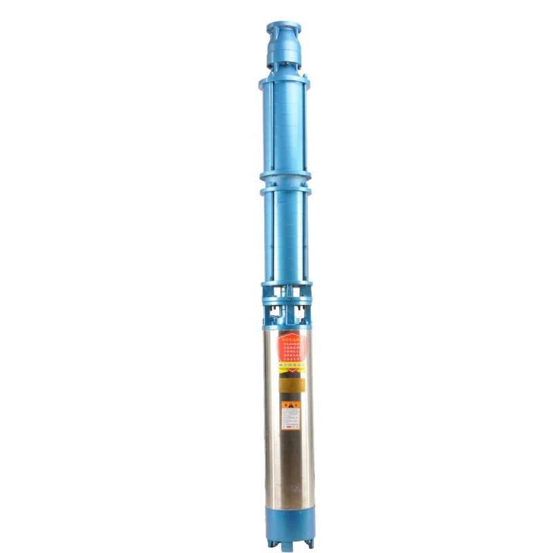
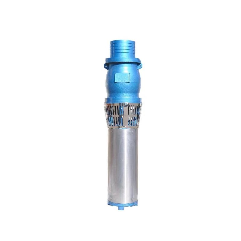
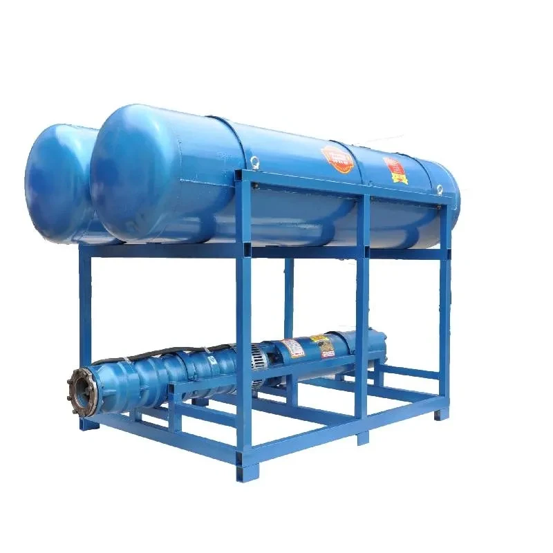
At the heart of the diagram is the submersible pump, which consists of a motor and a pump body. The motor is usually hermetically sealed to prevent water ingress, and its design allows it to be submerged in fluid. The pump impeller moves the water, creating the necessary pressure. Understanding the orientation and positioning of these components in the connection diagram is essential for troubleshooting and maintenance.
Moreover, the connection diagram will highlight the power supply requirements for the pump. Most submersible pumps run on either single-phase or three-phase electricity and require a specific voltage. The diagram typically indicates the connection points for the power supply conductors, ensuring they are connected to the correct terminals on the motor.
Control Panels and Safety Devices
submersible pump connection diagram

Another critical aspect of the connection diagram is the control panel, which manages the operation of the pump. This panel may include switches, sensors, and timers that regulate pumping cycles based on specific parameters, such as water levels. The connection diagram will map out how these components link to the pump and the power supply.
Safety devices are also paramount in a submersible pump system. These devices protect against common issues such as overheating, dry running, and excessive pressure. The connection diagram will often include fuses, circuit breakers, and thermal overload switches, illustrating their placement in relation to the pump and power source.
Wire Management and Grounding
Effective wire management is another essential aspect of submersible pump connection diagrams. Neatly routing wires minimizes the risk of damage and electrical interference. The diagram typically specifies wire types, gauges, and routing methods, ensuring that the installation adheres to electrical codes and best practices.
Grounding is also crucial in any electrical installation, especially in a wet environment. The connection diagram will indicate where to connect grounding wires to ensure electrical safety and compliance with relevant regulations.
Conclusion
In conclusion, understanding a submersible pump connection diagram is vital for anyone involved in the installation or maintenance of these systems. These diagrams not only guide the electrical and hydraulic connections but also promote safety and efficiency. With a clear understanding of each component's role and how they interrelate, technicians can ensure optimal performance and longevity of the submersible pump, making it an invaluable tool in various applications. Proper adherence to these diagrams ultimately leads to successful outcomes in water management and various other hydraulic tasks.
-
Submersible Water Pump: The Efficient 'Power Pioneer' of the Underwater World
NewsJul.01,2025
-
Submersible Pond Pump: The Hidden Guardian of Water Landscape Ecology
NewsJul.01,2025
-
Stainless Well Pump: A Reliable and Durable Pumping Main Force
NewsJul.01,2025
-
Stainless Steel Submersible Pump: An Efficient and Versatile Tool for Underwater Operations
NewsJul.01,2025
-
Deep Well Submersible Pump: An Efficient 'Sucker' of Groundwater Sources
NewsJul.01,2025
-
Deep Water Well Pump: An Efficient 'Sucker' of Groundwater Sources
NewsJul.01,2025
-
 Submersible Water Pump: The Efficient 'Power Pioneer' of the Underwater WorldIn the field of hydraulic equipment, the Submersible Water Pump has become the core equipment for underwater operations and water resource transportation due to its unique design and excellent performance.Detail
 -
 Submersible Pond Pump: The Hidden Guardian of Water Landscape EcologyIn courtyard landscapes, ecological ponds, and even small-scale water conservancy projects, there is a silent yet indispensable equipment - the Submersible Pond Pump.Detail
 -
 Stainless Well Pump: A Reliable and Durable Pumping Main ForceIn the field of water resource transportation, Stainless Well Pump has become the core equipment for various pumping scenarios with its excellent performance and reliable quality.Detail
