Nov . 19, 2024 09:11 Back to list
Submersible Pump Wiring and Connection Guide for Efficient Operation and Maintenance
Understanding Submersible Pump Connection Diagrams
Submersible pumps are an essential component in various applications, including agriculture, construction, and domestic water supply systems. These pumps are designed to operate underwater, making them efficient for moving water or fluid from deep sources. To ensure proper installation and operation, a submersible pump connection diagram is crucial for understanding how to effectively connect the pump within a given system.
What is a Submersible Pump?
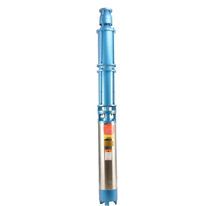
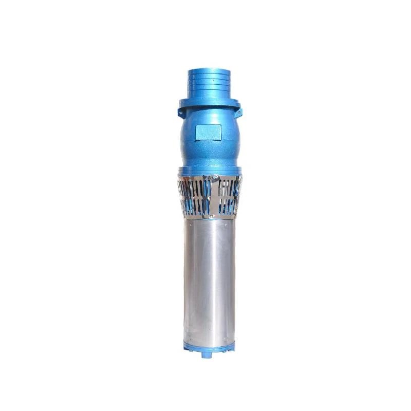
A submersible pump is a device that is fully submerged in the fluid it is pumping. The motor is hermetically sealed, and the pump is designed to push fluid to the surface through a discharge pipe. This design minimizes the risk of cavitation, which can occur when a pump is located above the fluid level. Submersible pumps are widely used for dewatering, irrigation, sewage applications, and groundwater extraction.
Key Components in the Connection Diagram
A submersible pump connection diagram usually includes several key components
1. Pump The main component that moves the fluid. 2. Motor Facilitates the operation of the pump and is often located at the top of the pump housing. 3. Power Supply Typically electric, and required to run the motor. Voltage and amperage specifications need to be considered. 4. Control Panel This may include a pressure switch, timers, or level sensors to automate the pump’s operation. 5. Discharge Pipe This transports the pumped fluid to the desired location. It is crucial that the discharge pipe diameter matches the pump output. 6. Check Valve Installed in the discharge line to prevent backflow when the pump is turned off. 7. Float Switch An optional feature that can automatically turn the pump on or off based on water levels.
Reading the Connection Diagram
submersible pump connection diagram

Understanding a submersible pump connection diagram is vital for ensuring proper installation and maintenance. Here are some important aspects to consider
- Wiring Configuration The diagram typically provides a visual representation of how the motor wires should be connected to the power supply. This often includes specific color coding for wires, which must be adhered to strictly to prevent electrical hazards or pump malfunction. - Connection Points Identify key connection points for power and control. These are often labeled clearly in the diagram, indicating where to connect different components such as the float switch, control panel, and any sensors. - Safety Features Look for any indicated safety components, such as fuses or circuit breakers that should be integrated to protect the pump from potential electrical surges or malfunctions. - Fluid Flow Direction Diagrams usually incorporate arrows showing the direction of fluid flow, which is crucial for correct installation and operational understanding.
Best Practices for Installation
When installing a submersible pump, following the connection diagram closely is crucial. Here are some best practices
- Consult the Manufacturer's Manual Always refer to the specific connection diagram provided by the manufacturer, as designs may vary across different models. - Verify Electrical Connections Ensure that all electrical connections are secure and correctly wired to optimize performance and prevent damage. - Regular Maintenance Checks Periodically inspect the pump system, ensuring that electrical components and plumbing connections are in good condition.
Conclusion
In conclusion, understanding a submersible pump connection diagram is vital for anyone involved in the installation or maintenance of these pumps. Familiarizing oneself with the components, reading the diagram accurately, and adhering to best practices can significantly enhance the efficiency and longevity of submersible pump systems. As these pumps play a vital role in our water management systems, proper knowledge and application are crucial for optimal performance.
-
Submersible Water Pump: The Efficient 'Power Pioneer' of the Underwater World
NewsJul.01,2025
-
Submersible Pond Pump: The Hidden Guardian of Water Landscape Ecology
NewsJul.01,2025
-
Stainless Well Pump: A Reliable and Durable Pumping Main Force
NewsJul.01,2025
-
Stainless Steel Submersible Pump: An Efficient and Versatile Tool for Underwater Operations
NewsJul.01,2025
-
Deep Well Submersible Pump: An Efficient 'Sucker' of Groundwater Sources
NewsJul.01,2025
-
Deep Water Well Pump: An Efficient 'Sucker' of Groundwater Sources
NewsJul.01,2025
-
 Submersible Water Pump: The Efficient 'Power Pioneer' of the Underwater WorldIn the field of hydraulic equipment, the Submersible Water Pump has become the core equipment for underwater operations and water resource transportation due to its unique design and excellent performance.Detail
 -
 Submersible Pond Pump: The Hidden Guardian of Water Landscape EcologyIn courtyard landscapes, ecological ponds, and even small-scale water conservancy projects, there is a silent yet indispensable equipment - the Submersible Pond Pump.Detail
 -
 Stainless Well Pump: A Reliable and Durable Pumping Main ForceIn the field of water resource transportation, Stainless Well Pump has become the core equipment for various pumping scenarios with its excellent performance and reliable quality.Detail
