Nov . 16, 2024 18:36 Back to list
Understanding the Components and Functionality of Submersible Pump Diagrams
Understanding Submersible Pump Diagrams
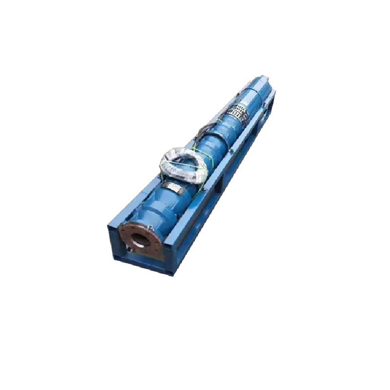
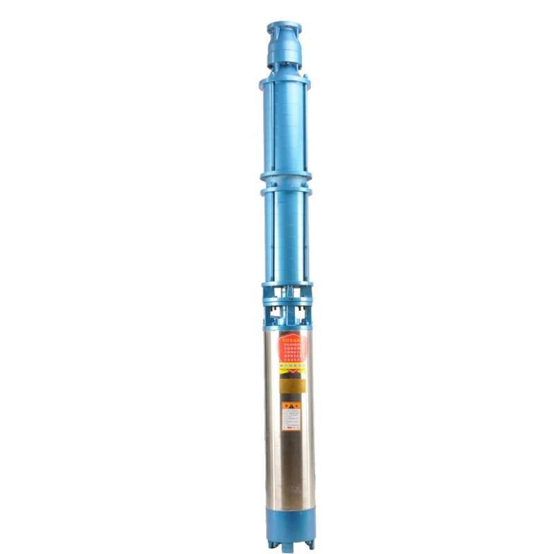
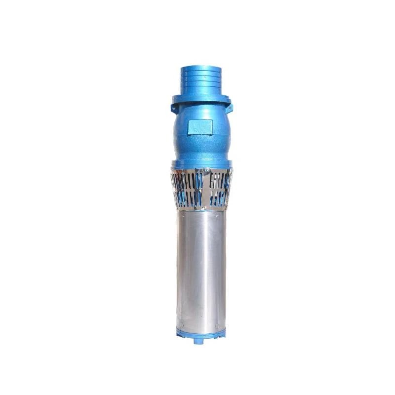
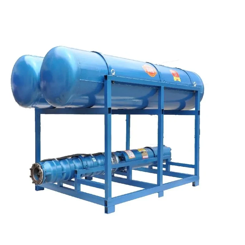
Submersible pumps play a crucial role in various applications, such as dewatering, sewage treatment, and groundwater extraction. These pumps are designed to operate while submerged in liquid, making them efficient for moving water or other fluids from lower to higher elevations. To understand how these pumps work, it's helpful to analyze submersible pump diagrams, which provide insight into their components and operational mechanisms.
A typical submersible pump diagram typically includes parts like the motor, impeller, volute, and discharge head. The motor is often located at the top of the pump and is completely sealed to prevent water from entering. This sealed design allows the motor to be submerged, and it typically consists of an electric motor that drives the impeller, creating suction to draw fluid into the pump.
The impeller is a key component, usually located near the bottom of the pump. It consists of blades that rotate to impart kinetic energy to the fluid, propelling it upward through the volute. The design of the impeller can vary based on the application, with options such as open, semi-open, or closed impellers, each serving specific fluid characteristics and operational requirements.
The volute is the casing that surrounds the impeller. Its role is to convert the high-velocity fluid coming from the impeller into pressure, facilitating the movement of the liquid to the discharge point. The volute is designed to minimize turbulence and ensure smooth flow, which is critical for maintaining efficiency.
submersible pump diagram

At the top of the assembly, the discharge head connects the pump to the tubing or piping system leading the fluid to its final destination. This component usually includes features such as non-return valves and fittings for easy connection to a discharge line. Submersible pumps may also have built-in sensors for monitoring pressure and temperature, which can be depicted in detailed diagrams.
Understanding the flow path depicted in a submersible pump diagram is essential for diagnosing issues and maintaining the unit. Proper installation and operation are vital, as these pumps can be susceptible to wear and tear, especially in abrasive environments or when handling solids.
Maintenance of a submersible pump involves regular checks on the motor and impeller, along with monitoring for any signs of wear, corrosion, or blockages. The diagram can serve as a guide for troubleshooting, allowing technicians to efficiently identify components that may need repair or replacement.
In summary, submersible pump diagrams are invaluable tools for understanding the construction and function of these essential devices. By familiarizing oneself with their components and flow dynamics, operators and maintenance personnel can ensure optimal performance and reliability in various fluid transfer applications. Whether used in municipal systems, agricultural settings, or industrial processes, submersible pumps continuously demonstrate their versatility and efficiency, making them indispensable in many fields.
-
Submersible Water Pump: The Efficient 'Power Pioneer' of the Underwater World
NewsJul.01,2025
-
Submersible Pond Pump: The Hidden Guardian of Water Landscape Ecology
NewsJul.01,2025
-
Stainless Well Pump: A Reliable and Durable Pumping Main Force
NewsJul.01,2025
-
Stainless Steel Submersible Pump: An Efficient and Versatile Tool for Underwater Operations
NewsJul.01,2025
-
Deep Well Submersible Pump: An Efficient 'Sucker' of Groundwater Sources
NewsJul.01,2025
-
Deep Water Well Pump: An Efficient 'Sucker' of Groundwater Sources
NewsJul.01,2025
-
 Submersible Water Pump: The Efficient 'Power Pioneer' of the Underwater WorldIn the field of hydraulic equipment, the Submersible Water Pump has become the core equipment for underwater operations and water resource transportation due to its unique design and excellent performance.Detail
 -
 Submersible Pond Pump: The Hidden Guardian of Water Landscape EcologyIn courtyard landscapes, ecological ponds, and even small-scale water conservancy projects, there is a silent yet indispensable equipment - the Submersible Pond Pump.Detail
 -
 Stainless Well Pump: A Reliable and Durable Pumping Main ForceIn the field of water resource transportation, Stainless Well Pump has become the core equipment for various pumping scenarios with its excellent performance and reliable quality.Detail
