Dec . 07, 2024 02:11 Back to list
submersible pump drawing
Understanding Submersible Pump Drawings A Comprehensive Guide
Submersible pumps are essential devices utilized in various industries for transferring liquids from deep underground sources like wells, boreholes, and reservoirs. Their design and function require precise engineering, which is reflected in detailed technical drawings. These drawings serve as blueprints, illustrating every component and connection necessary for assembling and maintaining these pumps. In this article, we will explore the significance of submersible pump drawings, their components, and how to read and understand them.
The Importance of Submersible Pump Drawings
Submersible pump drawings are critical for several reasons. Firstly, they provide a visual representation of the pump’s design, allowing engineers, technicians, and maintenance personnel to understand complex structures quickly. Secondly, these drawings are essential for quality control, ensuring that each component is fabricated correctly and fits together seamlessly during assembly. Lastly, they serve as a reference for troubleshooting and repairs, offering guidance on where potential issues may arise.
Key Components of a Submersible Pump Drawing
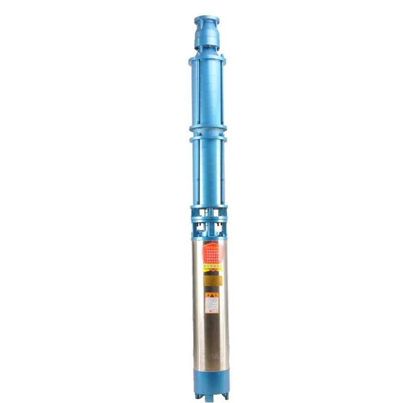
When examining a submersible pump drawing, several critical components may be detailed. Here is a breakdown of the primary sections typically found in these drawings
1. Pump Body The outer casing that houses the pump's internal mechanisms. It is vital for protecting the components and maintaining water-tight integrity.
2. Motor The electric motor generates the power needed to move the water. Drawings often indicate the motor's specifications, including dimensions, power ratings, and mounting points.
3. Impeller This is a rotating component that increases the velocity of the water, converting mechanical energy into hydraulic energy. The drawing specifies the shape and size of the impeller for optimal performance.
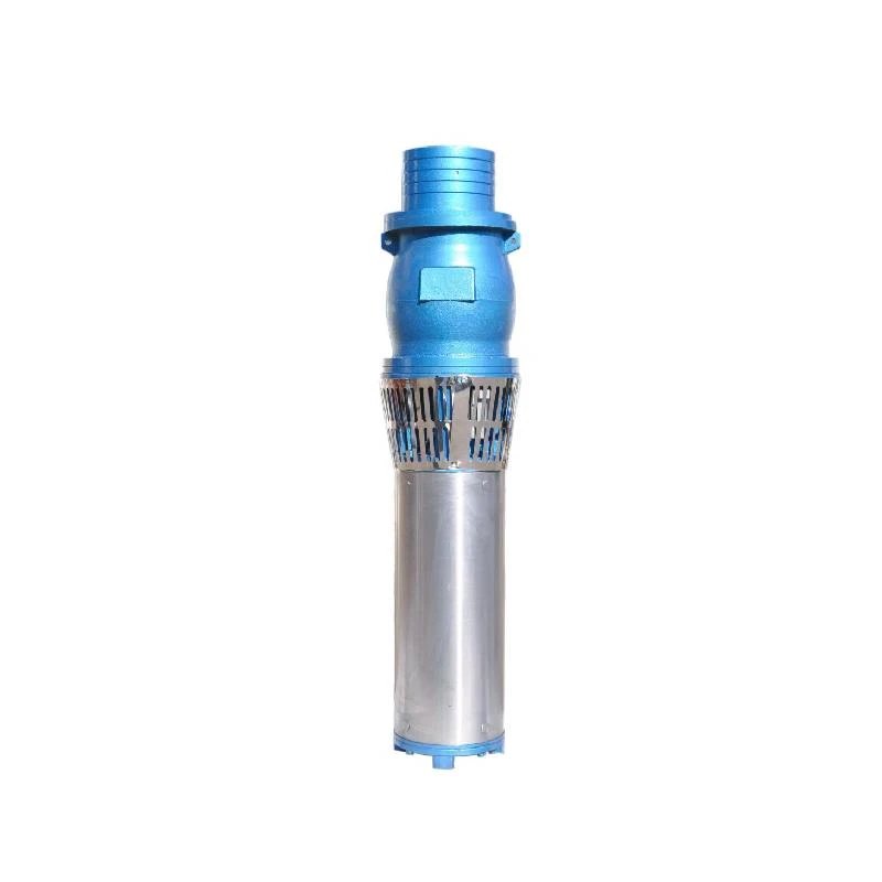
4. Suction Strainer This device prevents debris from entering the pump and clogging internal components. Drawings will illustrate its placement and mesh size.
5. Diffuser After water exits the impeller, the diffuser directs the flow into the discharge pipe. It plays a crucial role in converting velocity into pressure.
submersible pump drawing

6. Discharge Outlet This is where the pressurized water exits the pump. Drawings detail the outlet size, orientation, and type of connection to ensure compatibility with piping systems.
7. Electrical Connections Submersible pumps require proper electrical configurations for safe operation. Drawings contain essential information regarding wiring, protective devices, and grounding points.
Reading and Interpreting Submersible Pump Drawings
Reading submersible pump drawings effectively requires some technical skills and familiarity with symbols and notations used in engineering. Here are some tips to help interpret these drawings
- Symbols and Notations Familiarize yourself with the standard engineering symbols used for components. Often, legends or keys are provided on the drawing to explain these symbols.
- Dimensions and Scale Pay attention to the dimensions provided. Drawings are typically drawn to scale, which means each measurement corresponds accurately to the real-world size of the components.
- Cross-Sections and Views Often, pumps will be illustrated in multiple views, such as top, front, and side elevations, and cross-sectional views. Understanding these different perspectives will help provide a comprehensive view of the assembly.
- Notes and Specifications Look for any notes on the drawing that specify materials, tolerances, or assembly instructions. These annotations provide essential context for the design.
Conclusion
Submersible pump drawings are vital assets in understanding the design, assembly, and maintenance of these devices. By appreciating the complexity and detail found in these blueprints, engineers and technicians can ensure the efficient and safe operation of submersible pumps. Understanding these drawings not only aids in the construction and repair processes but also enhances communication among team members involved in the installation and maintenance of these crucial components of fluid transfer systems. As technology advances, the importance of well-documented engineering drawings will continue to grow, making them an indispensable tool in the design and operation of submersible pumps.
In summary, whether you are an engineer, technician, or operator, grasping the intricate details found within submersible pump drawings is essential for ensuring successful implementation and long-term functionality in various applications.
-
Submersible Water Pump: The Efficient 'Power Pioneer' of the Underwater World
NewsJul.01,2025
-
Submersible Pond Pump: The Hidden Guardian of Water Landscape Ecology
NewsJul.01,2025
-
Stainless Well Pump: A Reliable and Durable Pumping Main Force
NewsJul.01,2025
-
Stainless Steel Submersible Pump: An Efficient and Versatile Tool for Underwater Operations
NewsJul.01,2025
-
Deep Well Submersible Pump: An Efficient 'Sucker' of Groundwater Sources
NewsJul.01,2025
-
Deep Water Well Pump: An Efficient 'Sucker' of Groundwater Sources
NewsJul.01,2025
-
 Submersible Water Pump: The Efficient 'Power Pioneer' of the Underwater WorldIn the field of hydraulic equipment, the Submersible Water Pump has become the core equipment for underwater operations and water resource transportation due to its unique design and excellent performance.Detail
 -
 Submersible Pond Pump: The Hidden Guardian of Water Landscape EcologyIn courtyard landscapes, ecological ponds, and even small-scale water conservancy projects, there is a silent yet indispensable equipment - the Submersible Pond Pump.Detail
 -
 Stainless Well Pump: A Reliable and Durable Pumping Main ForceIn the field of water resource transportation, Stainless Well Pump has become the core equipment for various pumping scenarios with its excellent performance and reliable quality.Detail
