Dec . 07, 2024 05:16 Back to list
submersible pump drawing
Understanding Submersible Pump Drawings A Comprehensive Guide
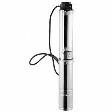
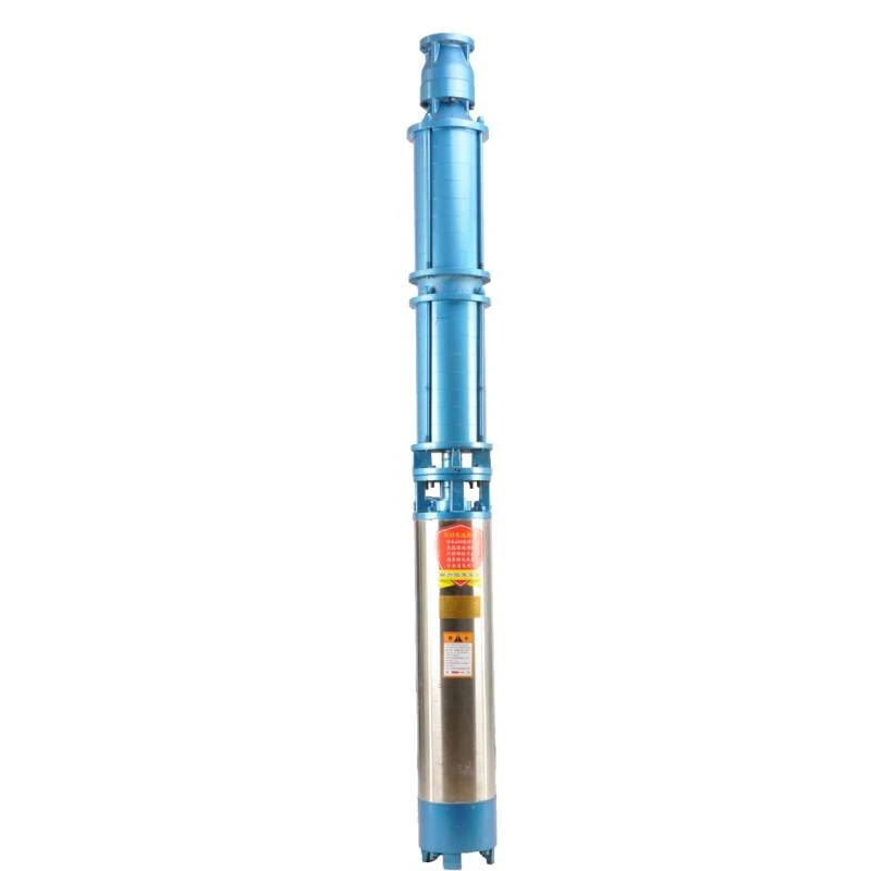
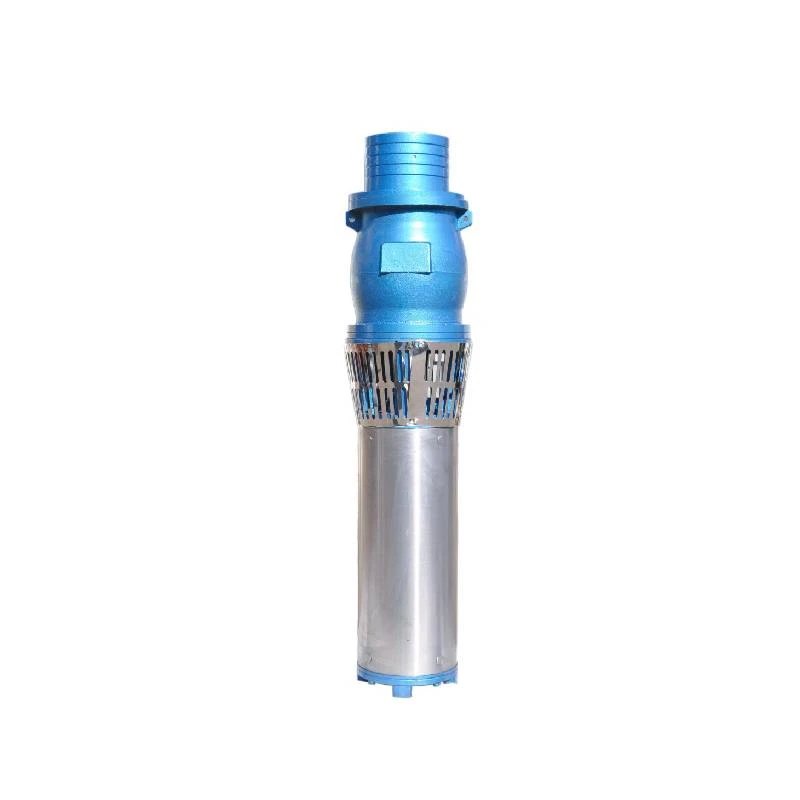
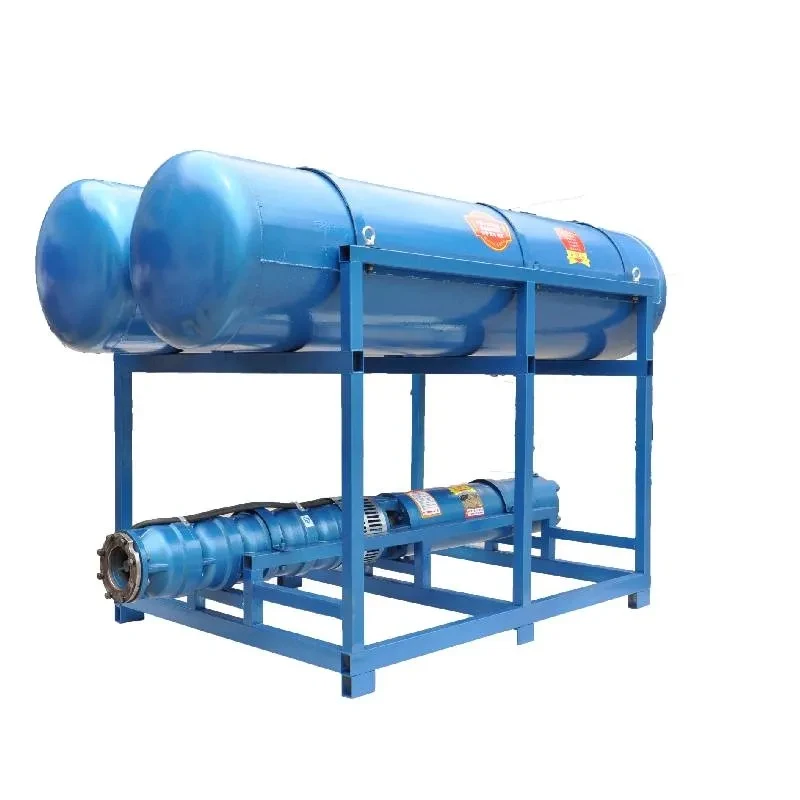
Submersible pumps are essential components in various applications, from residential water supply to industrial dewatering processes. These pumps are designed to operate while fully submerged in the fluid they are pumping, making them highly efficient and ideal for deep wells, sewage systems, and various other settings. Understanding submersible pump drawings is crucial for engineers, technicians, and anyone involved in the installation or maintenance of these devices. This article aims to demystify the intricacies of submersible pump drawings and highlight their significance in the design and operational phases.
What is a Submersible Pump Drawing?
A submersible pump drawing is a schematic representation that details the various components and systems within a submersible pump. These drawings utilize specific symbols and nomenclature to convey information about the pump's design, configuration, and operational parameters. They serve as essential tools for communicating complex information clearly and concisely among engineers, fabricators, and end-users.
Key Components Illustrated in the Drawings
Submersible pump drawings typically include several key components, each critical for the pump's performance
1. Pump Body The main structure containing the motor and impeller. Drawings will often highlight materials used and dimensions.
2. Motor Usually located at the top or center of the pump, the motor drives the impeller. Its specifications, such as power rating and efficiency, are crucial to understanding the pump's capabilities.
3. Impeller The rotating part that creates the flow of fluid. Drawings often depict the type of impeller, which can vary in design depending on the application (e.g., centrifugal or positive displacement).
4. Seals and Bearings These components prevent leakage and ensure smooth operation. The drawings may include details about the materials used, particularly for seals, which are critical in submersible environments.
submersible pump drawing

5. Discharge Port This is where the fluid exits the pump and is an essential aspect of the flow dynamics illustrated in the drawings.
6. Cable Entry Points The points where electrical cables enter the pump. Drawings often include details about cable types and lengths, critical for ensuring proper electrical connections.
Importance of Accurate Drawings
Accurate submersible pump drawings are vital for several reasons
- Installation Detailed drawings provide essential information for proper installation, ensuring that all components fit together correctly and adhere to specified tolerances.
- Maintenance For maintenance teams, these drawings serve as a reference when troubleshooting and repairing pump failures. They help identify potential issues and guide the technician through service procedures.
- Compliance and Standards Many industries are subject to regulations regarding equipment design and safety. Comprehensive drawings help ensure that submersible pumps meet these standards, reducing liability and enhancing safety.
- Training Clear, well-annotated drawings are useful educational tools for training new personnel, facilitating a better understanding of how components interact within the system.
Conclusion
Understanding submersible pump drawings is integral to the design, installation, and maintenance of these vital machines. By outlining component specifications, operational parameters, and compliance considerations, these drawings serve as indispensable resources in ensuring optimal performance and longevity of submersible pumps. Whether you are an engineer, technician, or simply interested in pump technology, familiarizing yourself with this essential documentation will empower you to navigate the complexities of submersible pump systems more effectively. As technology advances, the inclusion of digital tools and software will further enhance the precision and usability of these vital drawings, making it easier than ever to harness the power of submersible pumps in various applications.
-
Submersible Water Pump: The Efficient 'Power Pioneer' of the Underwater World
NewsJul.01,2025
-
Submersible Pond Pump: The Hidden Guardian of Water Landscape Ecology
NewsJul.01,2025
-
Stainless Well Pump: A Reliable and Durable Pumping Main Force
NewsJul.01,2025
-
Stainless Steel Submersible Pump: An Efficient and Versatile Tool for Underwater Operations
NewsJul.01,2025
-
Deep Well Submersible Pump: An Efficient 'Sucker' of Groundwater Sources
NewsJul.01,2025
-
Deep Water Well Pump: An Efficient 'Sucker' of Groundwater Sources
NewsJul.01,2025
-
 Submersible Water Pump: The Efficient 'Power Pioneer' of the Underwater WorldIn the field of hydraulic equipment, the Submersible Water Pump has become the core equipment for underwater operations and water resource transportation due to its unique design and excellent performance.Detail
 -
 Submersible Pond Pump: The Hidden Guardian of Water Landscape EcologyIn courtyard landscapes, ecological ponds, and even small-scale water conservancy projects, there is a silent yet indispensable equipment - the Submersible Pond Pump.Detail
 -
 Stainless Well Pump: A Reliable and Durable Pumping Main ForceIn the field of water resource transportation, Stainless Well Pump has become the core equipment for various pumping scenarios with its excellent performance and reliable quality.Detail
