Nov . 12, 2024 17:20 Back to list
submersible pump installation diagram
Understanding Submersible Pump Installation Diagram
Submersible pumps are essential for various applications, particularly in water extraction, drainage, and sewage management. Understanding how to install these pumps properly is crucial for achieving optimal performance and longevity. An installation diagram serves as a visual guide, illustrating the necessary components and steps involved in the installation process.
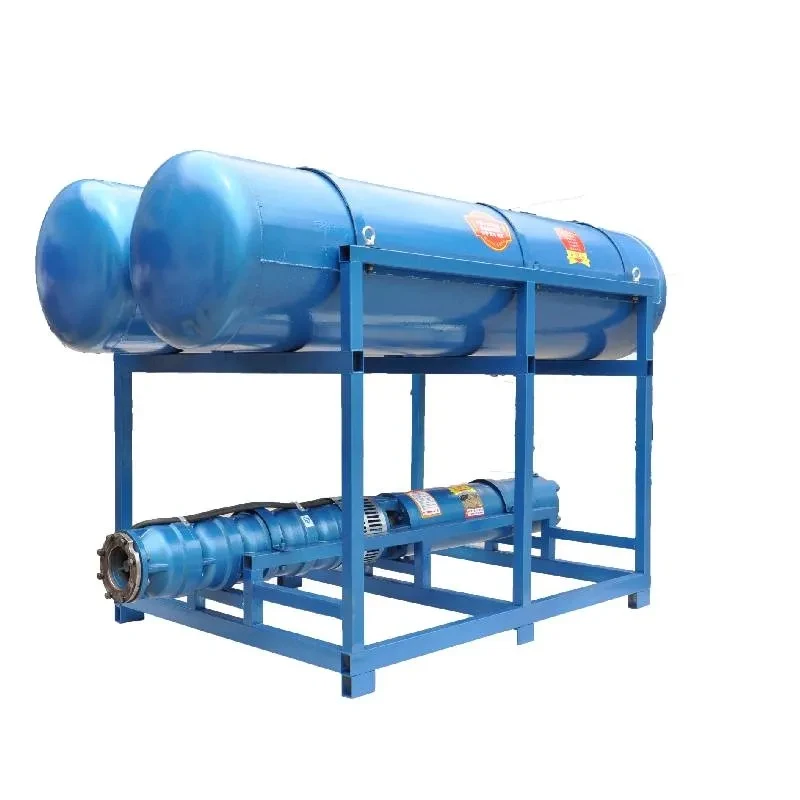
A typical submersible pump installation diagram showcases several key elements. Firstly, it illustrates the placement of the pump. Positioned below the water level, the pump is designed to push water to the surface rather than pull it, which is a fundamental characteristic differentiating it from other types of pumps. The diagram usually denotes the depth at which the pump should be submerged, ensuring that it operates efficiently while minimizing risk factors such as cavitation.
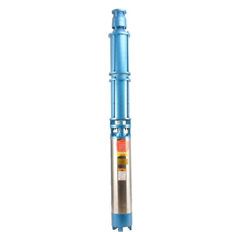
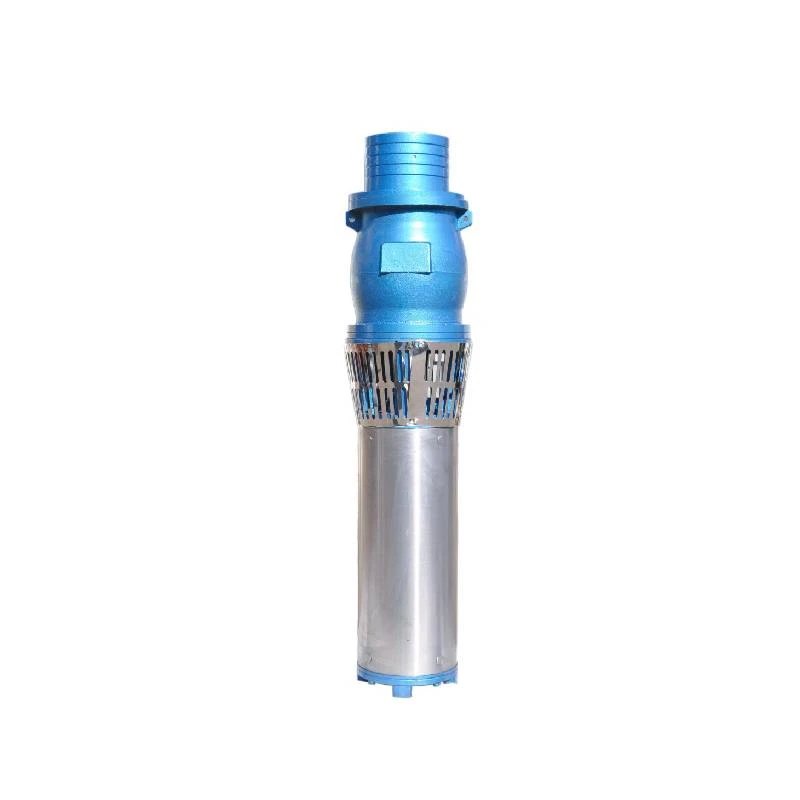
The pump itself consists of several components, including an electric motor, impellers, and a discharge head. The installation diagram provides a clear layout of these parts and their orientations. For instance, it shows how the impellers are arranged within the pump casing, crucial for maintaining the hydraulic balance and improving the overall efficiency of water movement.
Next, the installation diagram will also highlight the piping system connected to the pump. Proper sizing and the right type of pipes are vital for reducing friction losses and preventing damage to the piping due to high flow rates. The diagram usually specifies the diameter and material of the discharge pipes, which typically connect the pump to the system that transports water to its final destination. It is essential to ensure that these materials are compatible with the fluid being pumped, to avoid corrosion and degradation over time.
submersible pump installation diagram

Other important components depicted in the installation diagram include the electrical system responsible for powering the pump. This section usually features wiring details, such as grounding requirements and the electrical disconnect switches, which enhance safety during operation and maintenance. Understanding this part is crucial, as improper electrical connections can lead to significant hazards, including short circuits and equipment failure.
Additionally, a submersible pump installation diagram may illustrate monitoring equipment, like pressure gauges or flow meters, which provide valuable data about the pump's performance. Utilizing these tools helps assess the pump's operational status and allows for timely maintenance, minimizing downtime and repair costs.
Moreover, the diagram often includes a section on safety precautions. This may indicate the need for a check valve to prevent backflow or highlight the importance of regular inspections to avoid blockages caused by debris. Adhering to these guidelines is vital for maintaining the efficiency and safety of the installation.
In summary, a submersible pump installation diagram is a comprehensive tool that encompasses the essential components of the system, guiding users through the installation process. By understanding the layout and function of each part, one can ensure a successful installation, leading to efficient and reliable operation. Proper installation not only enhances the performance of submersible pumps but also prolongs their lifespan, making them a valuable addition to any water management system.
-
Submersible Water Pump: The Efficient 'Power Pioneer' of the Underwater World
NewsJul.01,2025
-
Submersible Pond Pump: The Hidden Guardian of Water Landscape Ecology
NewsJul.01,2025
-
Stainless Well Pump: A Reliable and Durable Pumping Main Force
NewsJul.01,2025
-
Stainless Steel Submersible Pump: An Efficient and Versatile Tool for Underwater Operations
NewsJul.01,2025
-
Deep Well Submersible Pump: An Efficient 'Sucker' of Groundwater Sources
NewsJul.01,2025
-
Deep Water Well Pump: An Efficient 'Sucker' of Groundwater Sources
NewsJul.01,2025
-
 Submersible Water Pump: The Efficient 'Power Pioneer' of the Underwater WorldIn the field of hydraulic equipment, the Submersible Water Pump has become the core equipment for underwater operations and water resource transportation due to its unique design and excellent performance.Detail
 -
 Submersible Pond Pump: The Hidden Guardian of Water Landscape EcologyIn courtyard landscapes, ecological ponds, and even small-scale water conservancy projects, there is a silent yet indispensable equipment - the Submersible Pond Pump.Detail
 -
 Stainless Well Pump: A Reliable and Durable Pumping Main ForceIn the field of water resource transportation, Stainless Well Pump has become the core equipment for various pumping scenarios with its excellent performance and reliable quality.Detail
