Nov . 03, 2024 00:17 Back to list
well submersible pump diagram
Understanding Well Submersible Pump Diagrams
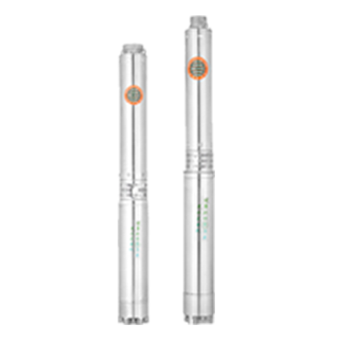
Well submersible pumps are essential components in both residential and agricultural settings, providing an efficient means of drawing water from underground sources. To fully appreciate how these pumps function, it is vital to understand the well submersible pump diagram, which illustrates the key elements and operations of the system.
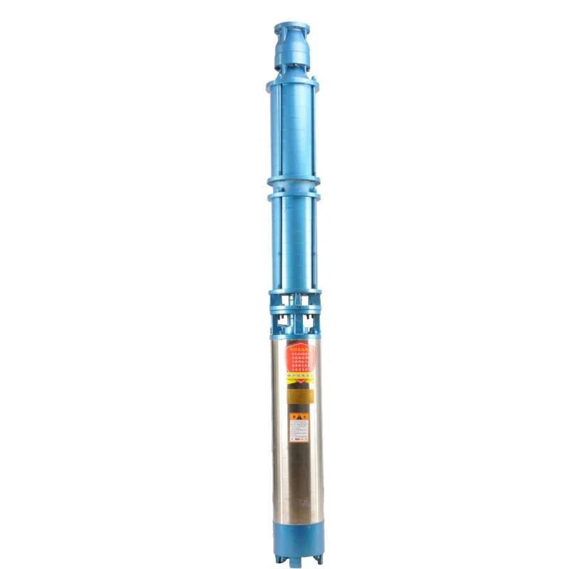
A typical well submersible pump diagram comprises various sections, each representing a crucial part of the pump. At the top of the diagram, you often see the electrical supply connection, which powers the motor. The motor is a critical component, as it drives the pump impellers, pushing water to the surface. Most submersible pumps utilize a three-phase or single-phase electric motor, depending on their application and design.
Moving down, the diagram illustrates the pump assembly, which includes multiple impellers arranged in a series. These impellers are responsible for creating the necessary pressure to lift the water. As the motor spins, it rotates the impellers, which in turn forces the water upwards through the pump casing. The diagram will typically show the water intake section at the bottom, where water enters the pump from the well.
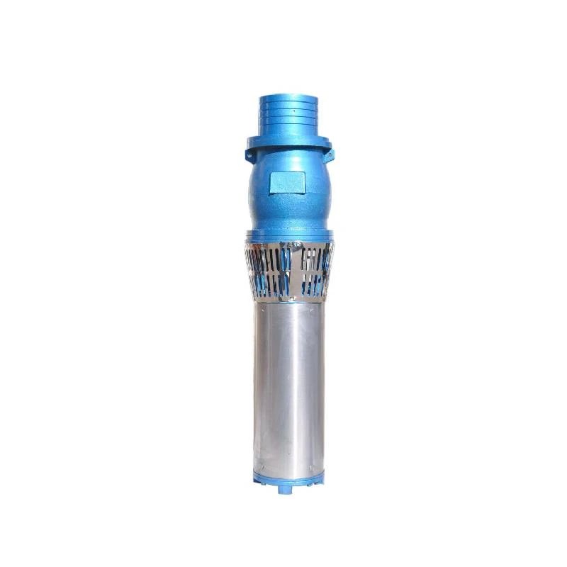
The pump casing, usually depicted as a cylindrical shape, encases the impellers and directs the flow of water. It features a check valve at the discharge point; this valve is vital as it prevents backflow, ensuring that the water remains flowing upwards when the pump is turned off. The discharge line is depicted extending from the top of the pump, showing how the water is delivered to the surface and into the home or distribution system.
well submersible pump diagram

Additionally, many diagrams include a schematic of the control panel, which houses various switches and controls for operation. This panel aids in monitoring the pump's performance and provides a means to shut it off in case of emergencies or maintenance needs. Safety devices, such as pressure switches and overload protection, are also typically shown, emphasizing their role in preventing pump damage and ensuring efficient operation.
Furthermore, the well submersible pump diagram often highlights various installation components, including the well casing and protective screen. The well casing secures the well structure and prevents contamination while allowing the pump to operate within the aquifer boundary. The screen at the water intake helps filter out sand and debris, ensuring that only clean water enters the pump.
Understanding a well submersible pump diagram provides valuable insights into the operation and maintenance of the system. Recognizing each component and its function helps users troubleshoot potential issues and perform routine maintenance effectively. This knowledge is critical for ensuring long-term performance and reliability of the well water system.
In conclusion, a well submersible pump diagram serves as a comprehensive guide that illustrates the function and integration of various components within the pump system. By familiarizing oneself with this diagram, individuals can enhance their understanding of submersible pump mechanics, leading to improved maintenance practices and ultimately, a better water supply solution. Whether for residential use or agricultural needs, having a grasp of these diagrams is indispensable in the world of well water management.
-
Submersible Water Pump: The Efficient 'Power Pioneer' of the Underwater World
NewsJul.01,2025
-
Submersible Pond Pump: The Hidden Guardian of Water Landscape Ecology
NewsJul.01,2025
-
Stainless Well Pump: A Reliable and Durable Pumping Main Force
NewsJul.01,2025
-
Stainless Steel Submersible Pump: An Efficient and Versatile Tool for Underwater Operations
NewsJul.01,2025
-
Deep Well Submersible Pump: An Efficient 'Sucker' of Groundwater Sources
NewsJul.01,2025
-
Deep Water Well Pump: An Efficient 'Sucker' of Groundwater Sources
NewsJul.01,2025
-
 Submersible Water Pump: The Efficient 'Power Pioneer' of the Underwater WorldIn the field of hydraulic equipment, the Submersible Water Pump has become the core equipment for underwater operations and water resource transportation due to its unique design and excellent performance.Detail
 -
 Submersible Pond Pump: The Hidden Guardian of Water Landscape EcologyIn courtyard landscapes, ecological ponds, and even small-scale water conservancy projects, there is a silent yet indispensable equipment - the Submersible Pond Pump.Detail
 -
 Stainless Well Pump: A Reliable and Durable Pumping Main ForceIn the field of water resource transportation, Stainless Well Pump has become the core equipment for various pumping scenarios with its excellent performance and reliable quality.Detail
