Dec . 12, 2024 10:31 Back to list
well submersible pump diagram
Understanding the Well Submersible Pump Diagram A Comprehensive Guide
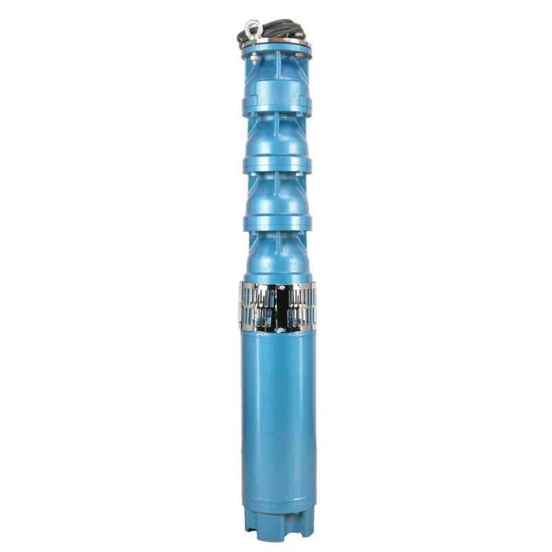
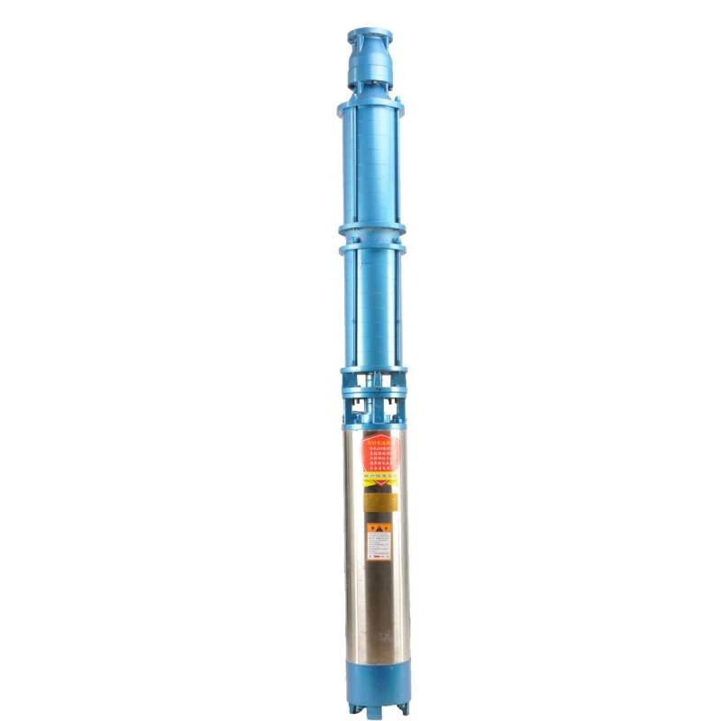
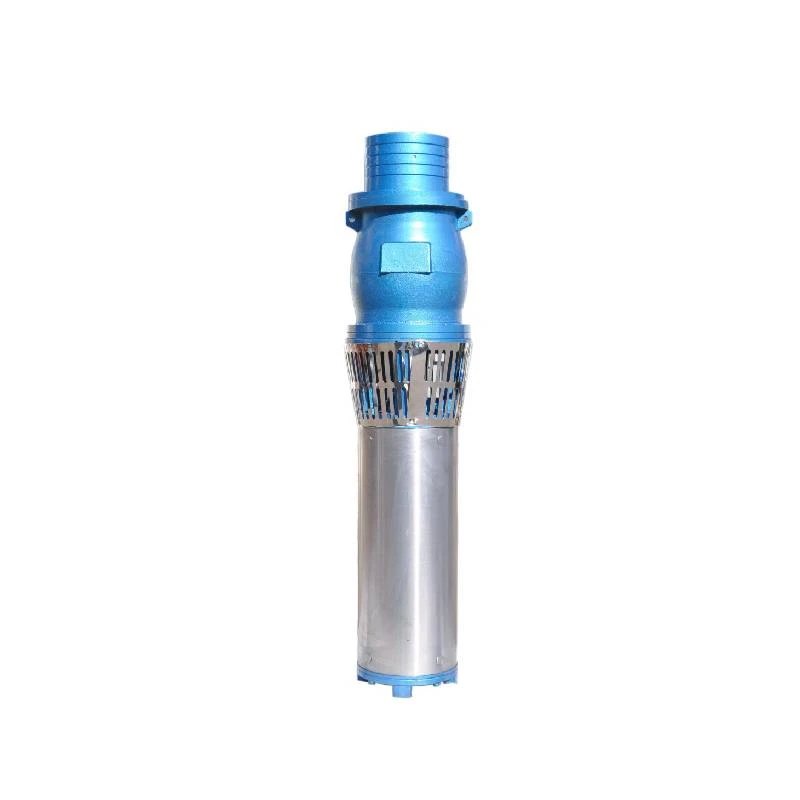
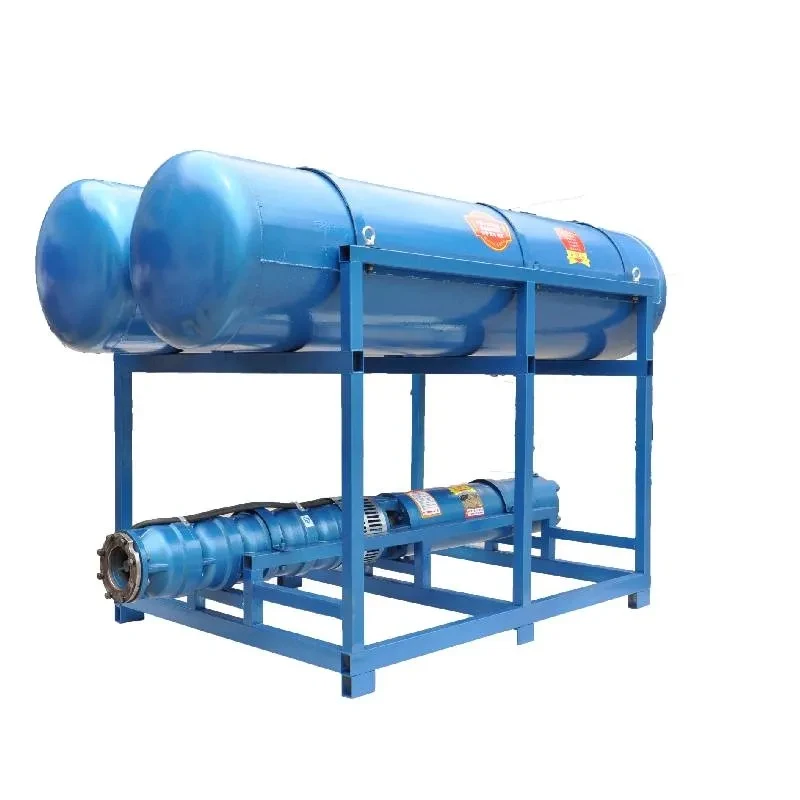
In examining the functioning of water wells, one of the most critical components is the well submersible pump. This pump is designed to lift water from underground sources and deliver it to the surface efficiently. The well submersible pump diagram provides a visual representation of how these systems operate, showcasing various parts and their functions. In this article, we will delve into the anatomy of a well submersible pump and its operating principles based on the typical diagram.
Components of a Well Submersible Pump
A well submersible pump consists of several key components, each of which plays an essential role in its operation. The primary components include
1. Motor Located at the bottom of the pump, the motor is responsible for generating the energy needed to lift the water. Many submersible pumps use an electric motor that is designed to operate underwater without the risk of short-circuiting.
2. Pump Bowl This component houses the impeller, which is crucial for moving the water. The impeller spins at a high rate, creating a centrifugal force that pushes the water upwards through the pump.
3. Stage A multi-stage submersible pump includes multiple impellers and diffusers arranged in a series. Each stage increases the water pressure, allowing the pump to lift water from greater depths.
4. Discharge Head This component is situated at the top of the pump and serves to direct the water out from the pump and into the discharge pipe. The discharge head also provides structural support for the pump system.
6. Cable and Wire The power supply to the motor comes through cables, which must be water-resistant to ensure reliability over time.
well submersible pump diagram

How a Well Submersible Pump Works
Understanding the operation of a well submersible pump begins with the realization that its design allows it to function underwater effectively. When the motor turns on, the impeller starts rotating, creating a low-pressure area that draws water in through the suction strainer. The water then moves into the pump bowl, where it experiences the centrifugal force from the spinning impeller.
As water passes through each stage (impeller and diffuser), its velocity increases, subsequently transforming into higher pressure. Ultimately, the pressurized water exits the pump through the discharge head and travels through pipes to reach its destination, whether a home, irrigation system, or storage tank.
Advantages of Submersible Pumps
One of the key benefits of submersible pumps is their ability to function efficiently at significant depths. Since they are submerged in the water, they do not require priming, making them a convenient choice for many applications. Additionally, submersible pumps tend to have higher energy efficiency compared to surface pumps, as they eliminate the need to push water to the surface.
Moreover, well submersible pumps operate quietly due to their underwater location, making them a preferred option in residential areas. They also reduce the risk of cavitation and air lock, issues common in other types of pumps.
Conclusion
The well submersible pump diagram serves as an invaluable tool for understanding this essential water system. Each component meticulously designed contributes to the pump's overall efficiency and functionality. By familiarizing ourselves with how these systems work, we can appreciate the vital role they play in providing clean and reliable water access for agriculture, industry, and residential needs.
Whether for a private well or a municipal water system, knowing how to read and understand the well submersible pump diagram empowers users to maintain and troubleshoot their systems effectively, ensuring longevity and reliable performance in extracting precious groundwater resources.
-
Submersible Water Pump: The Efficient 'Power Pioneer' of the Underwater World
NewsJul.01,2025
-
Submersible Pond Pump: The Hidden Guardian of Water Landscape Ecology
NewsJul.01,2025
-
Stainless Well Pump: A Reliable and Durable Pumping Main Force
NewsJul.01,2025
-
Stainless Steel Submersible Pump: An Efficient and Versatile Tool for Underwater Operations
NewsJul.01,2025
-
Deep Well Submersible Pump: An Efficient 'Sucker' of Groundwater Sources
NewsJul.01,2025
-
Deep Water Well Pump: An Efficient 'Sucker' of Groundwater Sources
NewsJul.01,2025
-
 Submersible Water Pump: The Efficient 'Power Pioneer' of the Underwater WorldIn the field of hydraulic equipment, the Submersible Water Pump has become the core equipment for underwater operations and water resource transportation due to its unique design and excellent performance.Detail
 -
 Submersible Pond Pump: The Hidden Guardian of Water Landscape EcologyIn courtyard landscapes, ecological ponds, and even small-scale water conservancy projects, there is a silent yet indispensable equipment - the Submersible Pond Pump.Detail
 -
 Stainless Well Pump: A Reliable and Durable Pumping Main ForceIn the field of water resource transportation, Stainless Well Pump has become the core equipment for various pumping scenarios with its excellent performance and reliable quality.Detail
