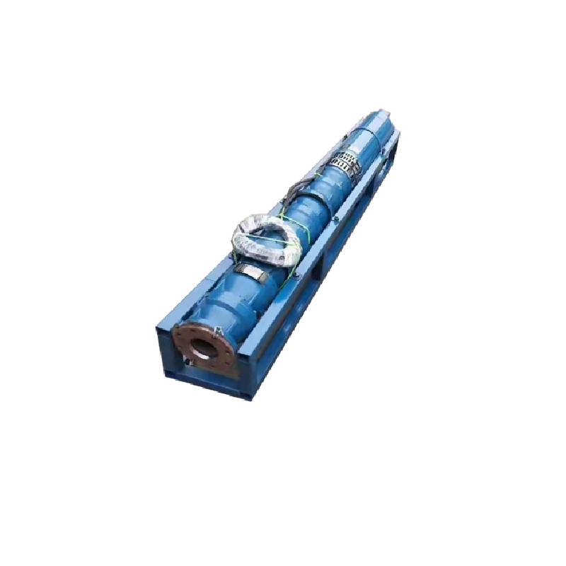
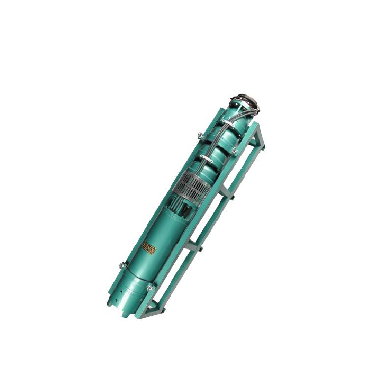
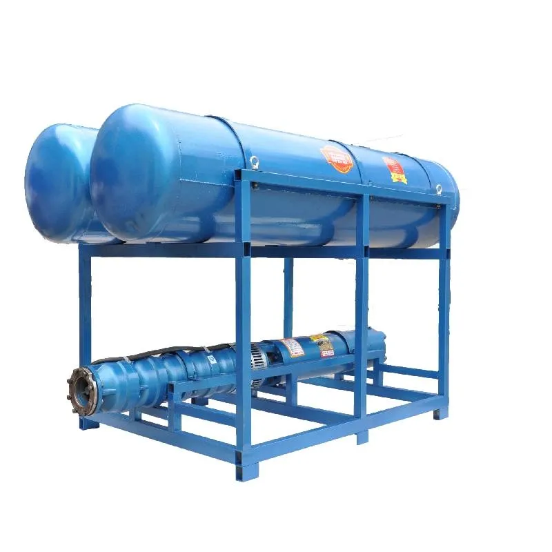
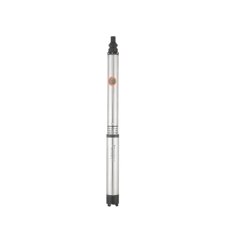
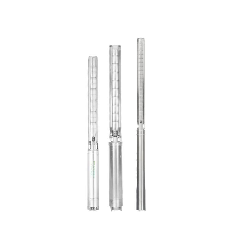
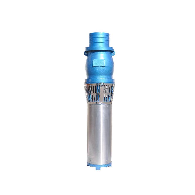
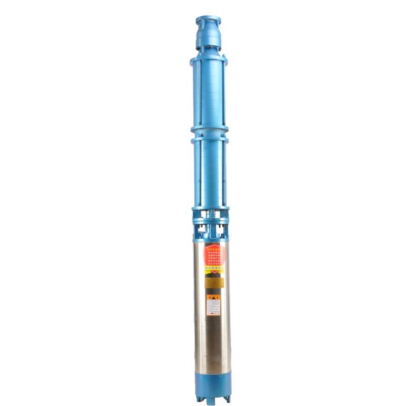
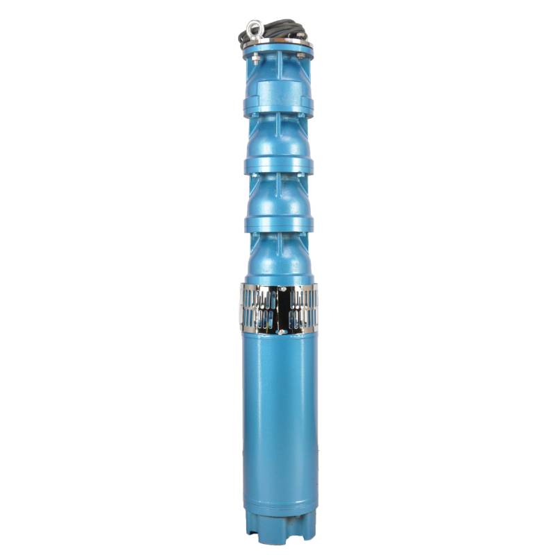
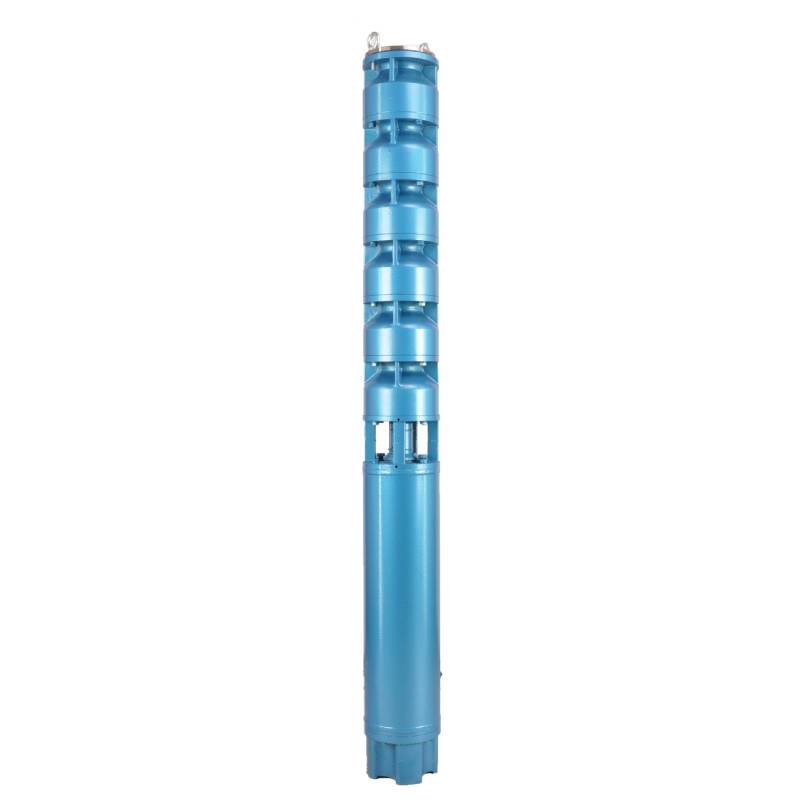
This series of fountain pump is a special fountain pump developed by our factory. The pump motor core is made of high quality cold rolled silicon steel, which makes the pump more efficient, has good magnetic conductivity, and does not produce heat when starting frequently. The two ends of the motor rotor are equipped with alloy copper sleeves with water as lubricant. Stainless steel bushings replace ball bearings, avoiding the problems of easy rust of ball bearings and burnout of motor due to lack of oil and wear. Most suitable for music fountain, all models can be used horizontally.
1, крыніца харчавання: трохфазны пераменны ток 380 В (допуск + / - 5%), 50 Гц (допуск + / - 1%).
2, якасць вады:
(1) water temperature is not higher than 20 °C;
(2) утрыманне цвёрдых прымешак (масавыя суадносіны) не перавышае 0,01%;
(3) Значэнне PH (pH) 6,5-8,5;
(4) утрыманне серавадароду не перавышае 1,5 мг/л;
(5) ўтрыманне іёнаў хларыду не перавышае 400 мг/л.
3, рухавік зачынены або напоўнены вадой у мокрай канструкцыі, перад выкарыстаннем паражніну погружного рухавіка павінна быць поўная чыстай вады, каб прадухіліць памылковае запаўненне, а затым зацягніце ўпырск вады, балты выпуску паветра, у адваротным выпадку нельга выкарыстоўваць
4, погружной помпа павінен быць цалкам пагружаны ў ваду, глыбіня апускання не больш за 70 м, ніжняя частка погружной помпы ад дна свідравіны не менш за 3 м.
5, паток вады ў свідравіне павінен быць у стане задаволіць выхад вады погружной помпы і бесперапыннай працы, выхад вады з погружной помпы павінен кантралявацца ў 0,7 - 1,2 разы перавышае намінальны паток.
6, калодзеж павінен быць прамым, погружной помпа не можа быць выкарыстаны або скінуты, толькі вертыкальнае выкарыстанне.
7, погружной помпа павінен быць узгоднены з кабелем у адпаведнасці з патрабаваннямі, і знешняя прылада абароны ад перагрузкі.
8, помпа строга забаронена без вады халастога ходу выпрабавальнай машыны
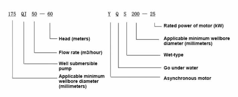
| мадэль | Расход (м3/г) | Галава (м) |
Хуткасць кручэння (змена/кропка) |
Вадзяной помпа (%) | Разетка дыяметр (мм) |
Добра ўжываецца дыяметр (мм) |
Ацэнены power(KW) |
Ацэнены напружанне (В) |
Ацэнены ток (А) |
Маторная эфектыўнасць (%) | power factorcosφ | адзінка Максімальны радыяльны памер (мм) |
Заўвага | |||||||||
| 250QJ50-40 | 50 | 40 | 2875 | 72 | 80 | 250вышэй | 9.2 | 380 | 21.7 | 78.5 | 0.82 | 233 | ||||||||||
| 250QJ50-60 | 60 | 13 | 30.1 | 80.0 | 0.82 | |||||||||||||||||
| 250QJ50-80 | 80 | 18.5 | 40.8 | 82.0 | 0.84 | |||||||||||||||||
| 250QJ50-100 | 100 | 22 | 47.9 | 83.0 | 0.84 | |||||||||||||||||
| 250QJ50-120 | 120 | 25 | 53.8 | 84.0 | 0.84 | |||||||||||||||||
| 250QJ50-140 | 140 | 30 | 64.2 | 84.5 | 0.84 | |||||||||||||||||
| 250QJ50-160 | 160 | 37 | 77.8 | 85.0 | 0.85 | |||||||||||||||||
| 250QJ50-200 | 200 | 45 | 94.1 | 85.5 | 0.85 | |||||||||||||||||
| 250QJ50-240 | 240 | 55 | 114.3 | 86.0 | 0.85 | |||||||||||||||||
| 250QJ50-280 | 280 | 63 | 131.0 | 86.0 | 0.85 | |||||||||||||||||
| 250QJ50-320 | 320 | 75 | 152.3 | 87.0 | 0.86 | |||||||||||||||||
| 250QJ50-400 | 400 | 90 | 182.8 | 87.0 | 0.86 | |||||||||||||||||
| 250QJ50-440 | 440 | 100 | 203.1 | 87.0 | 0.86 | |||||||||||||||||
| 250QJ63-40 | 63 | 40 | 2875 | 74 | 80 | 250вышэй | 11 | 380 | 25.8 | 79.0 | 0.82 | 233 | ||||||||||
| 250QJ63-60 | 60 | 18.5 | 40.8 | 82.0 | 0.84 | |||||||||||||||||
| 250QJ63-80 | 80 | 22 | 47.9 | 83.0 | 0.84 | |||||||||||||||||
| 250QJ63-100 | 100 | 30 | 64.2 | 84.5 | 0.84 | |||||||||||||||||
| 250QJ63-120 | 120 | 37 | 77.8 | 85.0 | 0.85 | |||||||||||||||||
| 250QJ63-160 | 160 | 45 | 94.1 | 85.5 | 0.85 | |||||||||||||||||
| 250QJ63-200 | 200 | 55 | 114.3 | 86.0 | 0.85 | |||||||||||||||||
| 250QJ63-220 | 220 | 63 | 131.0 | 86.0 | 0.85 | |||||||||||||||||
| 250QJ63-260 | 260 | 75 | 152.3 | 87.0 | 0.86 | |||||||||||||||||
| 250QJ63-300 | 300 | 90 | 182.8 | 87.0 | 0.86 | |||||||||||||||||
| 250QJ63-360 | 360 | 100 | 203.1 | 87.0 | 0.86 | |||||||||||||||||
| 250QJ80-20 | 80 | 20 | 2875 | 75 | 100 | 250вышэй | 7.5 | 380 | 18.0 | 78.0 | 0.81 | 233 | ||||||||||
| 250QJ80-40 | 40 | 15 | 33.9 | 81.0 | 0.83 | |||||||||||||||||
| 250QJ80-60 | 60 | 22 | 47.9 | 83.0 | 0.84 | |||||||||||||||||
| 250QJ80-80 | 80 | 30 | 64.2 | 84.5 | 0.84 | |||||||||||||||||
| 250QJ80-100 | 100 | 37 | 77.8 | 85.0 | 0.85 | |||||||||||||||||
| 250QJ80-120 | 120 | 45 | 94.1 | 85.5 | 0.85 | |||||||||||||||||
| 250QJ80-160 | 80 | 160 | 2875 | 75 | 100 | 250вышэй | 55 | 380 | 114.3 | 86.0 | 0.85 | 233 | ||||||||||
| 250QJ80-180 | 180 | 63 | 131.0 | 86.0 | 0.85 | |||||||||||||||||
| 250QJ80-200 | 200 | 75 | 152.3 | 87.0 | 0.86 | |||||||||||||||||
| 250QJ80-240 | 240 | 90 | 182.8 | 87.0 | 0.86 | |||||||||||||||||
| 250QJ80-280 | 280 | 100 | 203.1 | 87.0 | 0.86 | |||||||||||||||||
| 250QJ100-18 | 100 | 18 | 2875 | 75 | 100 | 250вышэй | 7.5 | 380 | 18.0 | 78.0 | 0.81 | 233 | ||||||||||
| 250QJ100-36 | 36 | 15 | 33.9 | 81.0 | 0.83 | |||||||||||||||||
| 250QJ100-54 | 54 | 25 | 53.8 | 84.0 | 0.84 | |||||||||||||||||
| 250QJ100-72 | 72 | 30 | 64.2 | 84.5 | 0.84 | |||||||||||||||||
| 250QJ100-90 | 90 | 37 | 77.8 | 85.0 | 0.85 | |||||||||||||||||
| 250QJ100-108 | 108 | 45 | 94.1 | 85.5 | 0.85 | |||||||||||||||||
| 250QJ100-126 | 126 | 55 | 114.3 | 86.0 | 0.85 | |||||||||||||||||
| 250QJ100-144 | 144 | 63 | 131.0 | 86.0 | 0.85 | |||||||||||||||||
| 250QJ100-162 | 162 | 75 | 152.3 | 87.0 | 0.86 | |||||||||||||||||
| 250QJ100-198 | 198 | 90 | 182.8 | 87.0 | 0.86 | |||||||||||||||||
| 250QJ100-216 | 216 | 100 | 203.1 | 87.0 | 0.86 | |||||||||||||||||
| 250QJ125-16 | 125 | 16 | 2875 | 76 | 125 | 250вышэй | 9.2 | 380 | 21.7 | 78.5 | 0.82 | 233 | ||||||||||
| 250QJ125-32 | 32 | 18.5 | 40.8 | 82.0 | 0.84 | |||||||||||||||||
| 250QJ125-48 | 48 | 25 | 53.8 | 84.0 | 0.84 | |||||||||||||||||
| 250QJ125-64 | 64 | 37 | 77.8 | 85.0 | 0.85 | |||||||||||||||||
| 250QJ125-80 | 80 | 45 | 94.1 | 85.5 | 0.85 | |||||||||||||||||
| 250QJ125-96 | 96 | 55 | 114.3 | 86.0 | 0.85 | |||||||||||||||||
| 250QJ125-112 | 112 | 63 | 131.0 | 86.0 | 0.85 | |||||||||||||||||
| 250QJ125-128 | 128 | 75 | 152.3 | 87.0 | 0.86 | |||||||||||||||||
| 250QJ125-160 | 160 | 90 | 182.8 | 87.0 | 0.86 | |||||||||||||||||
| 250QJ125-176 | 176 | 100 | 203.1 | 87.0 | 0.86 | |||||||||||||||||
| 250QJ125-192 | 192 | 110 | 219.6 | 87.5 | 0.87 | |||||||||||||||||
| 250QJ140-15 | 140 | 15 | 2875 | 76 | 125 | 250вышэй | 9.2 | 380 | 21.7 | 78.5 | 0.82 | 233 | ||||||||||
| 250QJ140-30 | 30 | 18.5 | 40.8 | 82.0 | 0.84 | |||||||||||||||||
| 250QJ140-45 | 45 | 30 | 64.2 | 84.5 | 0.84 | |||||||||||||||||
| 250QJ140-60 | 60 | 37 | 77.8 | 85.0 | 0.85 | |||||||||||||||||
| 250QJ140-75 | 45 | 45 | 94.1 | 85.5 | 0.85 | |||||||||||||||||
| 250QJ140-90 | 90 | 55 | 114.3 | 86.0 | 0.85 | |||||||||||||||||
| 250QJ140-105 | 140 | 105 | 2875 | 76 | 125 | 250вышэй | 63 | 380 | 131.0 | 86.0 | 0.85 | 233 | ||||||||||
| 250QJ140-120 | 120 | 75 | 152.3 | 87.0 | 0.86 | |||||||||||||||||
| 250QJ140-150 | 150 | 90 | 182.8 | 87.0 | 0.86 | |||||||||||||||||
| 250QJ140-165 | 165 | 100 | 203.1 | 87.0 | 0.86 | |||||||||||||||||
| 250QJ140-180 | 180 | 110 | 219.6 | 87.5 | 0.87 | |||||||||||||||||
| 250QJ200-20 | 200 | 20 | 2875 | 75 | 150 | 250вышэй | 18.5 | 380 | 40.8 | 82.0 | 0.84 | 233 | ||||||||||
| 250QJ200-40 | 40 | 37 | 77.8 | 85.0 | 0.85 | |||||||||||||||||
| 250QJ200-60 | 60 | 55 | 114.3 | 86.0 | 0.85 | |||||||||||||||||
| 250QJ200-80 | 80 | 75 | 152.3 | 87.0 | 0.86 | |||||||||||||||||
| 250QJ200-100 | 100 | 90 | 182.8 | 87.0 | 0.86 | |||||||||||||||||
| 250QJ200-120 | 120 | 100 | 203.1 | 87.0 | 0.86 | |||||||||||||||||
| 250QJ200-140 | 140 | 125 | 249.5 | 87.5 | 0.87 | |||||||||||||||||
1, well submersible pump for clean water pump, prohibit the new well, pumping sediment and muddy water,
2, well water pump voltage grade of 380/50HZ, the use of other voltage grades of submersible motors need to be customized. The underground cable must use waterproof cable, must be equipped with starting equipment, such as distribution box, start not ready should have commonly used motor comprehensive protection function, such as short circuit overload protection, phase protection, undervoltage protection, grounding protection, idling protection, in case of abnormal conditions, the protection device should be timely action trip.
3, the installation and use of the pump must be reliably grounded, prohibit the push and pull switch when the hands and feet are wet, the installation and maintenance of the pump must be cut off the power supply, the use of the pump place to set up "to prevent electric shock" obvious signs:
4, down the well or before installation, the motor cavity must be filled with distilled water or non-corrosive clean cold boiling water, tighten the / water bolt, the pump on the ground test run, must be to the pump chamber water lubrication rubber bearings, instant start not more than a second, see whether the steering is the same as the steering instructions. When the pump is upright, pay attention to safety, prevent overturning injury.
5, строга ў адпаведнасці з палажэннямі пад'ёмніка помпы, дыяпазон выкарыстання расходу, для прадухілення нізкага патоку або высокай сілы ўздыму, упарты падшыпнік і іншыя часткі зносу, перагрузка рухавіка спалена
6, after the pump down the well, the measurement of the motor to the ground insulation resistance should not be less than 100M, after the start to observe the voltage and current, check the motor winding insulation, whether in line with the requirements; pump storage location temperature if less than freezing point, should be dry the motor cavity water, prevent the motor cavity water ice damage caused by low temperature.
The introduction and structure of this pump product mainly include pump shaft, impeller, shunt shell, rubber bearing, check valve body (optional) and other components. The motor part is mainly composed of base, pressure regulating diaphragm, thrust bearing, thrust plate, lower guide bearing seat, stator, rotor, upper guide bearing seat, sand ring, water inlet section, lead cable and other components. The main characteristics of this pump product include the use of water-cooled wet submersible three-phase asynchronous motor, the motor cavity is filled with clean water to cool the motor and lubricate the bearing, the pressure regulating diaphragm at the bottom is used to adjust the expansion and contraction pressure difference of the internal water caused by the change of the temperature rise of the motor. In order to prevent the sand particles in the well water from entering the motor, two oil seals are installed on the upper end of the motor shaft extension, and the sand ring is installed to form a sand prevention structure. In order to avoid the pump shaft jumping at startup, the pump shaft and the motor shaft are connected together through the coupling, and the thrust bearing is installed at the lower part of the motor. The motor and pump bearing lubrication adopts water lubrication. The stator winding of the motor adopts high quality submersible motor winding, with high insulation performance. The pump adopts computer CAD design, simple structure and superior technical performance.

(1) Падрыхтоўка перад устаноўкай:
1. Праверце, ці адпавядае погружной помпа ўмовам выкарыстання і прымяненню, указаным у кіраўніцтве.
2. Выкарыстоўваючы цяжкі аб'ект з дыяметрам, роўным максімальнаму вонкавым дыяметру погружной помпы, вымерайце, ці адпавядае ўнутраны дыяметр свідравіны погружной помпе, і вымерайце, ці адпавядае глыбіня свідравіны патрабаванням да ўстаноўкі.
3. Праверце, ці чысты ствол калодзежа і ці не каламутная вада ў калодзежы. Ніколі не выкарыстоўвайце погружной электрычны помпа для прамывання брудам і пяском помпы Welor, каб пазбегнуць заўчаснага пашкоджання погружного электрычнага помпы.
4. Праверце, ці падыходзіць месца ўсталявальнага заціску галоўкі страўні і ці можа ён вытрымаць якасць усяго блока
5. Праверце камплектацыю і ўстаноўку кампанентаў погружной помпы ў адпаведнасці са схемай зборкі ў кіраўніцтве. Зніміце сетку фільтра і павярніце муфту, каб убачыць, ці круціцца яна гнутка
6. Адкруціце шрубу вады і запоўніце паражніну рухавіка чыстай, неагрэсіўнай вадой (звярніце ўвагу, не забудзьцеся напоўніць яе), затым зацягніце шрубу. Пасля 12-гадзіннага ўпырску вады супраціў ізаляцыі рухавіка не павінна быць меншым за 150 М Q пры вымярэнні з дапамогай вагальнага стала 500 В.
7. Cable joint, cut off a 120mm rubber sleeve from one end of the outgoing cable and the matching cable with an electrician's knifethen stagger the length of the three core wires in a stepped shape, peel off a 20mm copper core, scrape of the oxide layer on theoutside of the copper wire with a knife or sand cloth, and insert the two connected wire ends in palirs.After tying the layer tightly with fine copper wire, solder it thoroughly and firmly, and sand of any. burrs on the surface. Then, forthe three joints, use polyvester insulation tape to wrap them in a semi stacked manner for three lavers. Wrap the two ends of thewrapping layer tightywith nyion thread,and then use a semi stacked method to wrap the tape for three layers. Wrap the outellayer with high-pressure insulation tape for three layers. Finally, fold the threestrands together and repeatedly wrap them for fivelayers with high-pressure tape. Each layer must be tightly tied, and the interlayer joints must be tight and fimm to prevent water frompenetrating and damaging the insulation, After wrapping, soak in water at room temperature of 20 ’c for 12 hours, and measurethe insulation resistance with a shaking table, which should not be less than 100M Ω
Прыкладзеная схема працэсу праводкі кабеля выглядае наступным чынам: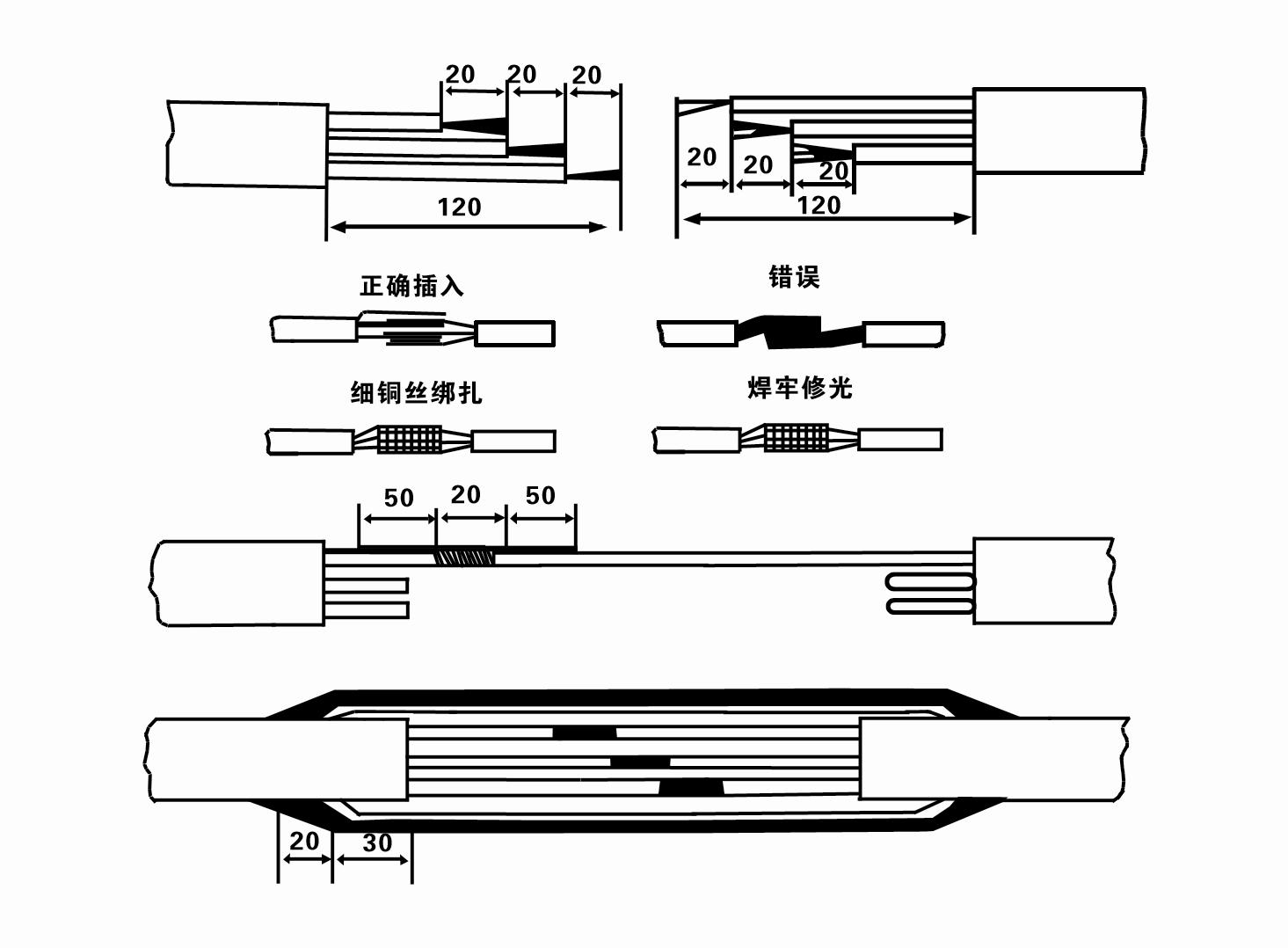
8. З дапамогай мультиметра праверце, ці падключаны трохфазныя правады і ці прыкладна збалансавана супраціўленне пастаяннага току.
9. Праверце, ці не перагружана ланцуг і магутнасць трансфарматара, а затым падключыце выключальнік абароны ад перагрузкі або пускавое абсталяванне. Глядзіце табліцу 2 для канкрэтных мадэляў, а затым выліце вядро вады ў вадзяной помпа з выхаду вадзянога помпы, каб змазаць гумовыя падшыпнікі ў помпе, а затым пастаўце погружной электрычны помпа вертыкальна і ўстойліва. Запуск (не больш за адну секунду) і праверыць, ці адпавядае напрамак рулявога кіравання знаку рулявога кіравання. Калі няма, памяняйце месцамі любыя два раздыма трохфазнага кабеля. Затым усталюйце фільтр і падрыхтуйцеся да спуску ў калодзеж. Пры выкарыстанні ў асаблівых выпадках (напрыклад, канавы, канавы, рэкі, сажалкі, сажалкі і г.д.) электрычны помпа павінен быць надзейна заземлены.
(2) Мантажнае абсталяванне і інструменты:
1. Адна пара ланцугоў грузападымальнасцю больш за дзве тоны.
2. Штатыў вышынёй па вертыкалі не менш за чатыры метры.
3. Дзве падвесныя канаты (драцяныя тросы), якія вытрымліваюць вагу больш за адну тону (вытрымліваюць вагу поўнага камплекта вадзяных помпаў).
4. Устанавіць дзве пары заціскаў (заціскаў).
5. Гаечныя ключы, малаткі, адвёрткі, электраінструменты і інструменты і інш.
(3) Устаноўка электрычнага помпы:
1. Схема ўстаноўкі погружного электрычнага помпы паказана на малюнку 2. Канкрэтныя ўстановачныя памеры паказаны ў табліцы 3 «Спіс усталявальных памераў погружного электрычнага помпы».
2. Погружные электрычныя помпы з напорам менш за 30 метраў можна падняць непасрэдна ў свідравіну з дапамогай шлангаў і драцяных вяровак або іншых канапляных вяровак, якія могуць вытрымаць поўную вагу ўсёй машыны, вадаправодных труб і вады ў трубах.
3. У помпах з напорам больш за 30 метраў выкарыстоўваюцца сталёвыя трубы, паслядоўнасць мантажу наступная:
①Выкарыстоўвайце заціск, каб заціснуць верхні канец часткі вадзянога помпы (рухавік і вадзяной помпа былі злучаныя ў гэты час), падніміце яго з дапамогай падвеснага ланцужка і павольна завяжыце ў калодзеж, пакуль не пастаўце заціск на вусце свідравіны і не зніміце падвесны ланцуг.
② Выкарыстоўвайце іншую пару заціскаў, каб заціснуць трубу, падняць яе з дапамогай падвеснага ланцужка на 15 см ад фланца і павольна апусціце. Паміж фланцам трубы і фланцам помпы Устаўце гумовую пракладку на месца і раўнамерна зацягніце трубу і помпа балтамі, гайкамі і спружыннымі шайбамі.
③ Злёгку прыпадніміце погружной помпа, зніміце заціск на верхнім канцы вадзянога помпы, моцна прывяжыце кабель да вадаправоднай трубы пластыкавай стужкай і павольна завяжыце яго, пакуль заціск не будзе размешчаны на вусце свідравіны.
④Выкарыстайце той жа метад, каб звязаць усе водаправодныя трубы ў калодзеж.
⑤Пасля таго, як вывадны кабель падлучаны да выключальніка кіравання, ён падключаецца да трохфазнай крыніцы сілкавання.
(4) На што варта звярнуць увагу падчас усталёўкі:
1. Калі ў працэсе адпампоўкі выяўляецца з'ява закліноўвання, павярніце або пацягніце вадаправодную трубу, каб пераадолець кропку закліноўвання. Калі розныя меры па-ранейшаму не працуюць, калі ласка, не апускайце помпа з сілай, каб пазбегнуць пашкоджання погружного электрычнага помпы і свідравіны.
2. Падчас мантажу на фланец кожнай трубы трэба пакласці гумовую пракладку і раўнамерна зацягнуць.
3. Калі вадзяной помпа апускаецца ў калодзеж, яго трэба размясціць у сярэдзіне трубы калодзежа, каб помпа не працаваў на сценцы калодзежа на працягу доўгага часу, выклікаючы вібрацыю помпы, а рухавік - падмятанне і гарэнне .
4. Вызначце глыбіню ўстаноўкі вадзяной помпы на дно свідравіны ў залежнасці ад умоў цякучага пяску і глею ў свідравіне. Не закопвайце помпа ў гразь. Адлегласць ад вадзяной помпы да дна свідравіны звычайна не менш за 3 метраў (гл. малюнак 2).
5. Глыбіня ўваходу вады вадзянога помпы павінна быць не менш за 1-1,5 метра ад дынамічнага ўзроўню вады да вузла водазабору (гл. малюнак 2). У адваротным выпадку можна лёгка пашкодзіць падшыпнікі вадзянога помпы.
6. Пад'ём вадзянога помпы не можа быць занадта нізкім. У адваротным выпадку на вусцевым вадаправодзе свідравіны неабходна ўсталяваць засаўку, каб кантраляваць паток помпы ў намінальнай кропцы патоку, каб прадухіліць перагрузку і перагаранне рухавіка з-за вялікіх расходаў.
7. Калі вадзяной помпа працуе, выхад вады павінен быць бесперапынным і раўнамерным, ток павінен быць стабільным (пры намінальных умовах працы, як правіла, не больш за 10% ад намінальнага току), і не павінна быць вібрацыі або шуму. Калі ёсць якая-небудзь ненармальнасць, машыну трэба спыніць, каб высветліць прычыну і ліквідаваць яе.
8. Пры ўсталёўцы звярніце ўвагу на наладу провада зазямлення рухавіка (гл. малюнак 2). Калі вадаправодная труба - гэта сталёвая труба, вядзіце яе ад заціску вусця свідравіны; калі вадаправодная труба з'яўляецца пластыкавай, правядзіце яе ад адзнакі зазямлення электрычнага помпы.
After the installation of the underwater pump, the insulation resistance and three-phase continuity of the switch face should be rechecked, and the connection between the instrument and the start device should be checked for any errors. If there is no problem, you can start to test the machine. After the start, observe whether the indication readings of each instrument are correct. If the rated voltage and current specified on the nameplate are exceeded, observe whether the pump has noise or vibration. If everything is normal, it can be put into operation. After the first operation of the pump for four hours, the motor should be shut down and tested for thermal insulation resistance quickly. Its value should not be less than 0.5 megaohm. After stopping the pump, it should be restarted after an interval of five minutes to prevent the water column in the pipeline from completely reversing and causing the motor to burn out due to excessive current. After the pump is put into normal operation, in order to prolong its service life, it is necessary to check regularly whether the supply voltage, running current and insulation resistance are normal. If the following conditions are found, the machine should be shut down immediately to eliminate the fault: the current exceeds 20% under rated working conditions; the dynamic water level drops to the inlet section, resulting in intermittent drainage; the underwater pump becomes violently vibrating or making noise; the supply voltage is lower than 340 volts; a fuse is blown out; the water pipe is damaged; the motor's thermal insulation resistance to the earth is less than 0.5 megaohm. The sequence of disassembly is: untie the cable fastening, remove the pipeline part, remove the line protection plate, screw down the water discharge bolt and discharge all the water in the motor chamber, remove the filter and loosen the coupling fixing screw of the motor shaft. The sequence of disassembly of the pump is: (see Figure 1) inlet section, impeller, guide housing, impeller, check the valve body. When removing the impeller, use special tools to loosen the taper sleeve of the impeller. Avoid bending the pump shaft and damaging the components throughout the process. The disassembly process of the motor is: (see Figure 1) put the motor on the platform, and remove the bolts, base, shaft head lock nut, thrust plate, key, lower guide plate (transverse bolt), bearing seat, screw knife seat from the bottom of the motor in order (take care not to damage the winding), and finally remove the connecting part and the upper guide bearing seat. Before assembling the unit, the rust and dirt of each part should be cleaned, and the sealant should be applied to each mating surface and fastener, and then assembled in reverse order of disassembly (the movement of the motor shaft after assembly is about one millimeter). After assembly, the coupling should be rotated flexibly and put on the filter for test. Once a year, or if less than a year of operation but has been immersed for two years, the underwater electric pump must be disassembled for maintenance in accordance with Article 5 and replace worn parts to ensure the normal operation and durability of the pump.
1, патушыце ваду ў паражніны рухавіка (асабліва зімой, каб прадухіліць замярзанне рухавіка) і добра завяжыце кабель.
2, store in an indoor room without corrosive substances and gases, with a temperature below 40 °C.
3, пры працяглым выкарыстанні варта звярнуць увагу на прафілактыку іржы погружных помпаў.
- Крыльчатка
- Ўтулка вала
- Гумавая ўтулка вала
-
Ўшчыльняльнае кольца
01 Водазабор глыбокага калодзежа
02 Вышынны водаправод
03 горны водазабеспячэнне
04 вадаправодная вежа
05 Сельскагаспадарчая ірыгацыя
06 абрашэнне саду
07 рачны водазабор
08 бытавая вада

