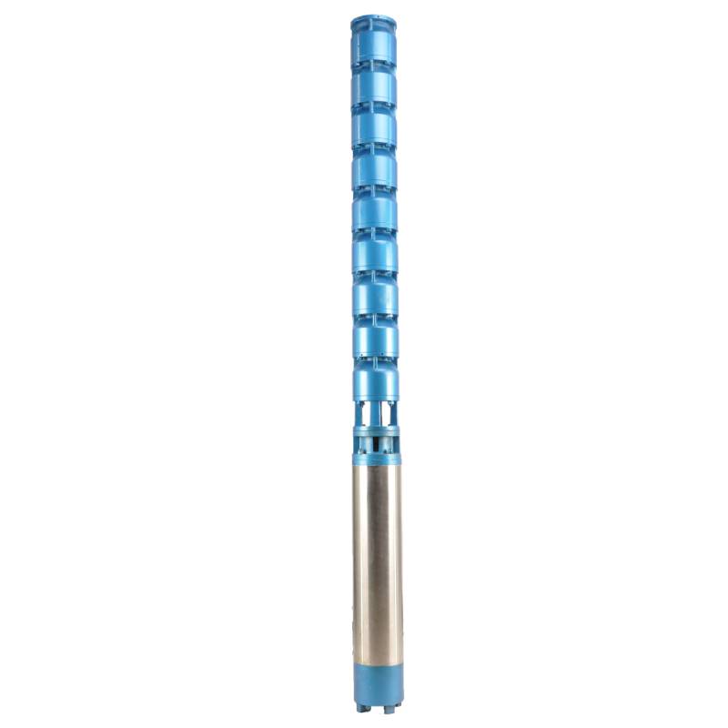
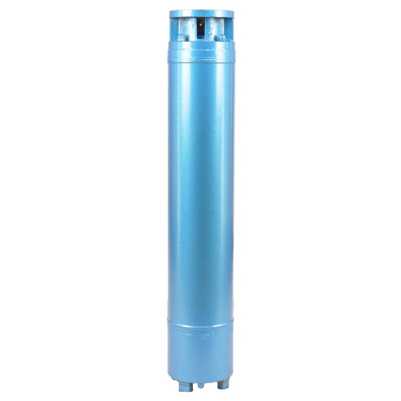
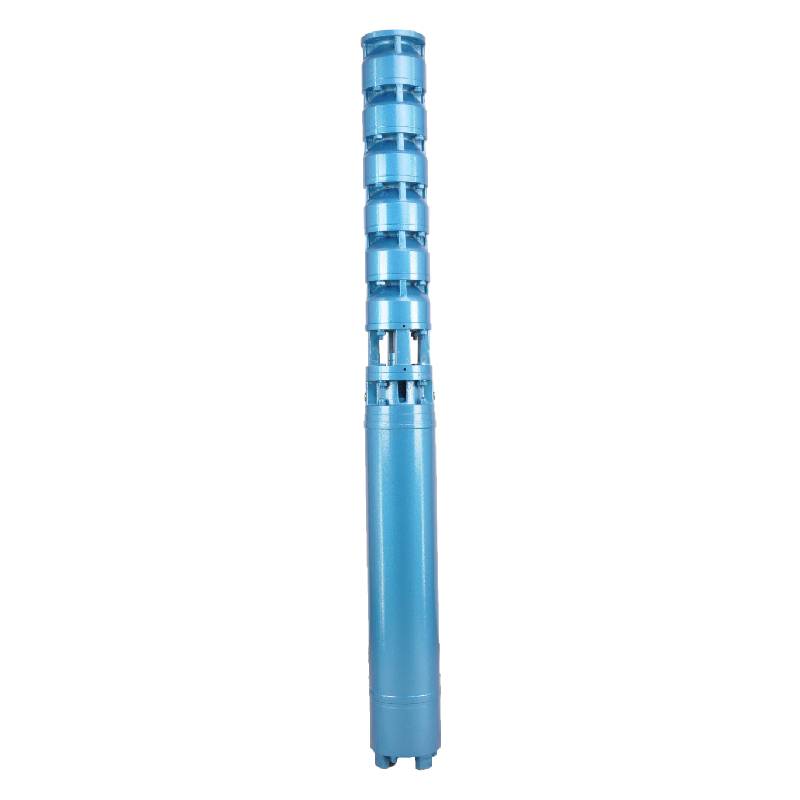
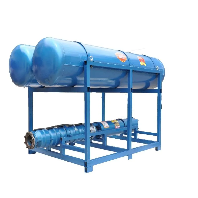
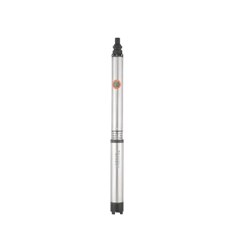
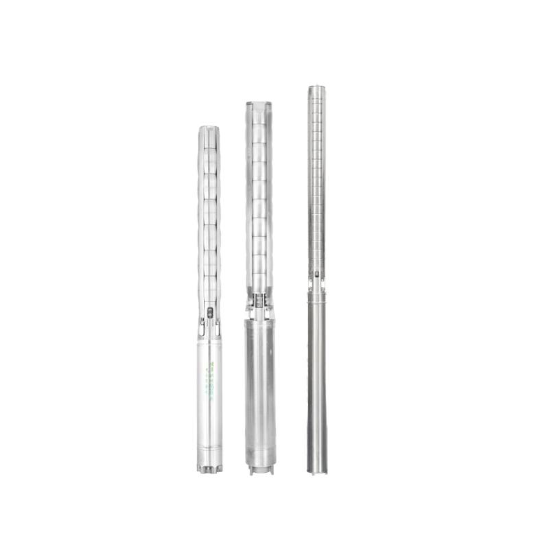
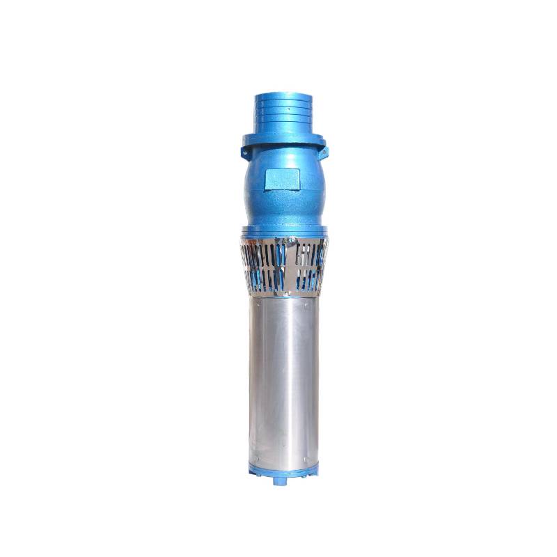
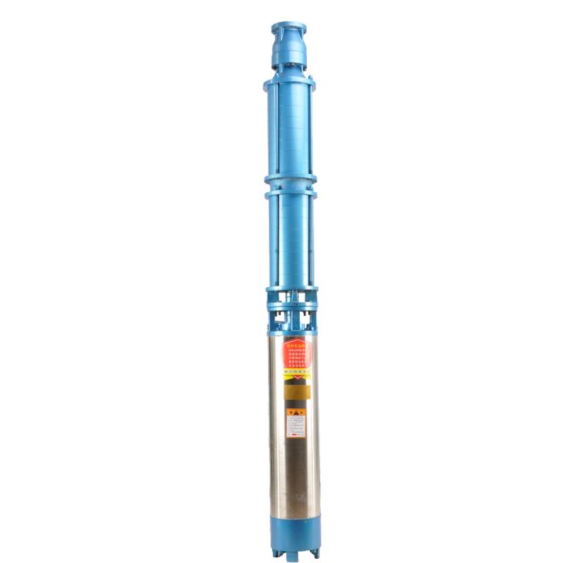
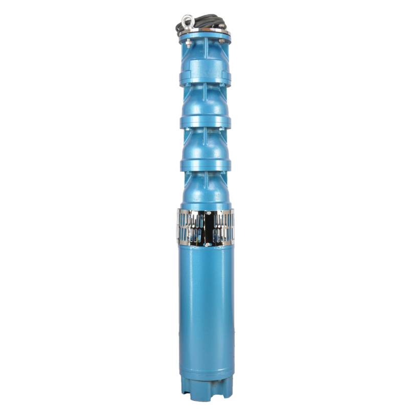
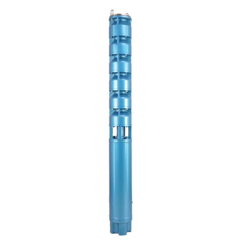
The motor winding adopts special water-resistant wire for frequency conversion winding, which has excellent characteristics such as high frequency stamping resistance, pulse peak voltage stamping resistance and high temperature aging resistance. The frequency conversion winding design ensures the long-term stable conversion operation of the motor between 1HZ-50HZ, making the frequency conversion deep well pump more energy saving and longer service life.
The product is supplied by three-phase AC 380V (tolerance ± 5%), 50HZ (tolerance ± 1%). Applicable water quality conditions include water temperature not exceeding 20 °C, solid impurities content (mass ratio) is not greater than 0.01%, PH value (pH) is 6.5-8.5, hydrogen sulfide content is not more than 1.5mg/L, chloride ion content is not more than 400mg/L. The motor adopts closed or water-filled wet structure. Before use, the internal chamber needs to be filled with clean water to prevent virtual filling. The pump needs to be completely immersed in water, the penetration depth shall not exceed 70m, and the distance from the bottom of the well shall not be less than 3m. The water inlet of the well shall meet the water output and continuous operation requirements of the pump, and the output of the pump shall be controlled at 0.7-1.2 times of the rated flow. The pump shall be used vertically, and the pump must be matched with the cable according to the requirements and equipped with external overload protection device. It is strictly prohibited to conduct no-load test of the pump, and it is necessary to avoid operation without water.
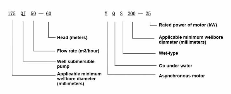
| Malli | Virtaus (m3/h) | Pää (m) |
Rotatingspeed(change/point) | Vesipumppu(%) | Pistorasia halkaisija (mm) |
Soveltuu hyvin halkaisija (mm) |
Arvioitu teho (KW) |
Arvioitu jännite (V) |
Arvioitu virta (A) |
Moottoriteho (%) | power factorcosφ | Yksikkö Säteittäinen enimmäiskoko (mm) |
Huomautus | |||||||||
| 150QJ5-100 | 5 | 100 | 2850 | 58 | 40 | 150 | 3 | 380 | 7.9 | 74.0 | 0.78 | 143 | ||||||||||
| 150QJ5-150 | 5 | 150 | 2850 | 58 | 40 | 150 yläpuolella | 4 | 380 | 10.25 | 75.0 | 0.79 | 143 | ||||||||||
| 150QJ5-200 | 200 | 5.5 | 13.74 | 76.0 | 0.8 | |||||||||||||||||
| 150QJ5-250 | 250 | 7.5 | 18.5 | 77.0 | 0.8 | |||||||||||||||||
| 150QJ5-300 | 300 | 9.2 | 22.12 | 78.0 | 0.81 | |||||||||||||||||
| 150QJ10-50 | 10 | 50 | 2850 | 63 | 50 | 150edellä | 3 | 380 | 7.9 | 74.0 | 0.78 | 143 | ||||||||||
| 150QJ10-66 | 66 | 4 | 10.25 | 75.0 | 0.79 | |||||||||||||||||
| 150QJ10-78 | 78 | 4 | 10.25 | 75.0 | 0.79 | |||||||||||||||||
| 150QJ10-84 | 84 | 5.5 | 13.74 | 76.0 | 0.8 | |||||||||||||||||
| 150QJ10-91 | 91 | 5.5 | 13.74 | 76.0 | 0.8 | |||||||||||||||||
| 150QJ10-100 | 100 | 5.5 | 13.74 | 76.0 | 0.8 | |||||||||||||||||
| 150QJ10-128 | 128 | 7.5 | 18.5 | 77.0 | 0.8 | |||||||||||||||||
| 150QJ10-150 | 150 | 7.5 | 18.5 | 77.0 | 0.8 | |||||||||||||||||
| 150QJ10-200 | 200 | 11 | 26.28 | 78.5 | 0.81 | |||||||||||||||||
| 150QJ10-250 | 250 | 13 | 30.87 | 79.0 | 0.81 | |||||||||||||||||
| 150QJ10-300 | 300 | 15 | 35.62 | 79.0 | 0.81 | |||||||||||||||||
| 150QJ15-33 | 15 | 33 | 2850 | 63 | 50 | 150edellä | 3 | 380 | 7.9 | 74.0 | 0.78 | 143 | ||||||||||
| 150QJ15-42 | 42 | 4 | 10.25 | 75.0 | 0.79 | |||||||||||||||||
| 150QJ15-50 | 50 | 4 | 10.25 | 75.0 | 0.79 | |||||||||||||||||
| 150QJ15-60 | 60 | 5.5 | 13.74 | 76 | 0.8 | |||||||||||||||||
| 150QJ15-65 | 65 | 5.5 | 13.74 | 76.0 | 0.8 | |||||||||||||||||
| 150QJ15-72 | 72 | 5.5 | 13.74 | 76.0 | 0.8 | |||||||||||||||||
| 150QJ15-81 | 81 | 7.5 | 18.5 | 77.0 | 0.8 | |||||||||||||||||
| 150QJ15-90 | 90 | 7.5 | 18.5 | 77.0 | 0.8 | |||||||||||||||||
| 150QJ15-98 | 98 | 7.5 | 18.5 | 77.0 | 0.8 | |||||||||||||||||
| 150QJ15-106 | 106 | 9.2 | 22.12 | 78.0 | 0.81 | |||||||||||||||||
| 150QJ15-114 | 114 | 9.2 | 22.12 | 78.0 | 0.81 | |||||||||||||||||
| 150QJ15-130 | 130 | 11 | 26.28 | 78.5 | 0.81 | |||||||||||||||||
| 150QJ15-146 | 146 | 13 | 30.87 | 79.0 | 0.81 | |||||||||||||||||
| 150QJ15-162 | 162 | 13 | 30.87 | 79.0 | 0.81 | |||||||||||||||||
| 150QJ15-180 | 180 | 15 | 35.62 | 79.0 | 0.81 | |||||||||||||||||
| 150QJ20-26 | 20 | 26 | 2850 | 64 | 50 | 150edellä | 3 | 380 | 7.9 | 74.0 | 0.78 | 143 | ||||||||||
| 150QJ20-33 | 33 | 3 | 7.9 | 74.0 | 0.78 | |||||||||||||||||
| 150QJ20-39 | 20 | 39 | 2850 | 64 | 50 | 150edellä | 4 | 380 | 10.25 | 75.0 | 0.79 | 143 | ||||||||||
| 150QJ20-52 | 52 | 5.5 | 13.74 | 76.0 | 0.8 | |||||||||||||||||
| 150QJ20-65 | 65 | 7.5 | 18.5 | 77.0 | 0.8 | |||||||||||||||||
| 150QJ20-78 | 78 | 7.5 | 18.5 | 77.0 | 0.8 | |||||||||||||||||
| 150QJ20-91 | 91 | 9.2 | 22.12 | 78.0 | 0.81 | |||||||||||||||||
| 150QJ20-98 | 98 | 9.2 | 22.12 | 78.0 | 0.81 | |||||||||||||||||
| 150QJ20-104 | 104 | 11 | 26.28 | 78.5 | 0.81 | |||||||||||||||||
| 150QJ20-111 | 111 | 11 | 26.28 | 78.5 | 0.81 | |||||||||||||||||
| 150QJ20-130 | 130 | 13 | 30.87 | 79.0 | 0.81 | |||||||||||||||||
| 150QJ20-143 | 143 | 13 | 30.87 | 79.0 | 0.81 | |||||||||||||||||
| 150QJ20-156 | 156 | 15 | 35.62 | 79.0 | 0.81 | |||||||||||||||||
| 150QJ20-182 | 182 | 18.5 | 43.12 | 79.5 | 0.82 | |||||||||||||||||
| 150QJ25-24 | 25 | 24 | 2850 | 64 | 65 | 150edellä | 3 | 380 | 7.9 | 74.0 | 0.78 | 143 | ||||||||||
| 150QJ25-32 | 32 | 4 | 10.25 | 75.0 | 0.79 | |||||||||||||||||
| 150QJ25-40 | 40 | 5.5 | 13.74 | 76.0 | 0.8 | |||||||||||||||||
| 150QJ25-48 | 48 | 5.5 | 13.74 | 76.0 | 0.8 | |||||||||||||||||
| 150QJ25-56 | 56 | 7.5 | 18.5 | 77.0 | 0.8 | |||||||||||||||||
| 150QJ25-64 | 64 | 7.5 | 18.5 | 77.0 | 0.8 | |||||||||||||||||
| 150QJ25-72 | 72 | 9.2 | 22.12 | 78.0 | 0.81 | |||||||||||||||||
| 150QJ25-77 | 77 | 9.2 | 22.12 | 78.0 | 0.81 | |||||||||||||||||
| 150QJ25-84 | 84 | 11 | 26.28 | 78.5 | 0.81 | |||||||||||||||||
| 150QJ25-96 | 96 | 11 | 26.28 | 78.5 | 0.81 | |||||||||||||||||
| 150QJ25-104 | 104 | 13 | 30.87 | 79.0 | 0.81 | |||||||||||||||||
| 150QJ25-110 | 110 | 13 | 30.87 | 79.0 | 0.81 | |||||||||||||||||
| 150QJ25-120 | 120 | 15 | 35.62 | 79.0 | 0.81 | |||||||||||||||||
| 150QJ25-128 | 128 | 15 | 35.62 | 79.0 | 0.81 | |||||||||||||||||
| 150QJ25-136 | 136 | 18.5 | 43.12 | 79.5 | 0.82 | |||||||||||||||||
| 150QJ25-154 | 154 | 18.5 | 43.12 | 79.5 | 0.82 | |||||||||||||||||
| 150QJ32-18 | 32 | 18 | 2850 | 66 | 80 | 150edellä | 3 | 380 | 7.9 | 74.0 | 0.78 | 143 | ||||||||||
| 150QJ32-24 | 24 | 4 | 10.25 | 75.0 | 0.79 | |||||||||||||||||
| 150QJ32-30 | 30 | 5.5 | 13.74 | 76.0 | 0.8 | |||||||||||||||||
| 150QJ32-36 | 36 | 5.5 | 13.74 | 76.0 | 0.8 | |||||||||||||||||
| 150QJ32-42 | 32 | 42 | 2850 | 66 | 80 | 150edellä | 7.5 | 380 | 18.5 | 77.0 | 0.8 | 143 | ||||||||||
| 150QJ32-54 | 54 | 9.2 | 22.12 | 78.0 | 0.81 | |||||||||||||||||
| 150QJ32-66 | 66 | 11 | 26.28 | 78.5 | 0.81 | |||||||||||||||||
| 150QJ32-72 | 72 | 13 | 30.87 | 79.0 | 0.81 | |||||||||||||||||
| 150QJ32-84 | 84 | 13 | 30.87 | 79.0 | 0.81 | |||||||||||||||||
| 150QJ32-90 | 90 | 15 | 35.62 | 79.0 | 0.81 | |||||||||||||||||
| 150QJ32-96 | 96 | 15 | 35.62 | 79.0 | 0.81 | |||||||||||||||||
| 150QJ32-114 | 114 | 18.5 | 43.12 | 79.5 | 0.82 | |||||||||||||||||
| 150QJ40-16 | 40 | 16 | 2850 | 66 | 80 | 150edellä | 3 | 380 | 7.9 | 74.0 | 0.78 | 143 | ||||||||||
| 150QJ40-24 | 24 | 5.5 | 13.74 | 76.0 | 0.8 | |||||||||||||||||
| 150QJ40-30 | 30 | 5.5 | 13.74 | 76.0 | 0.8 | |||||||||||||||||
| 150QJ40-40 | 40 | 7.5 | 18.5 | 77.0 | 0.8 | |||||||||||||||||
| 150QJ40-48 | 48 | 9.2 | 22.12 | 78.0 | 0.81 | |||||||||||||||||
| 150QJ40-56 | 56 | 11 | 26.28 | 78.5 | 0.81 | |||||||||||||||||
| 150QJ40-64 | 64 | 13 | 30.87 | 79.0 | 0.81 | |||||||||||||||||
| 150QJ40-72 | 72 | 13 | 30.87 | 79.0 | 0.81 | |||||||||||||||||
| 150QJ40-80 | 80 | 15 | 35.62 | 79.0 | 0.81 | |||||||||||||||||
| 150QJ40-96 | 96 | 18.5 | 43.12 | 79.5 | 0.82 | |||||||||||||||||
| 150QJ50-16 | 50 | 16 | 2850 | 65 | 80 | 150edellä | 4 | 380 | 10.25 | 75.0 | 0.79 | 143 | ||||||||||
| 150QJ50-22 | 22 | 5.5 | 13.74 | 76.0 | 0.8 | |||||||||||||||||
| 150QJ50-28 | 28 | 7.5 | 18.5 | 77.0 | 0.8 | |||||||||||||||||
| 150QJ50-34 | 34 | 9.2 | 22.12 | 78.0 | 0.81 | |||||||||||||||||
| 150QJ50-40 | 40 | 9.2 | 22.12 | 78.0 | 0.81 | |||||||||||||||||
| 150QJ50-46 | 46 | 11 | 26.28 | 78.5 | 0.81 | |||||||||||||||||
| 150QJ50-52 | 52 | 13 | 30.87 | 79.0 | 0.81 | |||||||||||||||||
| 150QJ50-57 | 57 | 15 | 35.62 | 79.0 | 0.81 | |||||||||||||||||
| 150QJ50-74 | 74 | 18.5 | 43.12 | 79.5 | 0.82 | |||||||||||||||||
| 150QJ50-80 | 80 | 18.5 | 43.12 | 79.5 | 0.82 | |||||||||||||||||
| 150QJ63-12 | 63 | 12 | 2850 | 60 | 80 | 150edellä | 4 | 380 | 10.25 | 75.0 | 0.79 | 143 | ||||||||||
| 150QJ63-18 | 18 | 7.5 | 18.5 | 77.0 | 0.8 | |||||||||||||||||
| 150QJ63-30 | 30 | 9.2 | 22.12 | 78.0 | 0.81 | |||||||||||||||||
| 150QJ63-36 | 36 | 11 | 26.28 | 78.5 | 0.81 | |||||||||||||||||
| 150QJ63-42 | 63 | 42 | 2850 | 60 | 80 | 150edellä | 13 | 380 | 30.87 | 79.0 | 0.81 | 143 | ||||||||||
| 150QJ63-48 | 48 | 15 | 35.62 | 79.0 | 0.81 | |||||||||||||||||
| 150QJ63-54 | 54 | 18.5 | 43.12 | 79.5 | 0.82 | |||||||||||||||||
| 150QJ15-220 | 15 | 220 | 2850 | 50 | 150edellä | 18.5 | 380 | 43.12 | 143 | |||||||||||||
| 150QJ15-260 | 260 | 20 | 49.7 | |||||||||||||||||||
| 150QJ15-300 | 300 | 25 | 56.5 | |||||||||||||||||||
| 150QJ20-210 | 20 | 210 | 2850 | 50 | 150edellä | 20 | 380 | 49.7 | 143 | |||||||||||||
| 150QJ20-240 | 240 | 25 | 56.5 | |||||||||||||||||||
| 150QJ20-290 | 290 | 30 | 66.6 | |||||||||||||||||||
| 150QJ25-175 | 25 | 175 | 2850 | 65 | 150edellä | 20 | 49.7 | 143 | ||||||||||||||
| 150QJ25-200 | 200 | 30 | 66.6 | |||||||||||||||||||
| 150QJ25-290 | 290 | 37 | 82.1 | |||||||||||||||||||
| 150QJ32-120 | 32 | 120 | 2850 | 80 | 150edellä | 20 | 380 | 49.7 | 143 | |||||||||||||
| 150QJ32-132 | 132 | 25 | 56.5 | |||||||||||||||||||
| 150QJ32-156 | 156 | 30 | 66.6 | |||||||||||||||||||
| 150QJ32-190 | 190 | 37 | 82.1 | |||||||||||||||||||
| 150QJ32-240 | 240 | 45 | 96.9 | |||||||||||||||||||
| 150QJ40-110 | 40 | 110 | 2850 | 80 | 150edellä | 20 | 380 | 49.7 | 143 | |||||||||||||
| 150QJ40-121 | 121 | 25 | 56.5 | |||||||||||||||||||
| 150QJ40-143 | 143 | 30 | 66.6 | |||||||||||||||||||
| 150QJ40-176 | 176 | 37 | 82.1 | |||||||||||||||||||
| 150QJ40-220 | 220 | 45 | 96.9 | |||||||||||||||||||
| 150QJ50-100 | 50 | 100 | 2850 | 80 | 150edellä | 20 | 380 | 49.7 | 143 | |||||||||||||
| 150QJ50-110 | 110 | 25 | 56.5 | |||||||||||||||||||
| 150QJ50-130 | 130 | 30 | 66.6 | |||||||||||||||||||
| 150QJ50-160 | 160 | 37 | 82.1 | |||||||||||||||||||
| 150QJ50-200 | 200 | 45 | 96.9 | |||||||||||||||||||
This well submersible pump is a pump suitable for clean water. It is strictly prohibited to pump sediment and turbid water in new wells. The voltage level of the pump is 380/50HZ. Other voltage levels of the submersible motor need to be customized. Underground cables must be waterproof and must be equipped with starting equipment, such as distribution box, etc. The starting equipment should have common motor comprehensive protection functions, such as short circuit overload protection, phase loss protection, undervoltage protection, grounding protection and idling protection, etc. Under abnormal circumstances, the protection device should be tripped in time. In the process of installation and use, the pump must be reliably grounded. It is prohibited to push and pull the switch when the hands and feet are wet. The power must be cut off before installation and maintenance of the pump. The place where the pump is used must set up a clear "anti-electric shock" mark. Before going down the well or installation, the motor must be filled with distilled water or non-corrosive cool water, and the water inlet and outlet screws must be tightened. When testing the pump, water must be injected into the pump chamber to lubricate the rubber bearings. The instant start shall not exceed one second to check whether the direction is correct. It is necessary to pay attention to the safety of the pump when it is erected to prevent it from toppling and hurting people. Strictly in accordance with the provisions of the pump lift and flow range of use, so as not to have a large flow in the low lift pump or a large pull in the high lift, causing extreme wear of thrust bearings and other components, resulting in motor overload burn. After the pump into the well, the measurement of the motor and ground insulation resistance, not less than 100M. After the start, regular observation of voltage and current, and check whether the motor winding insulation meets the requirements; if the pump storage location temperature is below freezing, storage should discharge the water in the motor cavity, to prevent the water in the motor cavity due to low temperature and freeze damage the motor.
Lyhyt esittely rakenteesta: pumpun osa koostuu pääasiassa pumpun akselista, juoksupyörästä, suuntakuoresta, kumilaakerista, takaiskuventtiilin rungosta (valinnaiset osat) ja muista komponenteista. Moottorin osa koostuu pääasiassa pohjasta, paineensäätökalvosta, painelaakerista, painelevystä, alemmasta ohjauslaakerin istukasta, staattorista, roottorista, ylemmästä ohjauslaakerin istukasta, hiekkarenkaasta, vedenottoosasta, kaapelista ja muista komponenteista.
Tuotteen pääominaisuuksiin kuuluvat:
1.The motor is a water-filled wet submersible three-phase asynchronous motor, the motor cavity is full of clean water, used to cool the motor and lubricate the bearing, the pressure regulating film at the bottom of the motor is used to adjust the expansion and contraction pressure difference of the water inside the body caused by the change of the temperature rise of the motor.
2.In order to prevent the sand in the well water from entering the motor, the upper end of the motor shaft is equipped with two oil seals, and a sand ring is installed to form a sand prevention structure.
3.In order to prevent the pump shaft from running up when starting, the pump shaft and the motor shaft are connected by a coupling, and an upper thrust bearing is installed at the lower part of the motor.
4.The lubrication of the motor and the pump bearing is water lubrication.
5.The motor stator winding is made of high quality submersible motor winding wire, with high insulation performance.
6.The pump is designed by computer CAD, with simple structure and good technical performance.

(1) Valmistelu ennen asennusta:
1. Tarkista, täyttääkö uppopumppu käsikirjassa määritellyt käyttöehdot ja laajuuden.
2. Käytä paksua obiektia, jonka halkaisija on yhtä suuri kuin uppopumpun suurin ulkohalkaisija, ja mittaa, mahtuuko porausreiän sisähalkaisija uppopumppuun, ja mittaa, täyttääkö kaivon syvyys asennusvaatimukset.
3. Tarkista, onko kaivon reikä puhdas ja onko kaivon vesi sameaa. Älä koskaan käytä upotettavaa sähköpumppua Welor-pumpun mudan ja hiekkaveden pesemiseen välttääksesi upotettavan sähköpumpun ennenaikaiset vauriot.
4. Tarkista, onko hitsauspään asennuspuristimen asento sopiva ja kestääkö se koko yksikön laadun
5. Tarkista, ovatko uppopumpun komponentit valmiit ja asennettu oikein käsikirjan asennuskaavion mukaisesti. Irrota suodatinverkko ja käännä kytkintä nähdäksesi, pyöriikö se joustavasti
6. Irrota vesiruuvi ja täytä moottorin ontelo puhtaalla, syövyttämättömällä vedellä (huomaa, että täytä se), kiristä sitten vesiruuvi. 12 tunnin vedenruiskutuksen jälkeen moottorin eristysvastuksen ei tulisi olla alle 150M Q mitattuna 500 V:n ravistuspöydällä.
7. Cable joint, cut off a 120mm rubber sleeve from one end of the outgoing cable and the matching cable with an electrician's knifethen stagger the length of the three core wires in a stepped shape, peel off a 20mm copper core, scrape of the oxide layer on theoutside of the copper wire with a knife or sand cloth, and insert the two connected wire ends in palirs.After tying the layer tightly with fine copper wire, solder it thoroughly and firmly, and sand of any. burrs on the surface. Then, forthe three joints, use polyvester insulation tape to wrap them in a semi stacked manner for three lavers. Wrap the two ends of thewrapping layer tightywith nyion thread,and then use a semi stacked method to wrap the tape for three layers. Wrap the outellayer with high-pressure insulation tape for three layers. Finally, fold the threestrands together and repeatedly wrap them for fivelayers with high-pressure tape. Each layer must be tightly tied, and the interlayer joints must be tight and fimm to prevent water frompenetrating and damaging the insulation, After wrapping, soak in water at room temperature of 20 ’c for 12 hours, and measurethe insulation resistance with a shaking table, which should not be less than 100M Ω
Liitteenä oleva kaapelin kytkentäkaavio on seuraava: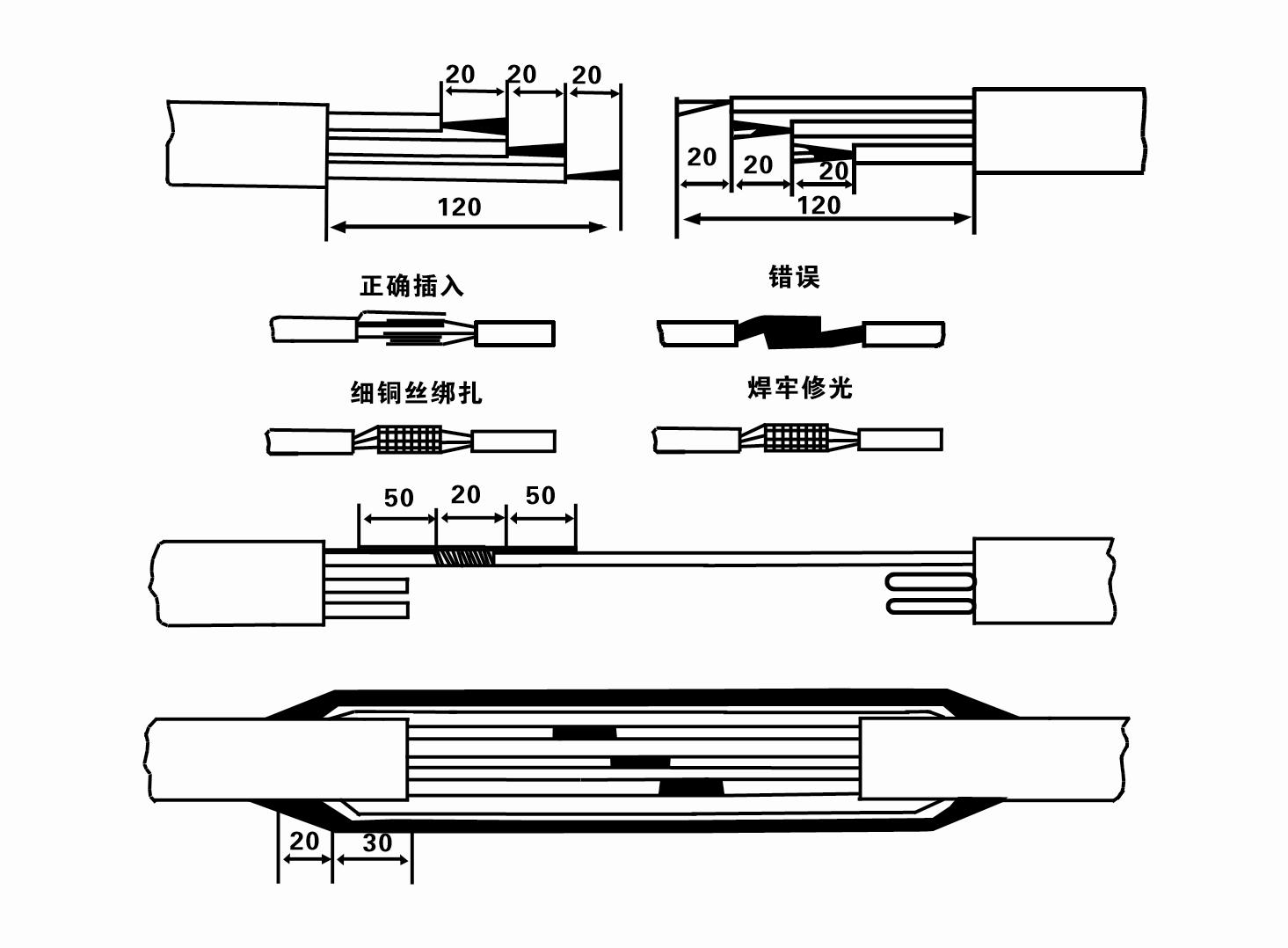
8. Tarkista yleismittarilla, onko kolmivaihejohdot kytketty ja onko tasavirtavastus suunnilleen tasapainossa.
9. Tarkista, onko piiri ja muuntajan kapasiteetti ylikuormitettu, ja kytke sitten ylikuormitussuojakytkin tai käynnistyslaitteisto. Katso taulukosta 2 tietyt mallit ja kaada sitten ämpäri vettä vesipumppuun vesipumpun ulostuloaukosta pumpun kumilaakerien voitelemiseksi ja aseta sitten upotettava sähköpumppu pystyasentoon ja vakaasti. Käynnistä (enintään sekunti) ja tarkista, onko ohjaussuunta yhdenmukainen ohjauskyltin kanssa. Jos ei, vaihda mitkä tahansa kaksi kolmivaiheisen kaapelin liitintä. Asenna sitten suodatin ja valmistaudu menemään kaivoon. Jos sähköpumppua käytetään erikoistilanteissa (kuten ojissa, ojissa, joissa, lammikoissa, lammikoissa jne.), sähköpumpun on oltava luotettavasti maadoitettu.
(2) Asennuslaitteet ja -työkalut:
1. Yksi nostoketjupari yli kahdelle tonnille.
2. Kolmijalka, jonka pystykorkeus on vähintään neljä metriä.
3. Kaksi ripustusköyttä (vaijeriköyttä), jotka kestävät yli yhden tonnin painon (kestävät koko vesipumppusarjan painon).
4. Asenna kaksi paria puristimia (lastoja).
5. Avaimet, vasarat, ruuvimeisselit, sähkötyökalut ja -välineet jne.
(3) Sähköpumpun asennus:
1. Upotettavan sähköpumpun asennuskaavio on esitetty kuvassa 2. Erityiset asennusmitat on esitetty taulukossa 3 "Upotettavan sähköpumpun asennusmittojen luettelo".
2. Upotettavat sähköpumput, joiden korkeus on alle 30 metriä, voidaan nostaa suoraan kaivoon käyttämällä letkuja ja vaijereita tai muita hamppuköysiä, jotka kestävät koko koneen, vesiputkien ja putkissa olevan veden koko painon.
3. Pumput, joiden nostokorkeus on yli 30 metriä, käyttävät teräsputkia, ja asennusjärjestys on seuraava:
①Kiinnitä vesipumpun osan yläpää puristimella (moottori ja vesipumppu on kytketty tällä hetkellä), nosta se ripustusketjulla ja sido se hitaasti kaivoon, kunnes Aseta puristin kaivon päähän ja poista riippuva ketju.
② Käytä toista puristinparia putken kiinnittämiseen, nosta se riippuketjulla 15 cm:n päähän laipasta ja laske se hitaasti alas. Putken laipan ja pumpun laipan väliin Aseta kumityyny paikoilleen ja kiristä putki ja pumppu tasaisesti pulteilla, muttereilla ja jousialuslevyillä.
③ Nosta uppopumppua hieman, irrota puristin vesipumpun yläpäästä, sido kaapeli tiukasti vesiputkeen muoviteipillä ja sido se hitaasti alas, kunnes puristin asettuu kaivon päähän.
④Kiinnitä kaikki vesiputket kaivoon samalla tavalla.
⑤Kun ulostulokaapeli on kytketty ohjauskytkimeen, se liitetään kolmivaiheiseen virtalähteeseen.
(4) Huomioitavaa asennuksen aikana:
1. Jos pumppausprosessin aikana havaitaan juuttumisilmiö, käännä tai vedä vesiputkea päästäksesi eroon tukoskohdasta. Jos useat toimenpiteet eivät vieläkään auta, älä paina pumppua väkisin alas, jotta uppopumppu ja kaivo eivät vaurioidu.
2. Asennuksen aikana kumityyny tulee asettaa jokaisen putken laippaan ja kiristää tasaisesti.
3. Kun vesipumppu lasketaan kaivoon, se tulee sijoittaa kaivon putken keskelle, jotta pumppu ei pääse pyörimään kaivon seinää vasten pitkään, jolloin pumppu tärisee ja moottori lakaise ja palaa. .
4. Määritä vesipumpun syvyys kaivon pohjaan kaivon virtaavan hiekka- ja lieteolosuhteiden mukaan. Älä hauta pumppua mutaan. Etäisyys vesipumpusta kaivon pohjaan on yleensä vähintään 3 metriä (katso kuva 2).
5. Vesipumpun veden sisääntulosyvyyden tulee olla vähintään 1-1,5 metriä dynaamisesta vedenpinnasta vedentulon solmuun (katso kuva 2). Muuten vesipumpun laakerit voivat vaurioitua helposti.
6. Vesipumpun nosto ei saa olla liian matala. Muussa tapauksessa kaivon pään vesiputkeen on asennettava sulkuventtiili, joka ohjaa pumpun virtausta nimellisvirtauspisteessä, jotta moottori ei ylikuormituisi ja palaisi pois suurten virtausnopeuksien takia.
7. Kun vesipumppu on käynnissä, veden tulee olla jatkuvaa ja tasaista, virran tulee olla vakaa (nimellisissä käyttöolosuhteissa, yleensä enintään 10 % nimellisvirrasta), eikä siinä saa olla tärinää tai melua. Jos havaitaan poikkeavuuksia, kone on pysäytettävä syyn selvittämiseksi ja sen poistamiseksi.
8. Kiinnitä asennuksen yhteydessä huomiota moottorin maadoitusjohtimen asentoon (katso kuva 2). Kun vesiputki on teräsputki, johda se kaivonpään puristimesta; kun vesiputki on muoviputki, johda se sähköpumpun maadoitusmerkistä.
1.submersible pump installation is complete, re-check the insulation resistance and three-phase conduction from the switch, check the instrument and start the equipment connection error, if there is no problem, can start the trial, after the start of the instrument indicating readings whether more than the nameplate stipulated rated voltage and current, observe the pump noise and vibration phenomenon, everything is normal can be put into operation.
2.pump operation for the first four hours, should be shut down quickly test the thermal insulation resistance of the motor, the value should not be less than 0.5 megaohm.
3.pump shutdown, should be started after an interval of five minutes, to prevent the water column in the pipe has not completely reflux caused by excessive motor current and burnout.
4.pump into normal operation, in order to prolong its service life, to check the supply voltage, working current and insulation resistance is normal, if found the following situation, should immediately shut down troubleshooting.
1.in the rated condition, the current is more than20%.
2.dynamic water level to the water inlet section, causing intermittent water.
3.submersible pump severe vibration or noise.
4.supply voltage is lower than 340 volts.
5.fuse burned out a phase.
6.water pipe damage.
7.motor to the thermal insulation resistance is less than 0.5 megaohm. 5. The product is a pump unit with easy disassembly function, with simple steps of disassembly, so that users can easily maintain and clean. The disassembly steps include unraveling the cable rope, taking down the pipeline part and the line protection plate, unloosening the water discharge bolt, excluding all the water in the motor chamber, removing the filter and loosening the coupling fixing screw fixing the motor shaft, unscrewing the bolt connecting the water inlet section and the motor, separating the pump and the motor (note that the unit should be leveled when separating to prevent the bending of the pump shaft), the disassembly sequence of the pump is: water inlet section, impeller, shunt shell, impeller, and cleaning the valve body. When disassembling the impeller, use special tools to loosen the conical sleeve fixing the impeller. In the whole disassembly process, avoid bending the pump shaft and damaging various parts. The disassembly process of the motor is: put the motor on the platform, and remove the nuts, base, shaft head lock nut, thrust plate, key, and lower guide rail from the bottom of the motor in order. Bearing seat, tie rod bolt, and then take out the rotor (be careful not to damage the wiring harness) and finally remove the connecting section and the upper guide bearing seat. Before assembling the unit, the rust and dirt of each part should be cleaned, and the sealant should be coated on each mating surface and fastener, and then the assembly should be carried out in reverse order according to the disassembly (the movement of the motor shaft after assembly is about 1 mm). After the assembly is completed, the coupling should be flexibly rotated, and then the filter should be put on for machine test. This pump unit is not only convenient and easy to use, but also has detailed instructions, which provides users with convenient maintenance experience. 6. Submersible electric pump every operation for one year, or less than one year but the diving time has reached two years, should be put out of the well according to Article 5 for disassembly and maintenance, and replace the worn parts.
1, sammuta vesi moottorin ontelosta (etenkin talvella moottorin jäätymisen estämiseksi) ja sido kaapeli hyvin.
2, store in an indoor room without corrosive substances and gases, with a temperature below 40 °C.
3, pitkäaikaisessa käytössä tulee kiinnittää huomiota uppopumppujen ruosteenestoon.
- Juoksupyörä
- Akseliholkki
- Akselin kumiholkki
-
Tiivisterengas
01 Syvän kaivon vedenotto
02 Korkean rakennuksen vesihuolto
03 vuoren vesihuolto
04 torni vesi
05 Maatalouden kastelu
06 puutarhan kastelu
07 joen vedenotto
08 käyttövesi

