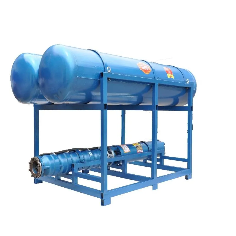
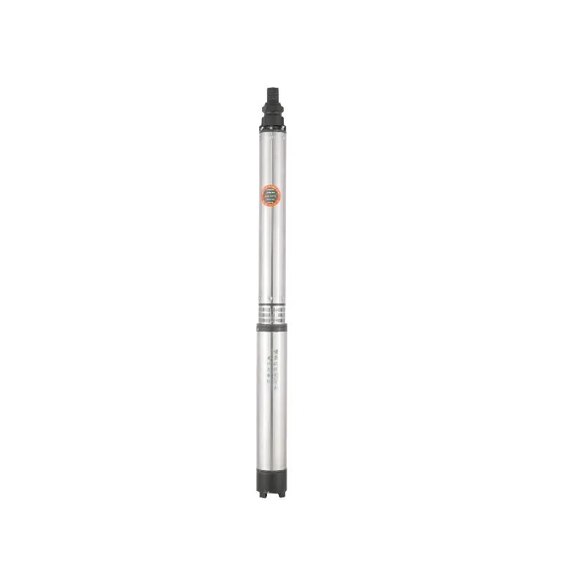
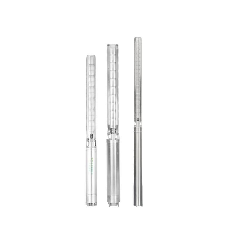
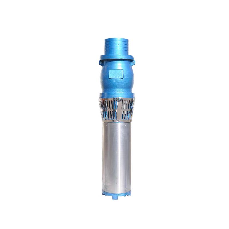
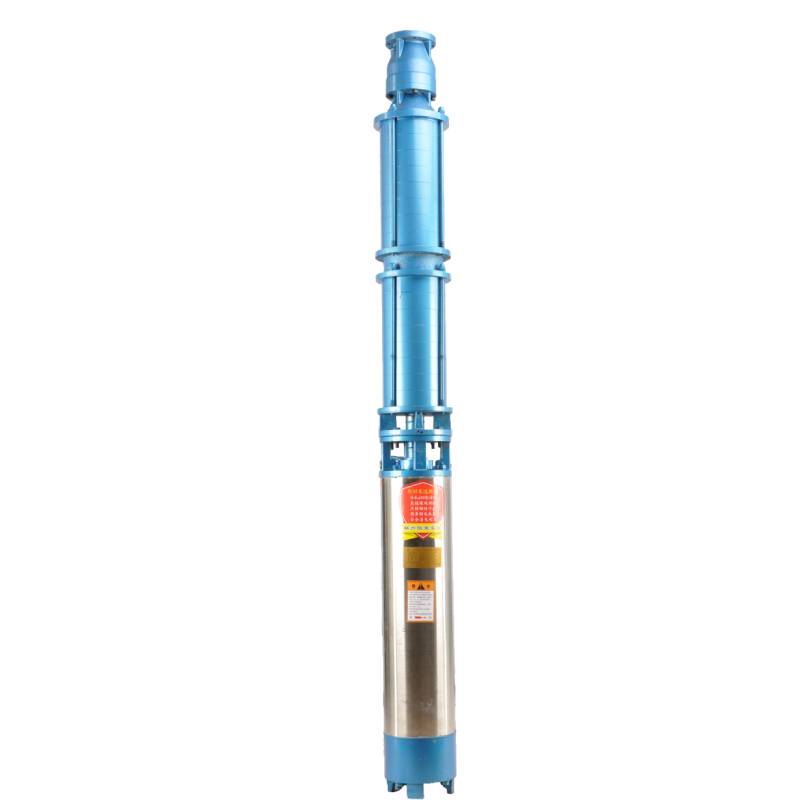
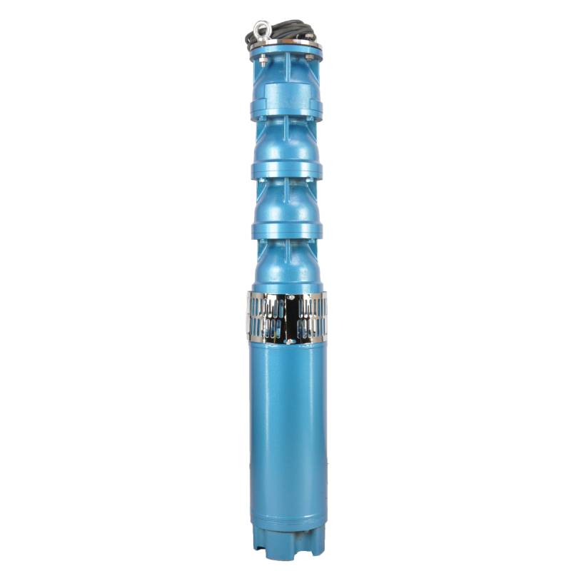
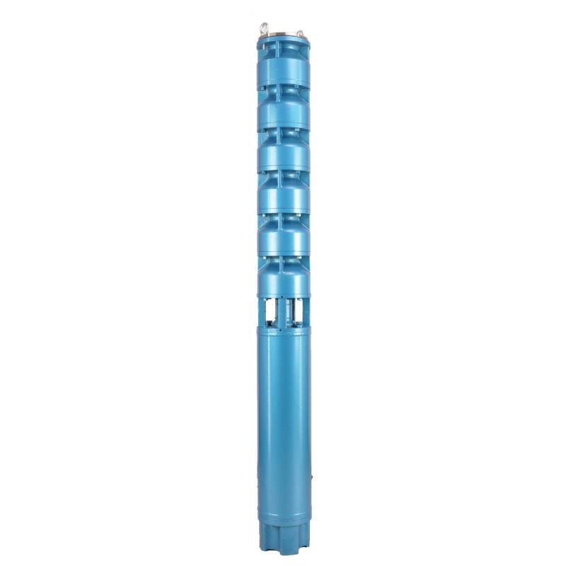
This product adopts variable frequency winding design, ensuring the motor stable long-term conversion operation between 1HZ-50HZ. Its characteristics of energy saving and prolonged service life make it an ideal choice. Through this design, users can achieve efficient energy utilization while prolonging the service life of the product, which meets the modern society's demand for environmental protection and sustainable development. Whether for industrial production or home use, this product will bring users more convenient and efficient experience, becoming the leading choice in the industry.
This three-phase AC 380V (tolerance ± 5%), 50HZ (tolerance ± 1%) submersible pump is a reliable pump equipment, can be used in a variety of application scenarios. In terms of the use of conditions, to ensure good water quality, including water temperature is not higher than 20 °C, solid impurities content is not more than 0.01%, pH value is 6.5-8.5, hydrogen sulfide content is not more than 1.5mg / L, chloride ion content is not more than 400mg / L. The motor adopts a closed or water-filled wet structure, the inner cavity must be filled with clean water before use to prevent false filling. The pump must be completely immersed in water, and the immersion depth shall not exceed 70m, the distance from the bottom of the pump and the bottom of the well shall not be less than 3m. The water source shall meet the requirements of the pump inflow and continuous operation, the pump water control in the rated flow of 0.7-1.2 times. The well must be vertical, the pump can not be used horizontally or tilted, only vertical use. The pump must be equipped with cables and external overload protection device as required. It is strictly prohibited to dry turn the pump test. The design of the equipment is safe and reliable, meets the use of standards, is an indispensable ideal choice in all kinds of engineering projects and industrial applications.
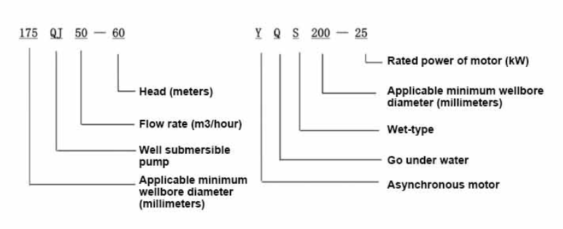
| Model | Flow (m3/h) | Head (m) |
Rotatingspeed(change/point) | Waterpump(%) | Outlet diameter (mm) |
Applicable well diameter(mm) |
Rated power(KW) |
Rated voltage(V) |
Rated current(A) |
Motorefficiency (%) | power factorcosφ | Unit Radial Maximu size(mm) |
Remark | |||||||||
| 200QJ20-40 | 20 | 40 | 2850 | 66 | 50 | 200above | 4 | 380 | 10.1 | 76.0 | 0.79 | 184 | ||||||||||
| 200QJ20-54 | 54 | 5.5 | 13.6 | 77.0 | 0.8 | |||||||||||||||||
| 200QJ20-81 | 81 | 7.5 | 18.0 | 78.0 | 0.81 | |||||||||||||||||
| 200QJ20-93 | 93 | 9.2 | 21.7 | 78.5 | 0.82 | |||||||||||||||||
| 200QJ20-108 | 108 | 11 | 25.8 | 79.0 | 0.82 | |||||||||||||||||
| 200QJ20-121 | 121 | 13 | 29.8 | 80.0 | 0.83 | |||||||||||||||||
| 200QJ20-148 | 148 | 15 | 33.9 | 81.0 | 0.83 | |||||||||||||||||
| 200QJ20-175 | 175 | 18.5 | 41.6 | 81.5 | 0.83 | |||||||||||||||||
| 200QJ20-202 | 202 | 22 | 48.2 | 82.5 | 0.84 | |||||||||||||||||
| 200QJ20-243 | 243 | 25 | 54.5 | 83.0 | 0.84 | |||||||||||||||||
| 200QJ20-270 | 270 | 30 | 65.4 | 83.0 | 0.84 | |||||||||||||||||
| 200QJ20-360 | 360 | 37 | 79.7 | 84.0 | 0.84 | |||||||||||||||||
| 200QJ20-442 | 442 | 45 | 96.9 | 84.0 | 0.84 | |||||||||||||||||
| 200QJ25-28 | 25 | 28 | 2850 | 68 | 65 | 200above | 4 | 380 | 10.1 | 76.0 | 0.79 | 184 | ||||||||||
| 200QJ25-42 | 42 | 5.5 | 13.6 | 77.0 | 0.8 | |||||||||||||||||
| 200QJ25-56 | 56 | 7.5 | 18.0 | 78.0 | 0.81 | |||||||||||||||||
| 200QJ25-70 | 70 | 9.2 | 21.7 | 78.5 | 0.82 | |||||||||||||||||
| 200QJ25-98 | 98 | 11 | 25.8 | 79.0 | 0.82 | |||||||||||||||||
| 200QJ25-112 | 25 | 112 | 2850 | 68 | 65 | 200above | 13 | 380 | 29.8 | 80.0 | 0.83 | 184 | ||||||||||
| 200QJ25-126 | 126 | 15 | 33.9 | 81.0 | 0.83 | |||||||||||||||||
| 200QJ25-154 | 154 | 18.5 | 41.6 | 81.5 | 0.83 | |||||||||||||||||
| 200QJ25-182 | 182 | 22 | 48.2 | 82.5 | 0.84 | |||||||||||||||||
| 200QJ25-210 | 210 | 25 | 54.5 | 83.0 | 0.84 | |||||||||||||||||
| 200QJ25-252 | 252 | 30 | 65.4 | 83.0 | 0.84 | |||||||||||||||||
| 200QJ25-308 | 308 | 37 | 79.7 | 84.0 | 0.84 | |||||||||||||||||
| 200QJ25-378 | 378 | 45 | 96.9 | 84.0 | 0.84 | |||||||||||||||||
| 200QJ32-26 | 32 | 26 | 2850 | 70 | 80 | 200above | 4 | 380 | 10.1 | 76.0 | 0.79 | 184 | ||||||||||
| 200QJ32-39 | 39 | 5.5 | 13.6 | 77.0 | 0.8 | |||||||||||||||||
| 200QJ32-52 | 52 | 7.5 | 18.0 | 78.0 | 0.81 | |||||||||||||||||
| 200QJ32-65 | 65 | 9.2 | 21.7 | 78.5 | 0.82 | |||||||||||||||||
| 200QJ32-78 | 78 | 11 | 25.8 | 79.0 | 0.82 | |||||||||||||||||
| 200QJ32-91 | 91 | 13 | 29.8 | 80.0 | 0.83 | |||||||||||||||||
| 200QJ32-104 | 104 | 15 | 33.9 | 81.0 | 0.83 | |||||||||||||||||
| 200QJ32-130 | 130 | 18.5 | 41.6 | 81.5 | 0.83 | |||||||||||||||||
| 200QJ32-143 | 143 | 22 | 48.2 | 82.5 | 0.84 | |||||||||||||||||
| 200QJ32-169 | 169 | 25 | 54.5 | 83.0 | 0.84 | |||||||||||||||||
| 200QJ32-195 | 195 | 30 | 65.4 | 83.0 | 0.84 | |||||||||||||||||
| 200QJ32-247 | 247 | 37 | 79.7 | 84.0 | 0.84 | |||||||||||||||||
| 200QJ32-299 | 299 | 45 | 96.9 | 84.0 | 0.84 | |||||||||||||||||
| 200QJ40-26 | 40 | 26 | 2850 | 72 | 80 | 200above | 5.5 | 380 | 13.6 | 77.0 | 0.8 | 184 | ||||||||||
| 200QJ40-39 | 39 | 7.5 | 18.0 | 78.0 | 0.81 | |||||||||||||||||
| 200QJ40-52 | 52 | 9.2 | 21.7 | 78.5 | 0.82 | |||||||||||||||||
| 200QJ40-65 | 65 | 11 | 25.8 | 79.0 | 0.82 | |||||||||||||||||
| 200QJ40-78 | 78 | 15 | 33.9 | 81.0 | 0.83 | |||||||||||||||||
| 200QJ40-104 | 104 | 18.5 | 41.6 | 81.5 | 0.83 | |||||||||||||||||
| 200QJ40-117 | 117 | 22 | 48.2 | 82.5 | 0.84 | |||||||||||||||||
| 200QJ40-143 | 143 | 25 | 54.5 | 83.0 | 0.84 | |||||||||||||||||
| 200QJ40-169 | 169 | 30 | 65.4 | 83.0 | 0.84 | |||||||||||||||||
| 200QJ40-208 | 208 | 37 | 79.7 | 84.0 | 0.84 | |||||||||||||||||
| 200QJ40-247 | 247 | 45 | 96.9 | 84.0 | 0.84 | |||||||||||||||||
| 200QJ50-26 | 50 | 26 | 2850 | 74 | 80 | 200above | 5.5 | 380 | 13.6 | 77.0 | 0.8 | 184 | ||||||||||
| 200QJ50-39 | 39 | 9.2 | 21.7 | 78.5 | 0.82 | |||||||||||||||||
| 200QJ50-52 | 52 | 11 | 25.8 | 79.0 | 0.82 | |||||||||||||||||
| 200QJ50-65 | 65 | 15 | 33.9 | 81.0 | 0.83 | |||||||||||||||||
| 200QJ50-78 | 78 | 18.5 | 41.6 | 81.5 | 0.83 | |||||||||||||||||
| 200QJ50-91 | 91 | 22 | 48.2 | 82.5 | 0.84 | |||||||||||||||||
| 200QJ50-104 | 104 | 25 | 54.5 | 83.0 | 0.84 | |||||||||||||||||
| 200QJ50-130 | 130 | 30 | 65.4 | 83.0 | 0.84 | |||||||||||||||||
| 200QJ50-156 | 156 | 37 | 79.7 | 84.0 | 0.84 | |||||||||||||||||
| 200QJ50-208 | 208 | 45 | 96.9 | 84.0 | 0.84 | |||||||||||||||||
| 200QJ63-24 | 63 | 24 | 2850 | 74 | 80 | 200above | 7.5 | 380 | 18.0 | 78.0 | 0.81 | 184 | ||||||||||
| 200QJ63-36 | 36 | 11 | 25.8 | 79.0 | 0.82 | |||||||||||||||||
| 200QJ63-60 | 60 | 18.5 | 41.6 | 81.5 | 0.83 | |||||||||||||||||
| 200QJ63-72 | 72 | 22 | 48.2 | 82.5 | 0.84 | |||||||||||||||||
| 200QJ63-84 | 84 | 25 | 54.5 | 83.0 | 0.84 | |||||||||||||||||
| 200QJ63-96 | 96 | 30 | 65.4 | 83.0 | 0.84 | |||||||||||||||||
| 200QJ63-120 | 120 | 37 | 79.7 | 84.0 | 0.84 | |||||||||||||||||
| 200QJ63-144 | 144 | 45 | 96.9 | 84.0 | 0.84 | |||||||||||||||||
| 200QJ80-22 | 80 | 22 | 2850 | 75 | 100 | 200above | 7.5 | 380 | 18.0 | 78.0 | 0.81 | 184 | ||||||||||
| 200QJ80-33 | 33 | 11 | 25.8 | 79.0 | 0.82 | |||||||||||||||||
| 200QJ80-44 | 44 | 15 | 33.9 | 81.0 | 0.83 | |||||||||||||||||
| 200QJ80-55 | 55 | 18.5 | 41.6 | 81.5 | 0.83 | |||||||||||||||||
| 200QJ80-66 | 66 | 22 | 48.2 | 82.5 | 0.84 | |||||||||||||||||
| 200QJ80-88 | 88 | 30 | 65.4 | 83.0 | 0.84 | |||||||||||||||||
| 200QJ80-99 | 99 | 37 | 79.7 | 84.0 | 0.84 | |||||||||||||||||
| 200QJ80-121 | 121 | 45 | 96.9 | 84.0 | 0.84 | |||||||||||||||||
| 200QJ100-18 | 100 | 18 | 2850 | 75 | 100 | 200above | 9.2 | 380 | 21.7 | 78.5 | 0.82 | 184 | ||||||||||
| 200QJ100-27 | 27 | 13 | 29.8 | 80.0 | 0.83 | |||||||||||||||||
| 200QJ100-36 | 36 | 18.5 | 41.6 | 81.5 | 0.83 | |||||||||||||||||
| 200QJ100-45 | 45 | 22 | 48.2 | 82.5 | 0.84 | |||||||||||||||||
| 200QJ100-54 | 54 | 25 | 54.5 | 83.0 | 0.84 | |||||||||||||||||
| 200QJ100-63 | 63 | 30 | 65.4 | 83.0 | 0.84 | |||||||||||||||||
| 200QJ100-72 | 100 | 72 | 2850 | 75 | 100 | 200above | 37 | 380 | 79.7 | 84.0 | 0.84 | 184 | ||||||||||
| 200QJ100-90 | 90 | 45 | 96.9 | 84.0 | 0.84 | |||||||||||||||||
This well submersible pump is designed for clean water. It is strictly prohibited to discharge sediment and mud in the newly drilled well. The voltage standard of the submersible pump is 380/50HZ. Other voltage levels of the submersible motor need to be customized. Underground cables must be waterproof and equipped with start-up equipment, such as distribution box, etc. Start-up equipment should have common motor comprehensive protection functions, such as short circuit overload protection, phase loss protection, undervoltage protection, grounding protection, idling protection, etc., so that the protection device can trip in time in case of abnormal conditions. The pump must be reliably grounded during installation and use. It is prohibited to push and pull the switch when hands and feet are wet. The power supply must be cut off before installation and maintenance of the pump. An obvious "anti-electric shock" sign must be set up where the pump is used. Before going down the well or installation, the inner cavity of the motor must be filled with distilled water or non-corrosive clean cold water, and the water / drain bolts must be tightened. When testing the pump on the ground, water must be injected into the pump chamber to lubricate the rubber bearings. The instantaneous start time shall not exceed one second to check whether the steering is correct, as indicated by the steering indicator. Pay attention to safety and ensure that the pump is erected to prevent overturning and causing injury. Strictly in accordance with the provisions of the pump lift and flow range of use, to prevent the pump with a large flow at low lift, or at high lift with a large pull, resulting in extreme wear of thrust bearings and other parts, the motor overload burnout. After the pump into the well, the need to measure the insulation resistance of the motor and the ground, not less than 100MΩ. After the start, regular observation of voltage and current, check whether the motor winding insulation meets the requirements of the provisions. If the temperature of the storage location is lower than the freezing point, the water in the motor cavity should be drained to prevent the water in the motor cavity from freezing and damaging the motor due to low temperature.
Brief introduction of structure: pump part is mainly composed of pump shaft, impeller, diversion shell, rubber bearing, check valve body (optional parts) and other components. Motor part is mainly composed of base, pressure regulating film, thrust bearing, thrust plate, lower guide bearing seat, stator, rotor, upper guide bearing seat, sand ring, water inlet section, cable and other components.
The main features of the product include:
1.The motor is a water-filled wet submersible three-phase asynchronous motor, the motor cavity is full of clean water, used to cool the motor and lubricate the bearing, the pressure regulating film at the bottom of the motor is used to adjust the expansion and contraction pressure difference of the water inside the body caused by the change of the temperature rise of the motor.
2, In order to prevent the sand in the well water from entering the motor, the upper end of the motor shaft is equipped with two oil seals, and a sand ring is installed to form a sand prevention structure.
3, In order to prevent the pump shaft from running up when starting, the pump shaft and the motor shaft are connected by a coupling, and an upper thrust bearing is installed at the lower part of the motor.
4, The lubrication of the motor and the pump bearing is water lubrication.
5, The motor stator winding is made of high quality submersible motor winding wire, with high insulation performance.
6, The pump is designed by computer CAD, with simple structure and good technical performance.

(1)Preparation before installation:
1. Check whether the submersible pump meets the usage conditions and scope specifed in the manual.
2. Using a heavy obiect with a diameter equal to the maximum outer diameter of the submersible pump, measure whether the inneldiameter of the wellbore can fit the submersible pump, and measure whether the well depth meets the installation requirements.
3. Check whether the wellbore is clean and whether the well water is turbid. Never use a submersible electric pump to wash the welor pump mud and sand water to avoid premature damage to the submersible electric pump.
4. Check whether the position of the welhead installation clamp is suitable and whether it can withstand the qualty of the entire unit
5. Check if the submersible pump components are complete and installed properly according to the assembly diagram in the manualRemove the filter screen and rotate the coupling to see if it rotates flexibly
6. Unscrew the water screw and fillthe motor cavity with clean, non corrosive water (note. be sure to fil it up), then tighten the waterscrew. After 12 hours of water injection, the insulation resistance of the motor should not be less than 150M Q when measured witha 500V shaking table.
7. Cable joint, cut off a 120mm rubber sleeve from one end of the outgoing cable and the matching cable with an electrician's knifethen stagger the length of the three core wires in a stepped shape, peel off a 20mm copper core, scrape of the oxide layer on theoutside of the copper wire with a knife or sand cloth, and insert the two connected wire ends in palirs.After tying the layer tightly with fine copper wire, solder it thoroughly and firmly, and sand of any. burrs on the surface. Then, forthe three joints, use polyvester insulation tape to wrap them in a semi stacked manner for three lavers. Wrap the two ends of thewrapping layer tightywith nyion thread,and then use a semi stacked method to wrap the tape for three layers. Wrap the outellayer with high-pressure insulation tape for three layers. Finally, fold the threestrands together and repeatedly wrap them for fivelayers with high-pressure tape. Each layer must be tightly tied, and the interlayer joints must be tight and fimm to prevent water frompenetrating and damaging the insulation, After wrapping, soak in water at room temperature of 20 ’c for 12 hours, and measurethe insulation resistance with a shaking table, which should not be less than 100M Ω
The attached cable wiring process diagram is as follows: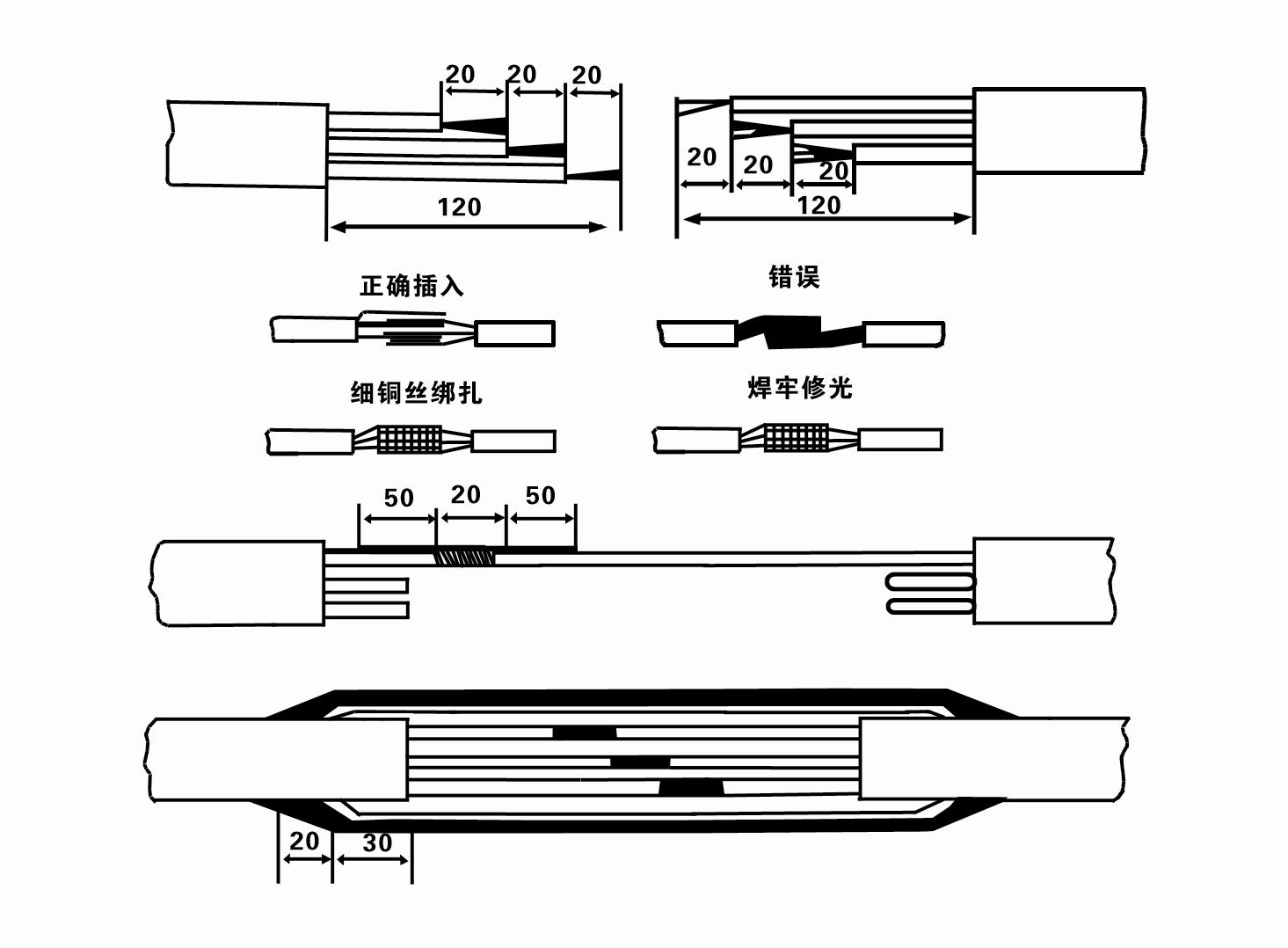
8. Use a multimeter to check whether the three-phase wires are connected and whether the DC resistance is approximately balanced.
9. Check whether the circuit and transformer capacity are overloaded, and then connect the overload protection switch or starting equipment. See Table 2 for specific models, and thenPour a bucket of water into the water pump from the water pump outlet to lubricate the rubber bearings in the pump, and then place the submersible electric pump upright and steady.Start (no more than one second) and check whether the steering direction is consistent with the steering sign. If not, swap any two connectors of the three-phase cable.Then install the filter and prepare to go down the well. If used in special occasions (such as ditches, ditches, rivers, ponds, ponds, etc.), the electric pump must be reliably grounded.
(2)Installation equipment and tools:
1. One pair of lifting chains for more than two tons.
2. A tripod with a vertical height of no less than four meters.
3. Two hanging ropes (wire ropes) that can bear a weight of more than one ton (can bear the weight of a complete set of water pumps).
4. Install two pairs of clamps (splints).
5. Wrenches, hammers, screwdrivers, electrical tools and instruments, etc.
(3)Electric pump installation:
1. The installation diagram of the submersible electric pump is shown in Figure 2. The specific installation dimensions are shown in Table 3 "List of Installation Dimensions of the Submersible Electric Pump".
2. Submersible electric pumps with a head less than 30 meters can be hoisted directly into the well using hoses and wire ropes or other hemp ropes that can bear the full weight of the entire machine, water pipes, and water in the pipes.
3. Pumps with a head of more than 30 meters use steel pipes, and the installation sequence is as follows:
①Use a clamp to clamp the upper end of the water pump part (the motor and water pump have been connected at this time), lift it with a hanging chain, and slowly tie it into the well untilPut the clamp on the wellhead and remove the hanging chain.
② Use another pair of clamps to clamp a pipe, lift it with a hanging chain 15 cm away from the flange, and lower it slowly. Between pipe flange and pump flangePut the rubber pad in place and tighten the pipe and pump evenly with bolts, nuts and spring washers.
③ Lift the submersible pump slightly, remove the clamp on the upper end of the water pump, tie the cable firmly to the water pipe with a plastic tape, and slowly tie it down until The clamp is placed at the wellhead.
④Use the same method to tie all water pipes into the well.
⑤After the lead-out cable is connected to the control switch, it is connected to the three-phase power supply.
(4)Things to note during installation:
1. If a jamming phenomenon is found during the pumping process, turn or pull the water pipe to overcome the jamming point. If various measures still do not work, pleaseDo not force the pump down to avoid damage to the submersible electric pump and the well.
2. During installation, a rubber pad should be placed at the flange of each pipe and tightened evenly.
3. When the water pump is lowered into the well, it should be placed in the middle of the well pipe to prevent the pump from running against the well wall for a long time, causing the pump to vibrate and the motor to sweep and burn.
4. Determine the depth of the water pump to the bottom of the well according to the flowing sand and silt conditions of the well. Do not bury the pump in the mud. The distance from the water pump to the bottom of the well is generally not less than 3 meters (see Figure 2).
5. The water entry depth of the water pump should be no less than 1-1.5 meters from the dynamic water level to the water inlet node (see Figure 2). Otherwise, the water pump bearings may be easily damaged.
6. The lift of the water pump cannot be too low. Otherwise, a gate valve needs to be installed on the wellhead water pipeline to control the pump flow at the rated flow point to prevent the motor from being overloaded and burned out due to large flow rates.
7. When the water pump is running, the water output should be continuous and even, the current should be stable (under rated working conditions, generally no more than 10% of the rated current), and there should be no vibration or noise. If there is any abnormality, the machine should be stopped to find out the cause and eliminate it.
8. When installing, pay attention to the setting of the motor grounding wire (see Figure 2). When the water pipe is a steel pipe, lead it from the wellhead clamp; when the water pipe is a plastic pipe, lead it from the grounding mark of the electric pump.
- 1.After the submersible pump is installed, check the insulation resistance and three-phase conduction from the switch again, check whether the instrument and the connection of the start equipment are wrong, if there is no problem, the trial machine can be started, and observe whether the indicator readings of the instrument exceed the rated voltage and current specified on the nameplate after the start, and observe whether the pump has noise and vibration phenomenon, and put into operation if everything is normal.
- 2.After the first operation of the pump for four hours, the motor should be shut down to test the thermal insulation resistance quickly, and its value should not be less than 0.5 megaohm.
- 3.After the pump is shut down, it should be started after five minutes to prevent the water column in the pipe from being completely reflowed and causing excessive motor current and burnout.
- 4.After the pump is put into normal operation, in order to prolong its service life, it is necessary to check whether the supply voltage, working current and insulation resistance are normal regularly. If the following conditions are found, the pump should be shut down immediately to troubleshoot.
- - In the rated condition, the current exceeds 20%.
- - The dynamic water level drops to the water inlet section, causing intermittent water.
- - The submersible pump has severe vibration or noise.
- - The supply voltage is lower than 340 volts.
- 5.A fuse is burned out.
- 6.The water supply pipe is damaged.
- 7.The motor's thermal insulation resistance is lower than 0.5 megaohm.
- Unit disassembly:
- 1.Untie the cable tie, remove the pipeline part, and remove the wire plate.
- 2.screw down the water bolt, put the water in the motor chamber.
- 3.remove the filter, loose the fixed screw on the coupling to fix the motor shaft.
- 4.screw down the bolt connecting the water inlet section with the motor, and separate the pump from the motor (pay attention to the unit cushion when separating, to prevent the bending of the pump shaft)
- 5.the disassembly sequence of the pump is: (see figure 1) water inlet section, impeller, diversion shell, impeller...... check valve body, when removing the impeller, use special tools to loosen the conical sleeve of the fixed impeller first, and avoid bending and bruising the pump shaft in the process of disassembly.
- 6.the disassembly process of the motor is: (see figure 1) place the motor on the platform, and remove the nuts, base, shaft head locking nut, thrust plate, key, lower guide bearing seat and double head bolt from the bottom of the motor in turn, and then take out the rotor (pay attention not to damage the wire package) and finally remove the connecting section and upper guide bearing seat.
- 7.unit assembly: before assembly, the rust and dirt of the parts should be cleaned, and the mating surface and fasteners coated with sealant, and then assembled in the opposite order of disassembly (the motor shaft moves up and down after assembly for about one millimeter), after assembly, the coupling should be flexible, and then the filter screen test machine. Submersible pumps shall be taken out of the well for dismantling and maintenance according to Article 5 after a year of operation, or less than a year of operation but two years of diving time, and the worn parts shall be replaced.
1, put out the water in the motor cavity (especially in winter to prevent the motor from freezing), and tie the cable well.
2, store in an indoor room without corrosive substances and gases, with a temperature below 40 °C.
3, long-term use should pay attention to the rust prevention of submersible pumps.
- Impeller
- Shaft sleeve
- Rubber shaft sleeve
-
Sealing ring
01 Deep well water intake
02 High-rise water supply
03 mountain water supply
04 tower water
05 Agricultural irrigation
06 garden irrigation
07 river water intake
08 domestic water


