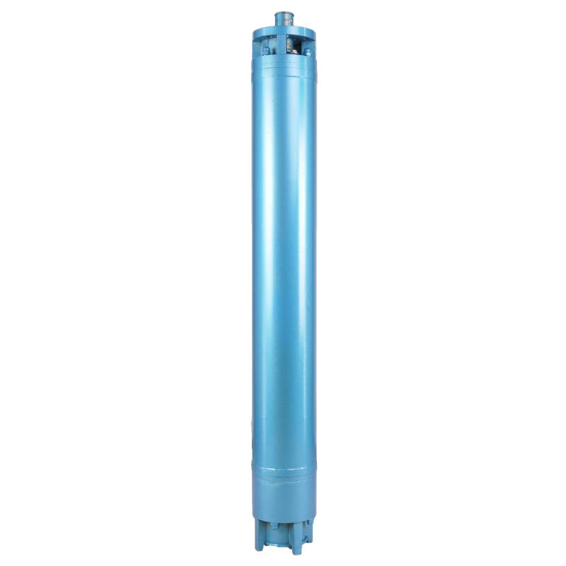
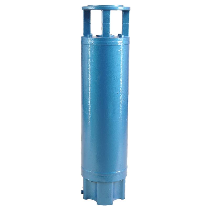
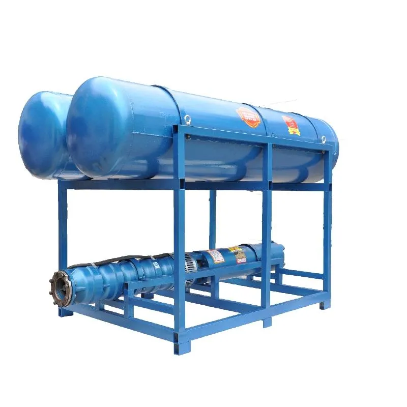
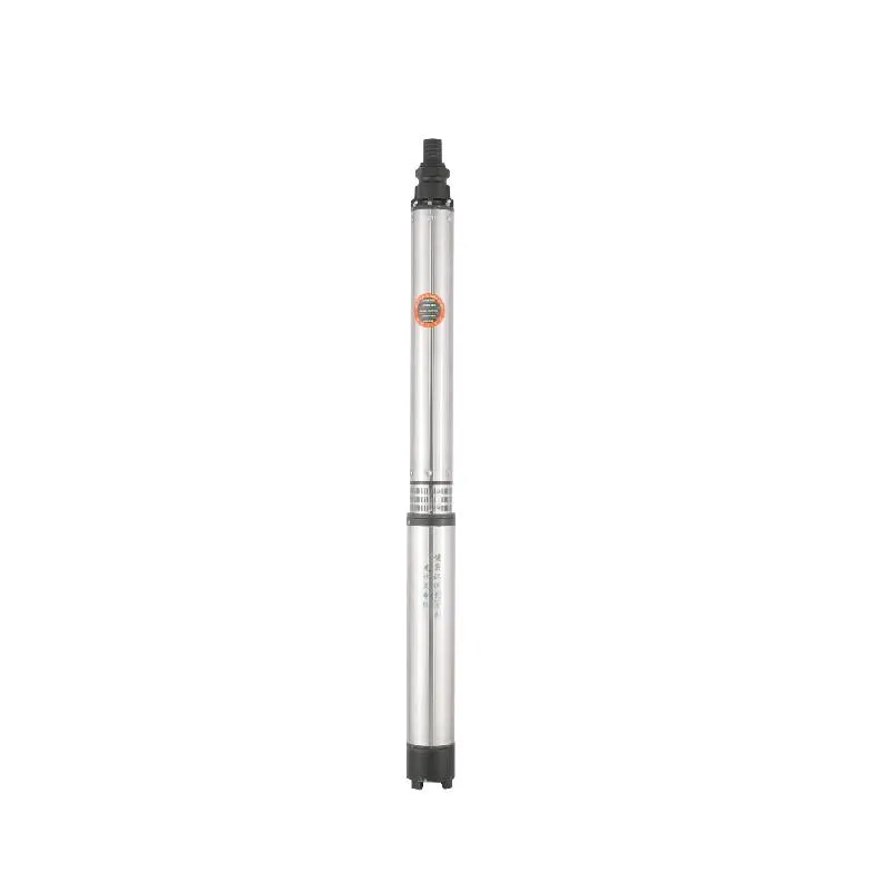
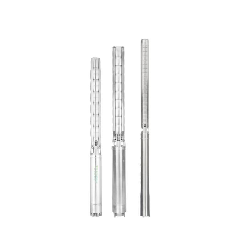
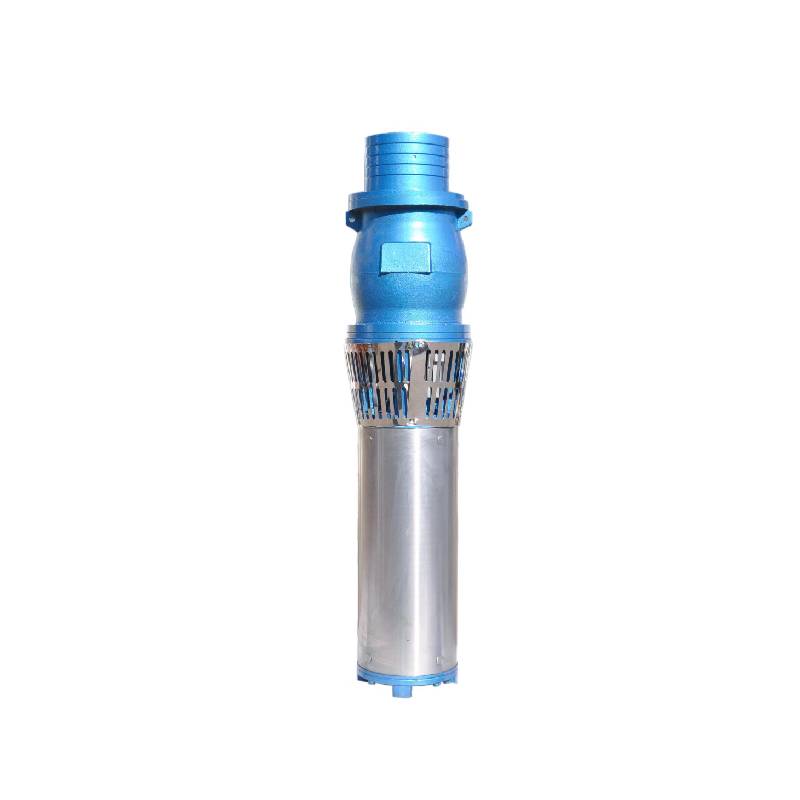
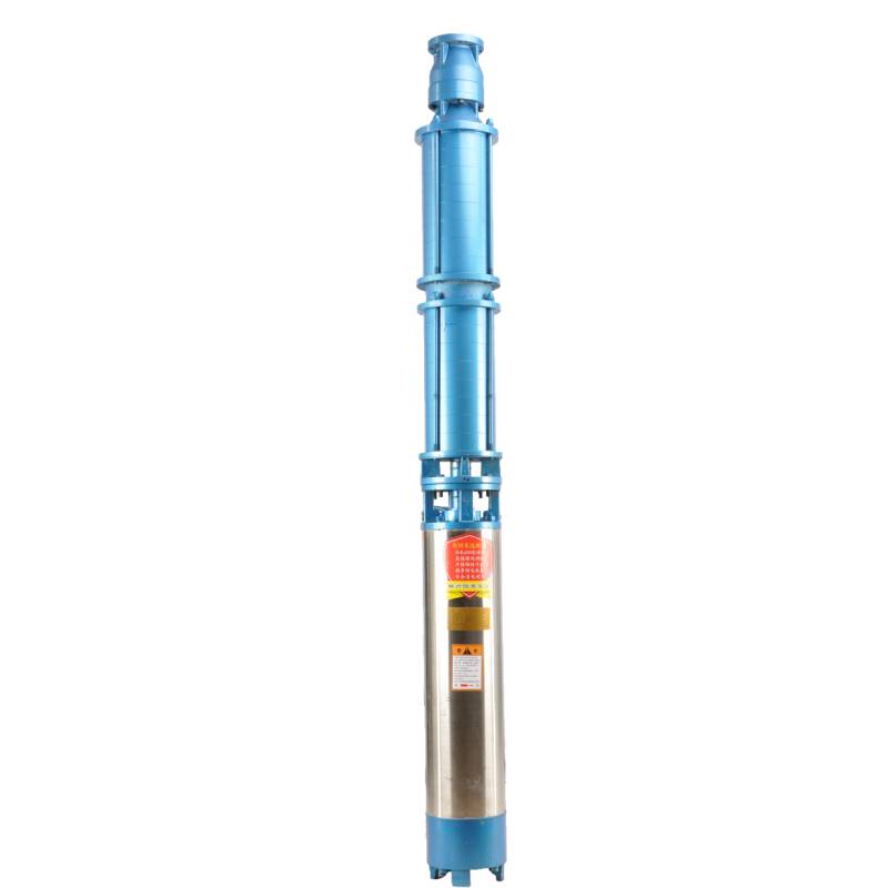
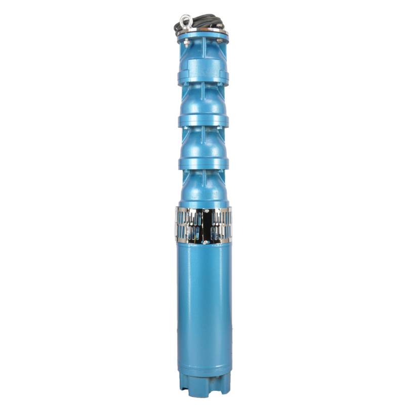
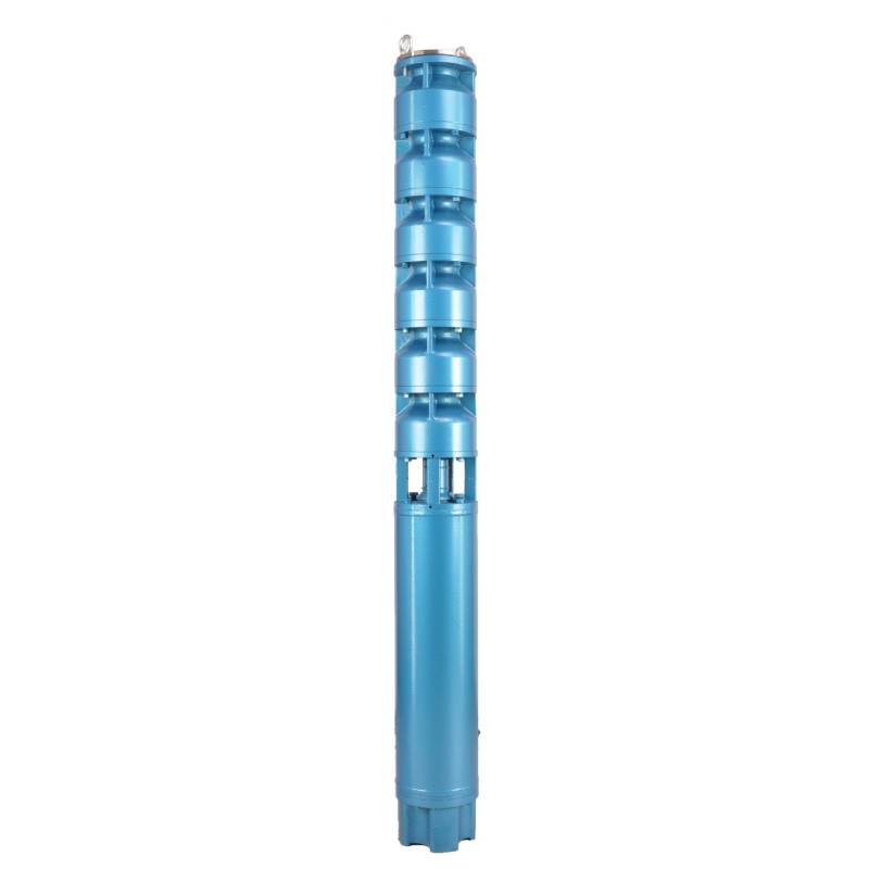
This product is designed for underground hot water mining and is suitable for water temperatures below 100°C. It has high temperature resistance, corrosion resistance and aging resistance. This product is very suitable for use in underground hot water mining environments, which can effectively deal with high temperatures and corrosion of various chemical substances, while having good aging resistance, ensuring stable operation of equipment for a long time. Whether it is needed to be used in harsh mining environments or in the face of high water temperatures, this product can provide reliable protection, ensuring continuous operation and efficient work of equipment.
Product introduction: we recommend this product is equipped with three-phase AC 380V (tolerance + / - 1%), 50HZ (tolerance + / - 1%) power supply. Water quality requirements are strict, the water temperature shall not be higher than 20 °C, the content of solid impurities (mass ratio) shall not be greater than 0.01%; PH value (pH) between 6.5-8.5; hydrogen sulfide content shall not be greater than 1.5mg/L; chloride ion content shall not exceed 400mg/L. The product is equipped with a closed or water-cooled wet structure motor. Before use, the inner cavity of the submersible motor shall be filled with clean water to prevent empty. Then tighten the water injection and air exhaust screws, otherwise it is prohibited to use. The submersible pump must be completely immersed in water to operate, the penetration depth shall not exceed 70 meters, and the distance between the bottom of the submersible pump and the bottom of the well shall not be less than 3 meters. The inflow of well water shall meet the water output and continuous operation requirements of the submersible pump, and the water output of the pump shall be controlled between 0.7 and 1.2 times the rated flow. The well must be vertical, and the submersible pump can not be used horizontally or dumped, but only vertically. The submersible pump must be equipped with cables as required, and is equipped with external overload protection device. It is prohibited to test the pump without water and no load.
| Model | Llif (m3/h) | Pen (m) |
Cyflymder cylchdroi (newid/pwynt) |
Pwmp dŵr(%) | Allfa diamedr (mm) |
Yn berthnasol yn dda diamedr (mm) |
Wedi'i raddio power(KW) |
Wedi'i raddio foltedd(V) |
Wedi'i raddio cerrynt (A) |
Effeithlonrwydd modur (%) | power factorcosφ | Uned Maint mwyaf rheiddiol (mm) |
|||||||||
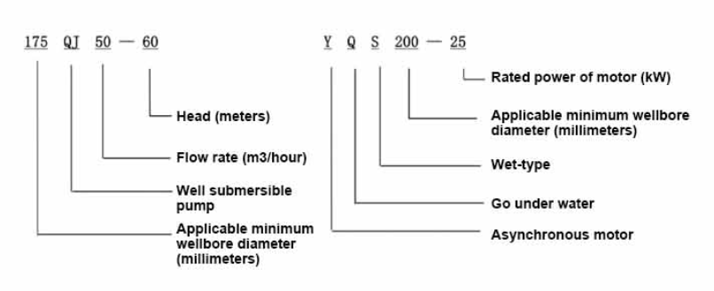
| 175QJ10-42 | 10 | 42 | 2850 | 53 | 50 | 175uchod | 3 | 380 | 7.8 | 74.0 | 0.79 | 168 | |||||||||
| 175QJ10-56 | 56 | 4 | 10.1 | 76.0 | 0.79 | ||||||||||||||||
| 175QJ10-70 | 70 | 4 | 10.1 | 76.0 | 0.79 | ||||||||||||||||
| 175QJ10-84 | 84 | 5.5 | 13.6 | 77.0 | 0.8 | ||||||||||||||||
| 175QJ10-112 | 112 | 7.5 | 18.4 | 77.5 | 0.8 | ||||||||||||||||
| 175QJ10-126 | 126 | 7.5 | 18.4 | 77.5 | 0.8 | ||||||||||||||||
| 175QJ10-140 | 140 | 9.2 | 22.1 | 78.0 | 0.81 | ||||||||||||||||
| 175QJ15-42 | 15 | 42 | 2850 | 58 | 50 | 175uchod | 4 | 380 | 10.1 | 76.0 | 0.79 | 168 | |||||||||
| 175QJ15-55 | 55 | 5.5 | 13.6 | 77.0 | 0.8 | ||||||||||||||||
| 175QJ15-65 | 65 | 5.5 | 13.6 | 77.0 | 0.8 | ||||||||||||||||
| 175QJ15-85 | 85 | 7.5 | 18.4 | 77.5 | 0.8 | ||||||||||||||||
| 175QJ15-112 | 112 | 9.2 | 22.1 | 78.0 | 0.81 | ||||||||||||||||
| 175QJ20-26 | 20 | 26 | 2850 | 64 | 50 | 175uchod | 3 | 380 | 7.8 | 74.0 | 0.79 | 168 | |||||||||
| 175QJ20-39 | 39 | 4 | 10.1 | 76.0 | 0.79 | ||||||||||||||||
| 175QJ20-52 | 52 | 5.5 | 13.6 | 77.0 | 0.8 | ||||||||||||||||
| 175QJ20-78 | 78 | 7.5 | 18.4 | 77.5 | 0.8 | ||||||||||||||||
| 175QJ20-91 | 91 | 9.2 | 22.1 | 78.0 | 0.81 | ||||||||||||||||
| 175QJ20-104 | 104 | 11 | 26.1 | 79.0 | 0.81 | ||||||||||||||||
| 175QJ20-130 | 130 | 13 | 30.1 | 80.0 | 0.82 | ||||||||||||||||
| 175QJ20-156 | 156 | 15 | 34.7 | 80.0 | 0.82 | ||||||||||||||||
| 175QJ20-182 | 187 | 18.5 | 42.6 | 80.5 | 0.82 | ||||||||||||||||
| 175QJ20-208 | 208 | 22 | 49.7 | 81.0 | 0.83 | ||||||||||||||||
| 175QJ20-247 | 247 | 25 | 56.5 | 81.0 | 0.83 | ||||||||||||||||
| 175QJ20-273 | 273 | 30 | 66.6 | 81.5 | 0.84 | ||||||||||||||||
| 175QJ20-299 | 299 | 30 | 66.6 | 81.5 | 0.84 | ||||||||||||||||
| 175QJ20-325 | 325 | 32 | 71.0 | 81.5 | 0.84 | ||||||||||||||||
| 175QJ20-364 | 364 | 37 | 82.1 | 81.5 | 0.84 | ||||||||||||||||
| 175QJ25-26 | 25 | 26 | 2850 | 66 | 65 | 175uchod | 3 | 380 | 7.8 | 74.0 | 0.79 | 168 | |||||||||
| 175QJ25-39 | 39 | 5.5 | 13.6 | 77.0 | 0.8 | ||||||||||||||||
| 175QJ25-65 | 25 | 65 | 2850 | 66 | 65 | 175uchod | 7.5 | 380 | 18.4 | 77.5 | 0.8 | 168 | |||||||||
| 175QJ25-78 | 78 | 9.2 | 22.1 | 78.0 | 0.81 | ||||||||||||||||
| 175QJ25-91 | 91 | 11 | 26.1 | 79.0 | 0.81 | ||||||||||||||||
| 175QJ25-104 | 104 | 13 | 30.1 | 80.0 | 0.82 | ||||||||||||||||
| 175QJ25-130 | 130 | 15 | 34.7 | 80.0 | 0.82 | ||||||||||||||||
| 175QJ25-156 | 156 | 18.5 | 42.6 | 80.5 | 0.82 | ||||||||||||||||
| 175QJ25-182 | 182 | 22 | 49.7 | 81.0 | 0.83 | ||||||||||||||||
| 175QJ25-208 | 208 | 25 | 56.5 | 81.0 | 0.83 | ||||||||||||||||
| 175QJ25-221 | 221 | 30 | 66.6 | 81.5 | 0.84 | ||||||||||||||||
| 175QJ25-247 | 247 | 30 | 66.6 | 81.5 | 0.84 | ||||||||||||||||
| 175QJ25-260 | 260 | 32 | 71.0 | 81.5 | 0.84 | ||||||||||||||||
| 175QJ25-299 | 299 | 37 | 82.1 | 81.5 | 0.84 | ||||||||||||||||
| 175QJ30-30 | 30 | 30 | 2850 | 67 | 80 | 175uchod | 4 | 380 | 10.1 | 76.0 | 0.79 | 168 | |||||||||
| 175QJ30-40 | 40 | 5.5 | 13.6 | 77.0 | 0.8 | ||||||||||||||||
| 175QJ32-24 | 32 | 24 | 2850 | 67 | 80 | 175uchod | 4 | 380 | 10.1 | 76.0 | 0.79 | 168 | |||||||||
| 175QJ32-36 | 36 | 5.5 | 13.6 | 77.0 | 0.8 | ||||||||||||||||
| 175QJ32-48 | 48 | 7.5 | 18.4 | 77.5 | 0.8 | ||||||||||||||||
| 175QJ32-60 | 60 | 9.2 | 22.1 | 78.0 | 0.81 | ||||||||||||||||
| 175QJ32-72 | 72 | 11 | 26.1 | 79.0 | 0.81 | ||||||||||||||||
| 175QJ32-84 | 84 | 13 | 30.1 | 80.0 | 0.82 | ||||||||||||||||
| 175QJ32-96 | 96 | 15 | 34.7 | 80.0 | 0.82 | ||||||||||||||||
| 175QJ32-120 | 120 | 18.5 | 42.6 | 80.5 | 0.82 | ||||||||||||||||
| 175QJ32-144 | 144 | 22 | 49.7 | 81.0 | 0.83 | ||||||||||||||||
| 175QJ32-168 | 168 | 25 | 56.5 | 81.0 | 0.83 | ||||||||||||||||
| 175QJ32-180 | 180 | 30 | 66.6 | 81.5 | 0.84 | ||||||||||||||||
| 175QJ32-192 | 192 | 30 | 66.6 | 81.5 | 0.84 | ||||||||||||||||
| 175QJ32-204 | 204 | 32 | 71.0 | 81.5 | 0.84 | ||||||||||||||||
| 175QJ32-240 | 240 | 37 | 82.1 | 81.5 | 0.84 | ||||||||||||||||
| 175QJ35-60 | 35 | 60 | 2850 | 67 | 80 | 175uchod | 10 | 380 | 25.0 | 78.0 | 0.78 | 168 | |||||||||
| 175QJ35-75 | 75 | 13 | 30.1 | 80.0 | 0.82 | ||||||||||||||||
| 175QJ35-100 | 100 | 17 | 40.9 | 80.0 | 0.79 | ||||||||||||||||
| 175QJ40-24 | 40 | 24 | 2850 | 70 | 80 | 175uchod | 5.5 | 380 | 13.6 | 77.0 | 0.8 | 168 | |||||||||
| 175QJ40-30 | 30 | 5.5 | 13.6 | 77.0 | 0.8 | ||||||||||||||||
| 175QJ40-36 | 36 | 7.5 | 18.4 | 77.5 | 0.8 | ||||||||||||||||
| 175QJ40-48 | 48 | 9.2 | 22.1 | 78.0 | 0.81 | ||||||||||||||||
| 175QJ40-60 | 60 | 11 | 26.1 | 79.0 | 0.81 | ||||||||||||||||
| 175QJ40-72 | 72 | 13 | 30.1 | 80.0 | 0.82 | ||||||||||||||||
| 175QJ40-84 | 84 | 15 | 34.7 | 80.0 | 0.82 | ||||||||||||||||
| 175QJ40-96 | 96 | 18.5 | 42.6 | 80.5 | 0.82 | ||||||||||||||||
| 175QJ40-120 | 120 | 22 | 49.7 | 81.0 | 0.83 | ||||||||||||||||
| 175QJ40-132 | 132 | 25 | 56.5 | 81.0 | 0.83 | ||||||||||||||||
| 175QJ40-144 | 144 | 30 | 66.6 | 81.5 | 0.84 | ||||||||||||||||
| 175QJ40-156 | 156 | 30 | 66.6 | 81.5 | 0.84 | ||||||||||||||||
| 175QJ40-168 | 168 | 32 | 71.0 | 81.5 | 0.84 | ||||||||||||||||
| 175QJ40-192 | 192 | 37 | 82.1 | 81.5 | 0.84 | ||||||||||||||||
| 175QJ50-24 | 50 | 24 | 2850 | 72 | 80 | 175uchod | 5.5 | 380 | 13.6 | 77.0 | 0.8 | 168 | |||||||||
| 175QJ50-36 | 36 | 9.2 | 22.1 | 78.0 | 0.81 | ||||||||||||||||
| 175QJ50-48 | 48 | 11 | 26.1 | 79.0 | 0.81 | ||||||||||||||||
| 175QJ50-60 | 60 | 13 | 30.1 | 80.0 | 0.82 | ||||||||||||||||
| 175QJ50-70 | 70 | 17 | 40.9 | 80.0 | 0.79 | ||||||||||||||||
| 175QJ50-84 | 84 | 18.5 | 42.6 | 80.5 | 0.82 | ||||||||||||||||
| 175QJ50-96 | 96 | 22 | 49.7 | 81.0 | 0.83 | ||||||||||||||||
| 175QJ50-108 | 108 | 25 | 56.5 | 81.0 | 0.83 | ||||||||||||||||
| 175QJ50-120 | 120 | 30 | 66.6 | 81.5 | 0.84 | ||||||||||||||||
| 175QJ50-132 | 132 | 30 | 66.6 | 81.5 | 0.84 | ||||||||||||||||
| 175QJ50-144 | 144 | 32 | 71.0 | 81.5 | 0.84 | ||||||||||||||||
| 175QJ50-156 | 156 | 37 | 82.1 | 81.5 | 0.84 | ||||||||||||||||
| 175QJ63-22 | 63 | 22 | 2850 | 72 | 80 | 175uchod | 7.5 | 380 | 18.4 | 77.5 | 0.8 | 168 | |||||||||
| 175QJ63-44 | 44 | 13 | 30.1 | 80.0 | 0.82 | ||||||||||||||||
| 175QJ63-55 | 55 | 15 | 34.7 | 80.0 | 0.82 | ||||||||||||||||
| 175QJ63-66 | 66 | 18.5 | 42.6 | 80.5 | 0.82 | ||||||||||||||||
| 175QJ63-77 | 77 | 22 | 49.7 | 81.0 | 0.83 | ||||||||||||||||
| 175QJ63-88 | 88 | 25 | 56.5 | 81.0 | 0.83 | ||||||||||||||||
| 175QJ63-99 | 63 | 99 | 2850 | 72 | 80 | 175uchod | 30 | 380 | 66.6 | 81.5 | 0.84 | 168 | |||||||||
| 175QJ63-110 | 110 | 32 | 71.0 | 81.5 | 0.84 | ||||||||||||||||
| 175QJ63-132 | 132 | 37 | 82.1 | 81.5 | 0.84 | ||||||||||||||||
| 175QJ80-9 | 80 | 9 | 2850 | 73 | 100 | 175uchod | 4 | 380 | 10.1 | 76.0 | 0.79 | 168 | |||||||||
| 175QJ80-18 | 18 | 7.5 | 18.4 | 77.5 | 0.8 | ||||||||||||||||
| 175QJ80-27 | 27 | 11 | 26.1 | 79.0 | 0.81 | ||||||||||||||||
| 175QJ80-36 | 36 | 15 | 34.7 | 80.0 | 0.82 | ||||||||||||||||
| 175QJ80-45 | 45 | 18.5 | 42.6 | 80.5 | 0.82 | ||||||||||||||||
| 175QJ80-54 | 54 | 22 | 49.7 | 81.0 | 0.83 | ||||||||||||||||
| 175QJ80-63 | 63 | 25 | 56.5 | 81.0 | 0.83 | ||||||||||||||||
| 175QJ80-72 | 72 | 25 | 56.5 | 81.0 | 0.83 | ||||||||||||||||
| 175QJ80-81 | 81 | 30 | 66.6 | 81.5 | 0.84 | ||||||||||||||||
| 175QJ80-90 | 90 | 32 | 71.0 | 81.5 | 0.84 | ||||||||||||||||
| 175QJ80-98 | 98 | 37 | 82.1 | 81.5 | 0.84 | ||||||||||||||||
1, well submersible pump for clean water pump, prohibit the new well, pumping sediment and muddy water,
2, well water pump voltage grade of 380/50HZ, the use of other voltage grades of submersible motors need to be customized. The underground cable must use waterproof cable, must be equipped with starting equipment, such as distribution box, start not ready should have commonly used motor comprehensive protection function, such as short circuit overload protection, phase protection, undervoltage protection, grounding protection, idling protection, in case of abnormal conditions, the protection device should be timely action trip.
3, the installation and use of the pump must be reliably grounded, prohibit the push and pull switch when the hands and feet are wet, the installation and maintenance of the pump must be cut off the power supply, the use of the pump place to set up "to prevent electric shock" obvious signs:
4, down the well or before installation, the motor cavity must be filled with distilled water or non-corrosive clean cold boiling water, tighten the / water bolt, the pump on the ground test run, must be to the pump chamber water lubrication rubber bearings, instant start not more than a second, see whether the steering is the same as the steering instructions. When the pump is upright, pay attention to safety, prevent overturning injury.
5, yn llym yn unol â darpariaethau'r lifft pwmp, ystod llif y defnydd, i atal llif isel neu rym pwmpio lifft uchel, y dwyn byrdwn a rhannau eraill o'r gwisgo, y gorlwytho modur llosgi
6, after the pump down the well, the measurement of the motor to the ground insulation resistance should not be less than 100M, after the start to observe the voltage and current, check the motor winding insulation, whether in line with the requirements; pump storage location temperature if less than freezing point, should be dry the motor cavity water, prevent the motor cavity water ice damage caused by low temperature.
Cyflwyniad byr o'r strwythur: mae rhan pwmp yn cynnwys siafft pwmp yn bennaf, impeller, cragen dargyfeirio, dwyn rwber, corff falf gwirio (rhannau dewisol) a rhan cydrannau eraill. , sedd dwyn canllaw is, stator, rotor, sedd dwyn canllaw uchaf, cylch tywod, adran fewnfa dŵr, cebl a chydrannau eraill.
Mae prif nodweddion y cynnyrch yn cynnwys:
1, Mae'r modur yn fodur asyncronig tri cham tanddwr gwlyb llawn dŵr, mae'r ceudod modur yn llawn dŵr glân, a ddefnyddir i oeri'r modur ac iro'r dwyn, defnyddir y ffilm sy'n rheoleiddio pwysau ar waelod y modur i addasu gwahaniaeth pwysedd ehangu a chrebachu y dŵr y tu mewn i'r corff a achosir gan newid cynnydd tymheredd y modur.
2, Er mwyn atal y tywod yn y dŵr ffynnon rhag mynd i mewn i'r modur, mae dwy sêl olew ar ben uchaf y siafft modur, ac mae cylch tywod wedi'i osod i ffurfio strwythur atal tywod.
3, Er mwyn atal y siafft pwmp rhag rhedeg i fyny wrth gychwyn, mae'r siafft pwmp a'r siafft modur wedi'u cysylltu gan gyplu, a gosodir dwyn byrdwn uchaf ar ran isaf y modur.
4, Mae iro'r modur a'r dwyn pwmp yn iro dŵr.
5, Mae'r weindio stator modur wedi'i wneud o wifren dirwyn modur tanddwr o ansawdd uchel, gyda pherfformiad inswleiddio uchel.
6, Mae'r pwmp wedi'i ddylunio gan gyfrifiadur CAD, gyda strwythur syml a pherfformiad technegol da.

(1) Paratoi cyn gosod:
1. Gwiriwch a yw'r pwmp tanddwr yn bodloni'r amodau defnydd a'r cwmpas a nodir yn y llawlyfr.
2. Gan ddefnyddio gwrthrych trwm gyda diamedr sy'n hafal i diamedr allanol uchaf y pwmp tanddwr, mesurwch a all diamedr mewnol y ffynnon ffitio'r pwmp tanddwr, a mesur a yw dyfnder y ffynnon yn bodloni'r gofynion gosod.
3. Gwiriwch a yw tyllu'r ffynnon yn lân ac a yw dŵr y ffynnon yn gymylog. Peidiwch byth â defnyddio pwmp trydan tanddwr i olchi mwd y pwmp welor a dŵr tywod er mwyn osgoi niwed cynamserol i'r pwmp trydan tanddwr.
4. Gwiriwch a yw lleoliad y clamp gosod welhead yn addas ac a all wrthsefyll ansawdd yr uned gyfan
5. Gwiriwch a yw'r cydrannau pwmp tanddwr wedi'u cwblhau a'u gosod yn iawn yn ôl y diagram cydosod yn y llawlyfr Tynnwch y sgrin hidlo a chylchdroi'r cyplydd i weld a yw'n cylchdroi yn hyblyg
6. Dadsgriwiwch y sgriw dŵr a llenwi'r ceudod modur â dŵr glân nad yw'n cyrydol (noder. gwnewch yn siŵr ei ffiltro), yna tynhau'r sgriw dŵr. Ar ôl 12 awr o chwistrelliad dŵr, ni ddylai ymwrthedd inswleiddio'r modur fod yn llai na 150M Q wrth ei fesur gyda bwrdd ysgwyd 500V.
7. Cable joint, cut off a 120mm rubber sleeve from one end of the outgoing cable and the matching cable with an electrician's knifethen stagger the length of the three core wires in a stepped shape, peel off a 20mm copper core, scrape of the oxide layer on theoutside of the copper wire with a knife or sand cloth, and insert the two connected wire ends in palirs.After tying the layer tightly with fine copper wire, solder it thoroughly and firmly, and sand of any. burrs on the surface. Then, forthe three joints, use polyvester insulation tape to wrap them in a semi stacked manner for three lavers. Wrap the two ends of thewrapping layer tightywith nyion thread,and then use a semi stacked method to wrap the tape for three layers. Wrap the outellayer with high-pressure insulation tape for three layers. Finally, fold the threestrands together and repeatedly wrap them for fivelayers with high-pressure tape. Each layer must be tightly tied, and the interlayer joints must be tight and fimm to prevent water frompenetrating and damaging the insulation, After wrapping, soak in water at room temperature of 20 ’c for 12 hours, and measurethe insulation resistance with a shaking table, which should not be less than 100M Ω
Mae'r diagram proses gwifrau cebl ynghlwm fel a ganlyn: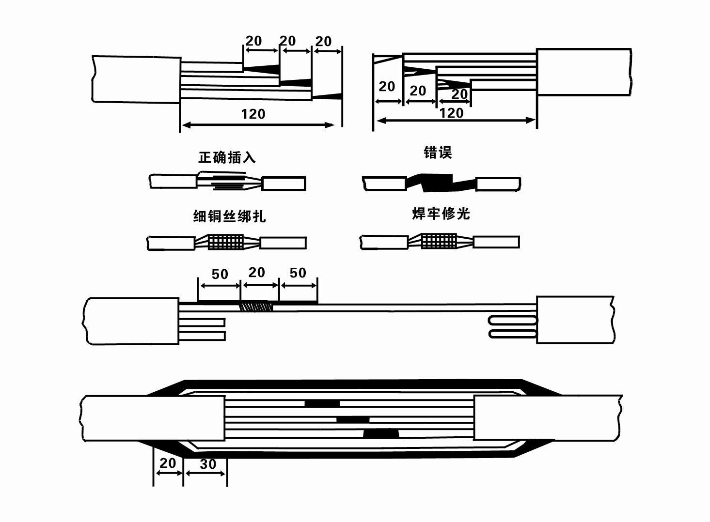
8. Defnyddiwch amlfesurydd i wirio a yw'r gwifrau tri cham wedi'u cysylltu ac a yw'r gwrthiant DC yn gyfartal yn fras.
9. Gwiriwch a yw'r cylched a chynhwysedd y trawsnewidydd yn cael eu gorlwytho, ac yna cysylltu'r switsh amddiffyn gorlwytho neu'r offer cychwyn. Gweler Tabl 2 am fodelau penodol, ac yna Arllwyswch bwced o ddŵr i'r pwmp dŵr o'r allfa pwmp dŵr i iro'r Bearings rwber yn y pwmp, ac yna gosodwch y pwmp trydan tanddwr yn unionsyth ac yn gyson.Start (dim mwy nag un eiliad) a gwirio a yw'r cyfeiriad llywio yn gyson â'r arwydd llywio. Os na, cyfnewidiwch unrhyw ddau gysylltydd o'r cebl tri cham. Yna gosodwch yr hidlydd a pharatowch i fynd i lawr y ffynnon. Os caiff ei ddefnyddio mewn achlysuron arbennig (fel ffosydd, ffosydd, afonydd, pyllau, pyllau, ac ati), rhaid i'r pwmp trydan gael ei seilio'n ddibynadwy.
(2) Offer ac offer gosod:
1. Un pâr o gadwyni codi am fwy na dwy dunnell.
2. Trybedd gydag uchder fertigol o ddim llai na phedwar metr.
3. Dau raff hongian (rhaffau gwifren) sy'n gallu dwyn pwysau o fwy nag un tunnell (gall ddwyn pwysau set gyflawn o bympiau dŵr).
4. Gosod dau bâr o clampiau (splints).
5. Wrenches, morthwylion, sgriwdreifers, offer trydanol ac offerynnau, ac ati.
(3) Gosod pwmp trydan:
1. Dangosir diagram gosod y pwmp trydan tanddwr yn Ffigur 2. Dangosir y dimensiynau gosod penodol yn Nhabl 3 "Rhestr o Dimensiynau Gosod y Pwmp Trydan Tanddwr".
2. Gellir codi pympiau trydan tanddwr â phen llai na 30 metr yn uniongyrchol i'r ffynnon gan ddefnyddio pibellau a rhaffau gwifren neu rhaffau cywarch eraill a all ddwyn pwysau llawn y peiriant cyfan, pibellau dŵr, a dŵr yn y pibellau.
3. Mae pympiau â phen o fwy na 30 metr yn defnyddio pibellau dur, ac mae'r dilyniant gosod fel a ganlyn:
①Defnyddiwch clamp i glampio pen uchaf rhan y pwmp dŵr (mae'r modur a'r pwmp dŵr wedi'u cysylltu ar hyn o bryd), codwch ef â chadwyn hongian, a'i glymu'n araf i mewn i'r ffynnon nes i chi roi'r clamp ar ben y ffynnon a thynnu'r cadwyn hongian.
② Defnyddiwch bâr arall o clampiau i glampio pibell, ei godi â chadwyn hongian 15 cm i ffwrdd o'r fflans, a'i ostwng yn araf. Rhwng fflans pibell a fflans pwmp Rhowch y pad rwber yn ei le a thynhau'r bibell a'r pwmp yn gyfartal â bolltau, cnau a wasieri gwanwyn.
③ Codwch y pwmp tanddwr ychydig, tynnwch y clamp ar ben uchaf y pwmp dŵr, clymwch y cebl yn gadarn i'r bibell ddŵr gyda thâp plastig, a'i glymu'n araf nes bod y clamp wedi'i osod ar ben y ffynnon.
④ Defnyddiwch yr un dull i glymu'r holl bibellau dŵr i'r ffynnon.
⑤ Ar ôl i'r cebl plwm-allan gael ei gysylltu â'r switsh rheoli, mae'n gysylltiedig â'r cyflenwad pŵer tri cham.
(4) Pethau i'w nodi yn ystod y gosodiad:
1. Os canfyddir ffenomen jamio yn ystod y broses bwmpio, trowch neu tynnwch y bibell ddŵr i oresgyn y pwynt jamio. Os nad yw mesurau amrywiol yn gweithio o hyd, peidiwch â gorfodi'r pwmp i lawr er mwyn osgoi difrod i'r pwmp trydan tanddwr a'r ffynnon.
2. Yn ystod y gosodiad, dylid gosod pad rwber ar fflans pob pibell a'i dynhau'n gyfartal.
3. Pan fydd y pwmp dŵr yn cael ei ostwng i'r ffynnon, dylid ei osod yng nghanol pibell y ffynnon i atal y pwmp rhag rhedeg yn erbyn wal y ffynnon am amser hir, gan achosi'r pwmp i ddirgrynu a'r modur i ysgubo a llosgi .
4. Darganfyddwch ddyfnder y pwmp dŵr i waelod y ffynnon yn ôl amodau tywod a silt y ffynnon sy'n llifo. Peidiwch â chladdu'r pwmp yn y mwd. Yn gyffredinol, nid yw'r pellter o'r pwmp dŵr i waelod y ffynnon yn llai na 3 metr (gweler Ffigur 2).
5. Ni ddylai dyfnder mynediad dŵr y pwmp dŵr fod yn llai na 1-1.5 metr o lefel y dŵr deinamig i'r nod mewnfa dŵr (gweler Ffigur 2). Fel arall, gall y Bearings pwmp dŵr gael eu niweidio'n hawdd.
6. Ni all lifft y pwmp dŵr fod yn rhy isel. Fel arall, mae angen gosod falf giât ar bibell ddŵr y ffynnon i reoli llif y pwmp ar y pwynt llif graddedig i atal y modur rhag cael ei orlwytho a'i losgi oherwydd cyfraddau llif mawr.
7. Pan fydd y pwmp dŵr yn rhedeg, dylai'r allbwn dŵr fod yn barhaus a hyd yn oed, dylai'r presennol fod yn sefydlog (o dan amodau gwaith graddedig, yn gyffredinol dim mwy na 10% o'r cerrynt graddedig), ac ni ddylai fod unrhyw ddirgryniad na sŵn. Os oes unrhyw annormaledd, dylid stopio'r peiriant i ddarganfod yr achos a'i ddileu.
8. Wrth osod, rhowch sylw i osodiad y wifren sylfaen modur (gweler Ffigur 2). Pan fydd y bibell ddŵr yn bibell ddur, ei harwain o'r clamp pen ffynnon; pan fydd y bibell ddŵr yn bibell blastig, ei arwain o farc sylfaen y pwmp trydan.
- 1.After the submersible pump is installed, check the insulation resistance and three-phase conduction from the switch again, check whether the instrument and the connection of the start equipment are wrong, if there is no problem, the trial machine can be started, and observe whether the indicator readings of the instrument exceed the rated voltage and current specified on the nameplate after the start, and observe whether the pump has noise and vibration phenomenon. If everything is normal, it can be put into operation.
- 2. After the first operation of the pump for four hours, the motor should be shut down to test the thermal insulation resistance quickly, and its value should not be less than 0.5 megaohm.
- 3. After the pump is shut down, it should be started after five minutes to prevent the water column in the pipe from burning due to excessive motor current.
- 4. After the pump is running normally, in order to prolong its service life, it is necessary to check whether the power supply voltage, running current and insulation resistance are normal on a regular basis.If the following conditions are found, the equipment should be shut down immediately to eliminate the fault:
- - Under the rated working conditions, the current exceeds 20%.
- - The dynamic water level drops to the inlet section, resulting in intermittent drainage.
- - The submersible pump vibrates violently or emits noisy sounds.
- - The power supply voltage is lower than 340 volts.
- - There is a phase blown out in the fuse.
- - The water pipe is damaged.
- - The thermal insulation resistance between the motor and the ground is less than 0.5 megaohm.
- 5. Disassembly device:
- - Untie the cable, take off the pipe part and remove the line protection plate.
- - Unscrew the drain screw and exclude all water in the motor chamber.
- - Take out the filter and loosen the fixing screw on the coupling fixed to the motor shaft.
- - Unscrew the bolt connecting the water inlet section and the motor, and separate the pump and the motor (pay attention to the level of the device to prevent the bending of the pump shaft when separating).
- - The disassembly sequence of the pump is as follows: (see Figure 1) water inlet section, impeller, shunt shell, impeller, check valve body. When removing the impeller, use special tools to loosen the cone sleeve fixed to the impeller. In the process of disassembly, avoid bending the pump shaft and damaging various parts.
- - The disassembly process of the motor is as follows: (see Figure 1) place the motor on the platform, and remove the nuts, base, shaft head lock nut, thrust plate, key, lower guide bearing. seat, and tie rod bolts from the bottom of the motor in order (see Figure 1), and then take out the rotor (be careful not to damage the wiring harness) and finally take out the connector and upper guide bearing seat.
- - Assembly unit: before assembly, all parts should be cleaned of rust and dirt, and smear sealant on all the surfaces and fasteners, and then assemble in the opposite order of disassembly (the movement of the motor shaft after assembly is about 1 mm). After assembly, the coupling should be flexible, and then wear the filter for machine test. Submersible pumps shall be taken out of the well for dismantling and maintenance according to Article 5 after a year of operation, or less than a year of operation but two years of diving time, and the worn parts shall be replaced.
1, rhowch y dŵr allan yn y ceudod modur (yn enwedig yn y gaeaf i atal y modur rhag rhewi), a chlymwch y cebl yn dda.
2, store in an indoor room without corrosive substances and gases, with a temperature below 40 °C.
3, dylai defnydd hirdymor roi sylw i atal rhwd pympiau tanddwr.
- Impeller
- Llawes siafft
- Llawes siafft rwber
-
Modrwy selio
01 Cymeriant dŵr ffynnon dwfn
02 Cyflenwad dŵr uchel
03 cyflenwad dŵr mynydd
04 twr dwr
05 Dyfrhau amaethyddol
06 dyfrhau gardd
07 cymeriant dŵr afon
08 dŵr domestig


