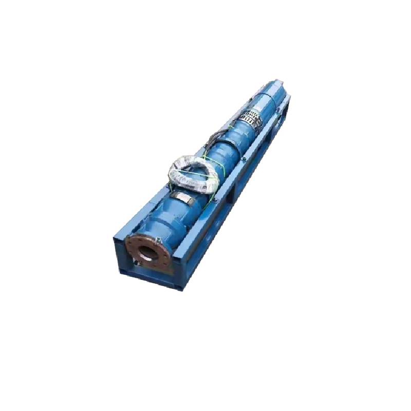
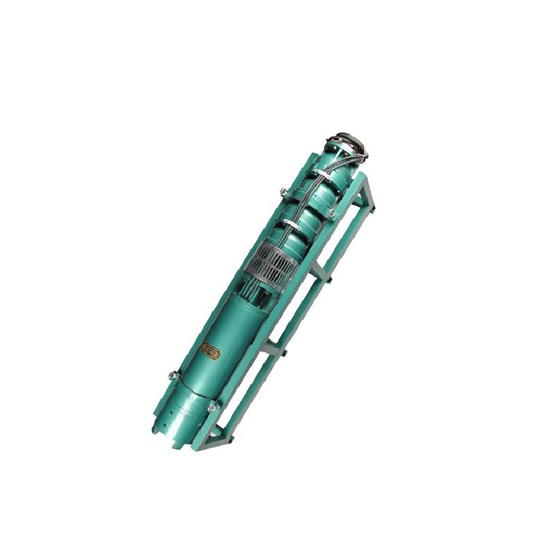
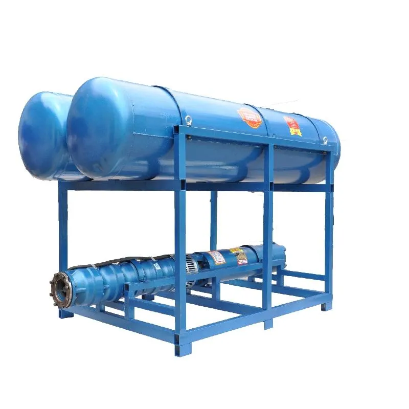
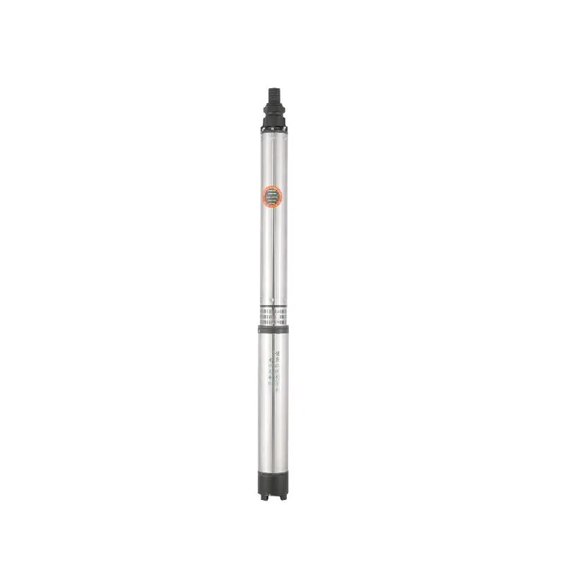
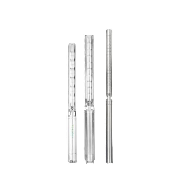
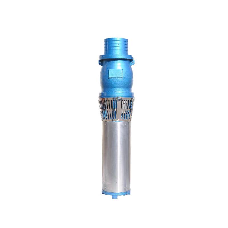
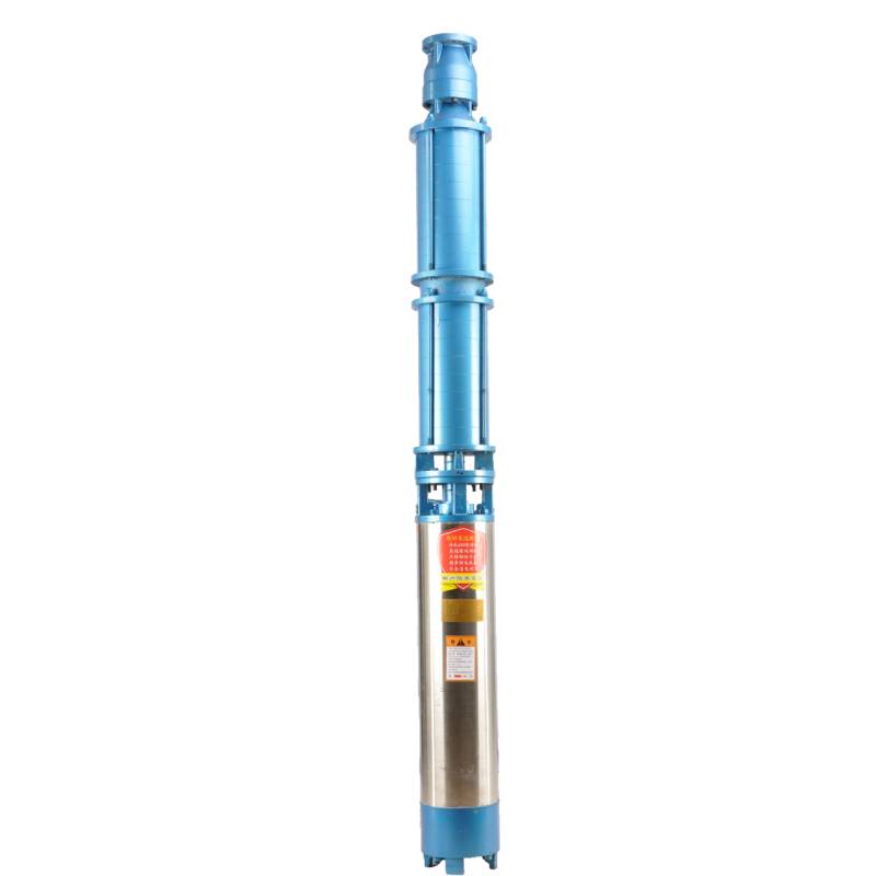
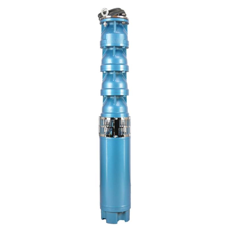
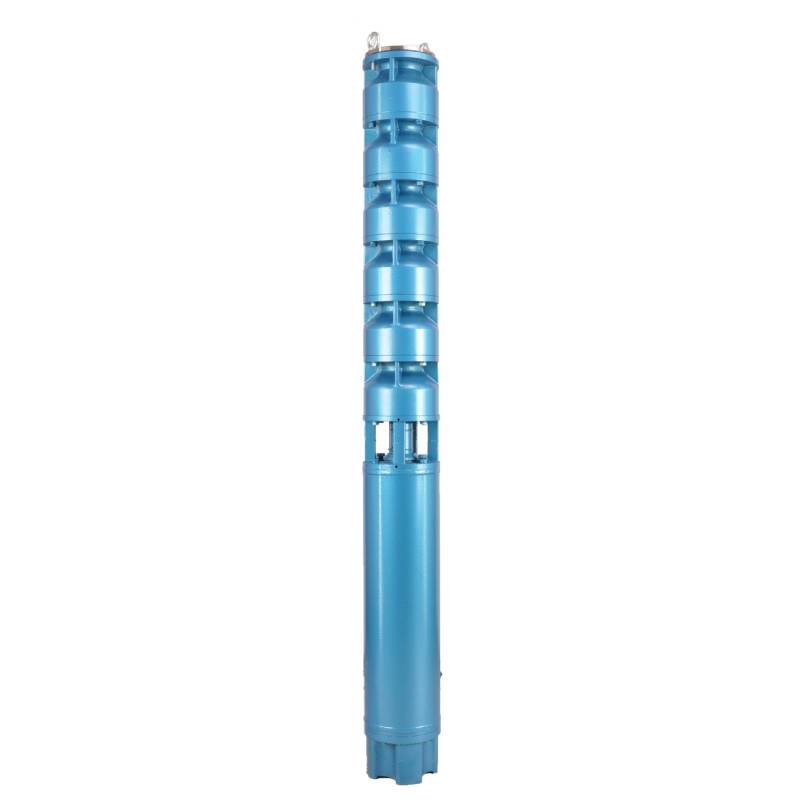
QJP series fountain pump is a special pump for fountain developed by our factory.The pump motor core is made of high quality cold rolled silicon steel, which makes the pump more efficient, good magnetic conductivity, and frequent start will not fever.Both ends of the motor rotor use water as lubricant alloy copper sleeve.Stainless steel sleeve instead of ball bearings, to avoid the problem of easy rust ball bearings and lack of oil wear and tear the motor.The most suitable for music fountain use, all models can be used.
This product is a three-phase AC 380V (tolerance + / - 5%), 50HZ (tolerance + / - 1%) power supply system. Applicable water quality conditions include water temperature not exceeding 20 °C, solid impurities content (mass ratio) is not greater than 0.01%, PH value (pH) is 6.5-8.5, hydrogen sulfide content is not greater than 1.5mg/L, chloride ion content is not greater than 400mg/L. The motor is a closed or water-filled wet structure. Before use, it must be filled with clean water to prevent false filling, and then tighten the water injection and exhaust bolts, otherwise it is not allowed to use. The submersible pump must be completely immersed in water, and the penetration depth shall not exceed 70m. The distance between the submersible pump base and the bottom of the well shall not be less than 3m. The well flow shall be able to meet the water output and continuous operation of the submersible pump. The water output of the submersible pump shall be controlled at 0.7-1.2 times of the rated flow. The well shall be vertical, and the submersible pump can not be used horizontally or upside down, but only vertically. The submersible pump shall be equipped with cables and external overload protection devices as required. The pump is strictly prohibited from no-load test without water.
| Modèle | Débit (m3/h) | Tête (m) |
Vitesse de rotation (changement/point) |
Pompe à eau(%) | Sortie diamètre (mm) |
Bien applicable diamètre (mm) |
Noté power(KW) |
Noté tension (V) |
Noté courant (A) |
Efficacité moteur (%) | power factorcosφ | Unité Taille maximale radiale (mm) |
|||||||||
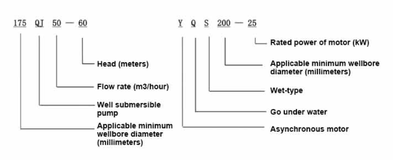
| 175QJ10-42 | 10 | 42 | 2850 | 53 | 50 | 175au-dessus de | 3 | 380 | 7.8 | 74.0 | 0.79 | 168 | |||||||||
| 175QJ10-56 | 56 | 4 | 10.1 | 76.0 | 0.79 | ||||||||||||||||
| 175QJ10-70 | 70 | 4 | 10.1 | 76.0 | 0.79 | ||||||||||||||||
| 175QJ10-84 | 84 | 5.5 | 13.6 | 77.0 | 0.8 | ||||||||||||||||
| 175QJ10-112 | 112 | 7.5 | 18.4 | 77.5 | 0.8 | ||||||||||||||||
| 175QJ10-126 | 126 | 7.5 | 18.4 | 77.5 | 0.8 | ||||||||||||||||
| 175QJ10-140 | 140 | 9.2 | 22.1 | 78.0 | 0.81 | ||||||||||||||||
| 175QJ15-42 | 15 | 42 | 2850 | 58 | 50 | 175au-dessus de | 4 | 380 | 10.1 | 76.0 | 0.79 | 168 | |||||||||
| 175QJ15-55 | 55 | 5.5 | 13.6 | 77.0 | 0.8 | ||||||||||||||||
| 175QJ15-65 | 65 | 5.5 | 13.6 | 77.0 | 0.8 | ||||||||||||||||
| 175QJ15-85 | 85 | 7.5 | 18.4 | 77.5 | 0.8 | ||||||||||||||||
| 175QJ15-112 | 112 | 9.2 | 22.1 | 78.0 | 0.81 | ||||||||||||||||
| 175QJ20-26 | 20 | 26 | 2850 | 64 | 50 | 175au-dessus de | 3 | 380 | 7.8 | 74.0 | 0.79 | 168 | |||||||||
| 175QJ20-39 | 39 | 4 | 10.1 | 76.0 | 0.79 | ||||||||||||||||
| 175QJ20-52 | 52 | 5.5 | 13.6 | 77.0 | 0.8 | ||||||||||||||||
| 175QJ20-78 | 78 | 7.5 | 18.4 | 77.5 | 0.8 | ||||||||||||||||
| 175QJ20-91 | 91 | 9.2 | 22.1 | 78.0 | 0.81 | ||||||||||||||||
| 175QJ20-104 | 104 | 11 | 26.1 | 79.0 | 0.81 | ||||||||||||||||
| 175QJ20-130 | 130 | 13 | 30.1 | 80.0 | 0.82 | ||||||||||||||||
| 175QJ20-156 | 156 | 15 | 34.7 | 80.0 | 0.82 | ||||||||||||||||
| 175QJ20-182 | 187 | 18.5 | 42.6 | 80.5 | 0.82 | ||||||||||||||||
| 175QJ20-208 | 208 | 22 | 49.7 | 81.0 | 0.83 | ||||||||||||||||
| 175QJ20-247 | 247 | 25 | 56.5 | 81.0 | 0.83 | ||||||||||||||||
| 175QJ20-273 | 273 | 30 | 66.6 | 81.5 | 0.84 | ||||||||||||||||
| 175QJ20-299 | 299 | 30 | 66.6 | 81.5 | 0.84 | ||||||||||||||||
| 175QJ20-325 | 325 | 32 | 71.0 | 81.5 | 0.84 | ||||||||||||||||
| 175QJ20-364 | 364 | 37 | 82.1 | 81.5 | 0.84 | ||||||||||||||||
| 175QJ25-26 | 25 | 26 | 2850 | 66 | 65 | 175au-dessus de | 3 | 380 | 7.8 | 74.0 | 0.79 | 168 | |||||||||
| 175QJ25-39 | 39 | 5.5 | 13.6 | 77.0 | 0.8 | ||||||||||||||||
| 175QJ25-65 | 25 | 65 | 2850 | 66 | 65 | 175au-dessus de | 7.5 | 380 | 18.4 | 77.5 | 0.8 | 168 | |||||||||
| 175QJ25-78 | 78 | 9.2 | 22.1 | 78.0 | 0.81 | ||||||||||||||||
| 175QJ25-91 | 91 | 11 | 26.1 | 79.0 | 0.81 | ||||||||||||||||
| 175QJ25-104 | 104 | 13 | 30.1 | 80.0 | 0.82 | ||||||||||||||||
| 175QJ25-130 | 130 | 15 | 34.7 | 80.0 | 0.82 | ||||||||||||||||
| 175QJ25-156 | 156 | 18.5 | 42.6 | 80.5 | 0.82 | ||||||||||||||||
| 175QJ25-182 | 182 | 22 | 49.7 | 81.0 | 0.83 | ||||||||||||||||
| 175QJ25-208 | 208 | 25 | 56.5 | 81.0 | 0.83 | ||||||||||||||||
| 175QJ25-221 | 221 | 30 | 66.6 | 81.5 | 0.84 | ||||||||||||||||
| 175QJ25-247 | 247 | 30 | 66.6 | 81.5 | 0.84 | ||||||||||||||||
| 175QJ25-260 | 260 | 32 | 71.0 | 81.5 | 0.84 | ||||||||||||||||
| 175QJ25-299 | 299 | 37 | 82.1 | 81.5 | 0.84 | ||||||||||||||||
| 175QJ30-30 | 30 | 30 | 2850 | 67 | 80 | 175au-dessus de | 4 | 380 | 10.1 | 76.0 | 0.79 | 168 | |||||||||
| 175QJ30-40 | 40 | 5.5 | 13.6 | 77.0 | 0.8 | ||||||||||||||||
| 175QJ32-24 | 32 | 24 | 2850 | 67 | 80 | 175au-dessus de | 4 | 380 | 10.1 | 76.0 | 0.79 | 168 | |||||||||
| 175QJ32-36 | 36 | 5.5 | 13.6 | 77.0 | 0.8 | ||||||||||||||||
| 175QJ32-48 | 48 | 7.5 | 18.4 | 77.5 | 0.8 | ||||||||||||||||
| 175QJ32-60 | 60 | 9.2 | 22.1 | 78.0 | 0.81 | ||||||||||||||||
| 175QJ32-72 | 72 | 11 | 26.1 | 79.0 | 0.81 | ||||||||||||||||
| 175QJ32-84 | 84 | 13 | 30.1 | 80.0 | 0.82 | ||||||||||||||||
| 175QJ32-96 | 96 | 15 | 34.7 | 80.0 | 0.82 | ||||||||||||||||
| 175QJ32-120 | 120 | 18.5 | 42.6 | 80.5 | 0.82 | ||||||||||||||||
| 175QJ32-144 | 144 | 22 | 49.7 | 81.0 | 0.83 | ||||||||||||||||
| 175QJ32-168 | 168 | 25 | 56.5 | 81.0 | 0.83 | ||||||||||||||||
| 175QJ32-180 | 180 | 30 | 66.6 | 81.5 | 0.84 | ||||||||||||||||
| 175QJ32-192 | 192 | 30 | 66.6 | 81.5 | 0.84 | ||||||||||||||||
| 175QJ32-204 | 204 | 32 | 71.0 | 81.5 | 0.84 | ||||||||||||||||
| 175QJ32-240 | 240 | 37 | 82.1 | 81.5 | 0.84 | ||||||||||||||||
| 175QJ35-60 | 35 | 60 | 2850 | 67 | 80 | 175au-dessus de | 10 | 380 | 25.0 | 78.0 | 0.78 | 168 | |||||||||
| 175QJ35-75 | 75 | 13 | 30.1 | 80.0 | 0.82 | ||||||||||||||||
| 175QJ35-100 | 100 | 17 | 40.9 | 80.0 | 0.79 | ||||||||||||||||
| 175QJ40-24 | 40 | 24 | 2850 | 70 | 80 | 175au-dessus de | 5.5 | 380 | 13.6 | 77.0 | 0.8 | 168 | |||||||||
| 175QJ40-30 | 30 | 5.5 | 13.6 | 77.0 | 0.8 | ||||||||||||||||
| 175QJ40-36 | 36 | 7.5 | 18.4 | 77.5 | 0.8 | ||||||||||||||||
| 175QJ40-48 | 48 | 9.2 | 22.1 | 78.0 | 0.81 | ||||||||||||||||
| 175QJ40-60 | 60 | 11 | 26.1 | 79.0 | 0.81 | ||||||||||||||||
| 175QJ40-72 | 72 | 13 | 30.1 | 80.0 | 0.82 | ||||||||||||||||
| 175QJ40-84 | 84 | 15 | 34.7 | 80.0 | 0.82 | ||||||||||||||||
| 175QJ40-96 | 96 | 18.5 | 42.6 | 80.5 | 0.82 | ||||||||||||||||
| 175QJ40-120 | 120 | 22 | 49.7 | 81.0 | 0.83 | ||||||||||||||||
| 175QJ40-132 | 132 | 25 | 56.5 | 81.0 | 0.83 | ||||||||||||||||
| 175QJ40-144 | 144 | 30 | 66.6 | 81.5 | 0.84 | ||||||||||||||||
| 175QJ40-156 | 156 | 30 | 66.6 | 81.5 | 0.84 | ||||||||||||||||
| 175QJ40-168 | 168 | 32 | 71.0 | 81.5 | 0.84 | ||||||||||||||||
| 175QJ40-192 | 192 | 37 | 82.1 | 81.5 | 0.84 | ||||||||||||||||
| 175QJ50-24 | 50 | 24 | 2850 | 72 | 80 | 175au-dessus de | 5.5 | 380 | 13.6 | 77.0 | 0.8 | 168 | |||||||||
| 175QJ50-36 | 36 | 9.2 | 22.1 | 78.0 | 0.81 | ||||||||||||||||
| 175QJ50-48 | 48 | 11 | 26.1 | 79.0 | 0.81 | ||||||||||||||||
| 175QJ50-60 | 60 | 13 | 30.1 | 80.0 | 0.82 | ||||||||||||||||
| 175QJ50-70 | 70 | 17 | 40.9 | 80.0 | 0.79 | ||||||||||||||||
| 175QJ50-84 | 84 | 18.5 | 42.6 | 80.5 | 0.82 | ||||||||||||||||
| 175QJ50-96 | 96 | 22 | 49.7 | 81.0 | 0.83 | ||||||||||||||||
| 175QJ50-108 | 108 | 25 | 56.5 | 81.0 | 0.83 | ||||||||||||||||
| 175QJ50-120 | 120 | 30 | 66.6 | 81.5 | 0.84 | ||||||||||||||||
| 175QJ50-132 | 132 | 30 | 66.6 | 81.5 | 0.84 | ||||||||||||||||
| 175QJ50-144 | 144 | 32 | 71.0 | 81.5 | 0.84 | ||||||||||||||||
| 175QJ50-156 | 156 | 37 | 82.1 | 81.5 | 0.84 | ||||||||||||||||
| 175QJ63-22 | 63 | 22 | 2850 | 72 | 80 | 175au-dessus de | 7.5 | 380 | 18.4 | 77.5 | 0.8 | 168 | |||||||||
| 175QJ63-44 | 44 | 13 | 30.1 | 80.0 | 0.82 | ||||||||||||||||
| 175QJ63-55 | 55 | 15 | 34.7 | 80.0 | 0.82 | ||||||||||||||||
| 175QJ63-66 | 66 | 18.5 | 42.6 | 80.5 | 0.82 | ||||||||||||||||
| 175QJ63-77 | 77 | 22 | 49.7 | 81.0 | 0.83 | ||||||||||||||||
| 175QJ63-88 | 88 | 25 | 56.5 | 81.0 | 0.83 | ||||||||||||||||
| 175QJ63-99 | 63 | 99 | 2850 | 72 | 80 | 175au-dessus de | 30 | 380 | 66.6 | 81.5 | 0.84 | 168 | |||||||||
| 175QJ63-110 | 110 | 32 | 71.0 | 81.5 | 0.84 | ||||||||||||||||
| 175QJ63-132 | 132 | 37 | 82.1 | 81.5 | 0.84 | ||||||||||||||||
| 175QJ80-9 | 80 | 9 | 2850 | 73 | 100 | 175au-dessus de | 4 | 380 | 10.1 | 76.0 | 0.79 | 168 | |||||||||
| 175QJ80-18 | 18 | 7.5 | 18.4 | 77.5 | 0.8 | ||||||||||||||||
| 175QJ80-27 | 27 | 11 | 26.1 | 79.0 | 0.81 | ||||||||||||||||
| 175QJ80-36 | 36 | 15 | 34.7 | 80.0 | 0.82 | ||||||||||||||||
| 175QJ80-45 | 45 | 18.5 | 42.6 | 80.5 | 0.82 | ||||||||||||||||
| 175QJ80-54 | 54 | 22 | 49.7 | 81.0 | 0.83 | ||||||||||||||||
| 175QJ80-63 | 63 | 25 | 56.5 | 81.0 | 0.83 | ||||||||||||||||
| 175QJ80-72 | 72 | 25 | 56.5 | 81.0 | 0.83 | ||||||||||||||||
| 175QJ80-81 | 81 | 30 | 66.6 | 81.5 | 0.84 | ||||||||||||||||
| 175QJ80-90 | 90 | 32 | 71.0 | 81.5 | 0.84 | ||||||||||||||||
| 175QJ80-98 | 98 | 37 | 82.1 | 81.5 | 0.84 | ||||||||||||||||
1, well submersible pump for clean water pump, prohibit the new well, pumping sediment and muddy water,
2, well water pump voltage grade of 380/50HZ, the use of other voltage grades of submersible motors need to be customized. The underground cable must use waterproof cable, must be equipped with starting equipment, such as distribution box, start not ready should have commonly used motor comprehensive protection function, such as short circuit overload protection, phase protection, undervoltage protection, grounding protection, idling protection, in case of abnormal conditions, the protection device should be timely action trip.
3, the installation and use of the pump must be reliably grounded, prohibit the push and pull switch when the hands and feet are wet, the installation and maintenance of the pump must be cut off the power supply, the use of the pump place to set up "to prevent electric shock" obvious signs:
4, down the well or before installation, the motor cavity must be filled with distilled water or non-corrosive clean cold boiling water, tighten the / water bolt, the pump on the ground test run, must be to the pump chamber water lubrication rubber bearings, instant start not more than a second, see whether the steering is the same as the steering instructions. When the pump is upright, pay attention to safety, prevent overturning injury.
5, strictement selon les dispositions de la pompe de levage, plage de débit d'utilisation, pour éviter un faible débit ou une force de pompage à haute levée, le roulement de butée et d'autres parties de l'usure, la surcharge du moteur brûlée
6, after the pump down the well, the measurement of the motor to the ground insulation resistance should not be less than 100M, after the start to observe the voltage and current, check the motor winding insulation, whether in line with the requirements; pump storage location temperature if less than freezing point, should be dry the motor cavity water, prevent the motor cavity water ice damage caused by low temperature.
The pump part is mainly composed of pump shaft, impeller, shunt shell, rubber bearing, check valve body (optional) and other components. The motor part mainly includes base, pressure regulating diaphragm, thrust bearing, thrust plate, lower guide bearing seat, stator, rotor, upper guide bearing seat, sand ring, water inlet section, lead cable and other components. The main features of the product include: the motor is a water immersed wet three-phase asynchronous motor, the motor cavity is full of water, used to cool the motor and lubricate the bearing; the pressure regulating film at the bottom of the motor is used to adjust the expansion and contraction pressure difference of the internal water caused by the change of temperature; in order to prevent the sand particles in the well water from entering the motor, two oil seals are installed on the upper end of the motor shaft extension, and a sand control structure is formed by installing the sand ring; in order to prevent the pump shaft from jumping at startup, the pump shaft is connected with the motor shaft through a coupling, and the thrust bearing is installed under the motor; the lubrication of the motor and the pump bearing is water lubrication; the stator winding of the motor is made of high quality submersible motor winding, with high insulation performance; the pump is designed by computer CAD, with simple structure and excellent technical performance.

(1)Préparation avant installation :
1. Vérifiez si la pompe submersible répond aux conditions d'utilisation et à la portée spécifiées dans le manuel.
2. À l'aide d'un objet lourd d'un diamètre égal au diamètre extérieur maximum de la pompe submersible, mesurez si le diamètre intérieur du puits de forage peut s'adapter à la pompe submersible et mesurez si la profondeur du puits répond aux exigences d'installation.
3. Vérifiez si le puits de forage est propre et si l'eau du puits est trouble. N'utilisez jamais de pompe électrique submersible pour laver la boue et l'eau de sable de la pompe welor afin d'éviter des dommages prématurés à la pompe électrique submersible.
4. Vérifiez si la position de la pince d'installation de la tête de soudure est appropriée et si elle peut résister à la qualité de l'ensemble de l'unité.
5. Vérifiez si les composants de la pompe submersible sont complets et installés correctement selon le schéma d'assemblage dans le manuel. Retirez le tamis filtrant et faites tourner l'accouplement pour voir s'il tourne de manière flexible.
6. Dévissez la vis à eau et remplissez la cavité du moteur avec de l'eau propre et non corrosive (remarque : assurez-vous de la remplir), puis serrez la vis à eau. Après 12 heures d'injection d'eau, la résistance d'isolation du moteur ne doit pas être inférieure à 150 M Q lorsqu'elle est mesurée avec une table vibrante de 500 V.
7. Cable joint, cut off a 120mm rubber sleeve from one end of the outgoing cable and the matching cable with an electrician's knifethen stagger the length of the three core wires in a stepped shape, peel off a 20mm copper core, scrape of the oxide layer on theoutside of the copper wire with a knife or sand cloth, and insert the two connected wire ends in palirs.After tying the layer tightly with fine copper wire, solder it thoroughly and firmly, and sand of any. burrs on the surface. Then, forthe three joints, use polyvester insulation tape to wrap them in a semi stacked manner for three lavers. Wrap the two ends of thewrapping layer tightywith nyion thread,and then use a semi stacked method to wrap the tape for three layers. Wrap the outellayer with high-pressure insulation tape for three layers. Finally, fold the threestrands together and repeatedly wrap them for fivelayers with high-pressure tape. Each layer must be tightly tied, and the interlayer joints must be tight and fimm to prevent water frompenetrating and damaging the insulation, After wrapping, soak in water at room temperature of 20 ’c for 12 hours, and measurethe insulation resistance with a shaking table, which should not be less than 100M Ω
Le schéma du processus de câblage des câbles ci-joint est le suivant :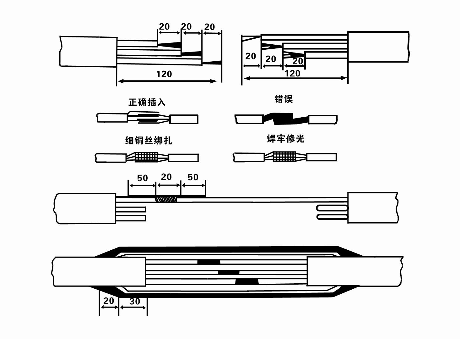
8. Utilisez un multimètre pour vérifier si les fils triphasés sont connectés et si la résistance CC est approximativement équilibrée.
9. Vérifiez si le circuit et la capacité du transformateur sont surchargés, puis connectez l'interrupteur de protection contre les surcharges ou l'équipement de démarrage. Voir le tableau 2 pour les modèles spécifiques, puis versez un seau d'eau dans la pompe à eau depuis la sortie de la pompe à eau pour lubrifier les roulements en caoutchouc de la pompe, puis placez la pompe électrique submersible verticale et stable. Démarrez (pas plus d'une seconde) et vérifiez si la direction de direction est cohérente avec le panneau de direction. Sinon, échangez deux connecteurs du câble triphasé. Installez ensuite le filtre et préparez-vous à descendre dans le puits. Si elle est utilisée dans des occasions spéciales (telles que fossés, fossés, rivières, étangs, étangs, etc.), la pompe électrique doit être mise à la terre de manière fiable.
(2)Équipement et outils d'installation :
1. Une paire de chaînes de levage pour plus de deux tonnes.
2. Un trépied d'une hauteur verticale d'au moins quatre mètres.
3. Deux cordes suspendues (câbles métalliques) pouvant supporter un poids de plus d'une tonne (peuvent supporter le poids d'un ensemble complet de pompes à eau).
4. Installez deux paires de pinces (attelles).
5. Clés, marteaux, tournevis, outils et instruments électriques, etc.
(3)Installation de pompe électrique :
1. Le schéma d'installation de l'électropompe submersible est illustré à la figure 2. Les dimensions d'installation spécifiques sont indiquées dans le tableau 3 « Liste des dimensions d'installation de l'électropompe submersible ».
2. Les pompes électriques submersibles d'une hauteur inférieure à 30 mètres peuvent être hissées directement dans le puits à l'aide de tuyaux et de câbles métalliques ou d'autres câbles de chanvre pouvant supporter tout le poids de la machine entière, des conduites d'eau et de l'eau dans les conduites.
3. Les pompes d'une hauteur de plus de 30 mètres utilisent des tuyaux en acier et la séquence d'installation est la suivante :
①Utilisez une pince pour serrer l'extrémité supérieure de la partie de la pompe à eau (le moteur et la pompe à eau ont été connectés à ce moment-là), soulevez-la avec une chaîne suspendue et attachez-la lentement dans le puits jusqu'à ce que vous mettiez la pince sur la tête de puits et retirez le chaîne suspendue.
② Utilisez une autre paire de colliers pour serrer un tuyau, soulevez-le avec une chaîne suspendue à 15 cm de la bride et abaissez-le lentement. Entre la bride du tuyau et la bride de la pompeMettez le tampon en caoutchouc en place et serrez le tuyau et la pompe uniformément avec des boulons, des écrous et des rondelles élastiques.
③ Soulevez légèrement la pompe submersible, retirez la pince à l'extrémité supérieure de la pompe à eau, attachez fermement le câble à la conduite d'eau avec un ruban en plastique et attachez-le lentement jusqu'à ce que la pince soit placée à la tête de puits.
④Utilisez la même méthode pour relier toutes les conduites d’eau au puits.
⑤ Une fois le câble de sortie connecté à l'interrupteur de commande, il est connecté à l'alimentation triphasée.
(4) Choses à noter lors de l’installation :
1. Si un phénomène de blocage est détecté pendant le processus de pompage, tournez ou tirez sur la conduite d'eau pour surmonter le point de blocage. Si diverses mesures ne fonctionnent toujours pas, veuillez ne pas forcer la pompe vers le bas pour éviter d'endommager la pompe électrique submersible et le puits.
2. Lors de l'installation, un tampon en caoutchouc doit être placé sur la bride de chaque tuyau et serré uniformément.
3. Lorsque la pompe à eau est abaissée dans le puits, elle doit être placée au milieu du tuyau du puits pour empêcher la pompe de fonctionner contre la paroi du puits pendant une longue période, provoquant ainsi la vibration de la pompe et le balayage et la combustion du moteur. .
4. Déterminez la profondeur de la pompe à eau jusqu'au fond du puits en fonction des conditions d'écoulement du sable et du limon du puits. N'enfouissez pas la pompe dans la boue. La distance entre la pompe à eau et le fond du puits n'est généralement pas inférieure à 3 mètres (voir Figure 2).
5. La profondeur d'entrée de l'eau de la pompe à eau ne doit pas être inférieure à 1 à 1,5 mètres entre le niveau d'eau dynamique et le nœud d'entrée d'eau (voir Figure 2). Sinon, les roulements de la pompe à eau pourraient être facilement endommagés.
6. La levée de la pompe à eau ne peut pas être trop faible. Sinon, un robinet-vanne doit être installé sur la canalisation d'eau de la tête de puits pour contrôler le débit de la pompe au point de débit nominal afin d'éviter que le moteur ne soit surchargé et grillé en raison de débits élevés.
7. Lorsque la pompe à eau fonctionne, le débit d'eau doit être continu et uniforme, le courant doit être stable (dans les conditions de travail nominales, généralement pas plus de 10 % du courant nominal) et il ne doit y avoir aucune vibration ni bruit. En cas d'anomalie, la machine doit être arrêtée pour en rechercher la cause et l'éliminer.
8. Lors de l'installation, faites attention au réglage du fil de terre du moteur (voir Figure 2). Lorsque la conduite d'eau est un tuyau en acier, faites-la sortir du collier de serrage de la tête de puits ; lorsque le tuyau d'eau est un tuyau en plastique, faites-le passer du repère de mise à la terre de la pompe électrique.
- 1.After installing the submersible pump, recheck the insulation resistance and the three-phase continuity at the switch, and check whether there are errors in the connection of the instrument and the starting equipment.If there are no problems, you can start to test the machine. After starting, observe whether the indication readings of each instrument are correct. If the rated voltage and current specified on the nameplate are exceeded, observe whether the pump emits any noise or vibration. If everything is normal, it can be put into operation.
- 2. After the pump runs for the first four hours, the thermal insulation resistance of the motor should be closed and tested quickly.Its value should not be less than 0.5 megaohm.After the pump stops, it should be restarted after an interval of five minutes to prevent the water column in the pipeline from completely reversing and burning the motor due to excessive current.
- 3. After the pump is put into normal operation, in order to prolong its service life, it is necessary to check regularly whether the supply voltage, working current and insulation resistance are normal. If the following conditions are found, the machine should be stopped immediately to troubleshoot.
- 1 Dans les conditions de fonctionnement nominales, le courant dépasse 20 %.
- 2 Le niveau d'eau dynamique descend jusqu'à la section d'entrée d'eau, provoquant une eau intermittente.
- 3 La pompe submersible présente des vibrations ou du bruit importants.
- 4 La tension d'alimentation est inférieure à 340 volts.
- 5 Un fusible est grillé.
- 6 Le tuyau d'alimentation en eau est endommagé.
- 7 La résistance d'isolement du moteur à l'état géothermique est inférieure à 0,5 mégaohm.
- Unit disassembly:
- 1.untie cable rope, remove the pipeline part, remove the wire plate.
- 2.screw down the water bolt, put the water in the motor chamber.
- 3.remove the filter, loose the fixed screw on the coupling to fix the motor shaft.
- 4.screw down the bolt connecting the inlet junction with the motor, and separate the pump from the motor (pay attention to the unit cushion when separating, to prevent the bending of the pump shaft)
- 5.the disassembly sequence of the pump is: (see figure 1) inlet junction, impeller, diversion shell, impeller...... check valve body, when removing the impeller, use special tools to loosen the conical sleeve of the fixed impeller first, and avoid bending and bruising of the pump shaft in the process of disassembly.
- 6.the disassembly process of the motor is: (see figure 1) place the motor on the platform, and remove the nuts, base, shaft head locking nut, thrust plate, key, lower guide bearing seat and double head bolt from the bottom of the motor in turn, and then take out the rotor (pay attention not to damage the wire package) and finally remove the connecting section and upper guide bearing seat.
- 7.unit assembly: before assembly, the rust and dirt of the parts should be cleaned, and the mating surface and fasteners coated with sealant, and then assembled in the reverse order of disassembly (the motor shaft moves up and down after assembly for about one millimeter), after assembly, the coupling should be flexible, and then the filter screen test machine. Submersible pumps shall be taken out of the well for dismantling and maintenance according to Article 5 after a year of operation, or less than a year of operation but two years of diving time, and the worn parts shall be replaced.
This product adopts advanced design and provides advanced storage suggestions to ensure long-term use effect.First of all, in winter, it is necessary to exhaust all the water to prevent freezing. In addition, the wire rolls should be placed well and tied up.Secondly, when storing, the environment without corrosive action and gas should be selected and the temperature should be kept below 40 °C. Finally, when not used for a long time, attention should be paid to prevent rust of submersible pump.These storage requirements will ensure that the product can maintain its performance status and prolong its service life for a long time.
- Turbine
- Manchon d'arbre
- Manchon d'arbre en caoutchouc
-
Bague d'étanchéité
01 Prise d'eau de puits profond
02 Approvisionnement en eau en hauteur
03 approvisionnement en eau de montagne
04 tour d'eau
05 Irrigation agricole
06 arrosage du jardin
07 prise d'eau de rivière
08 eau domestique

