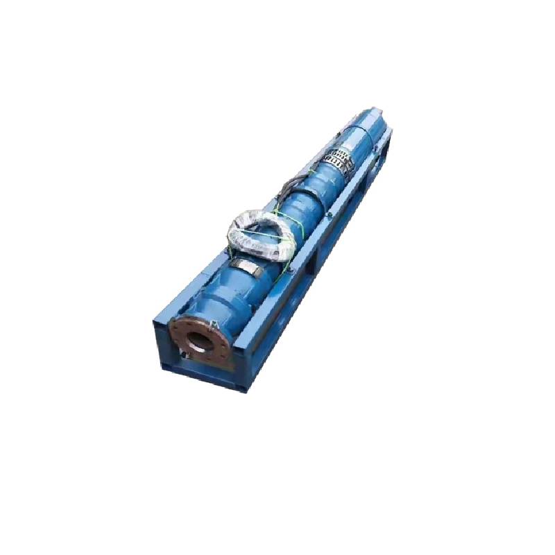
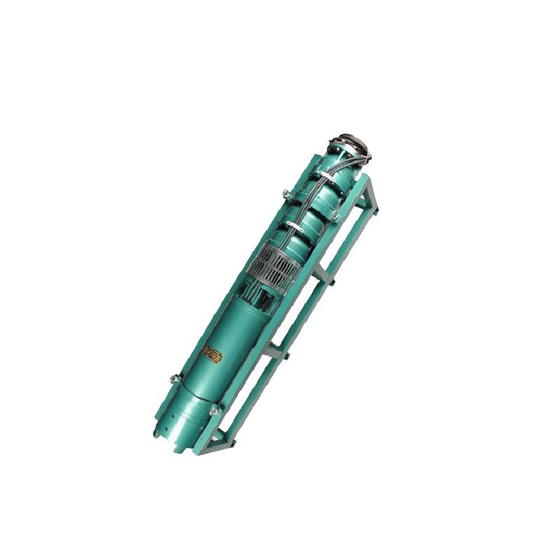
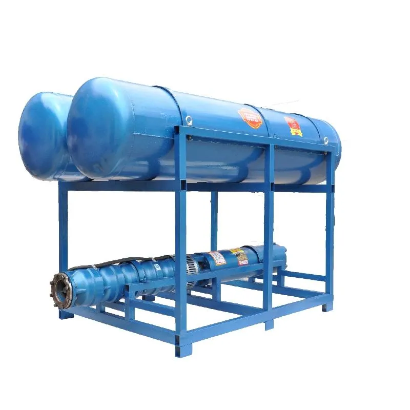
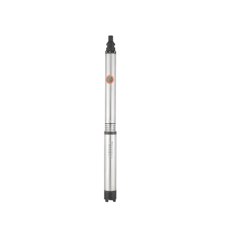
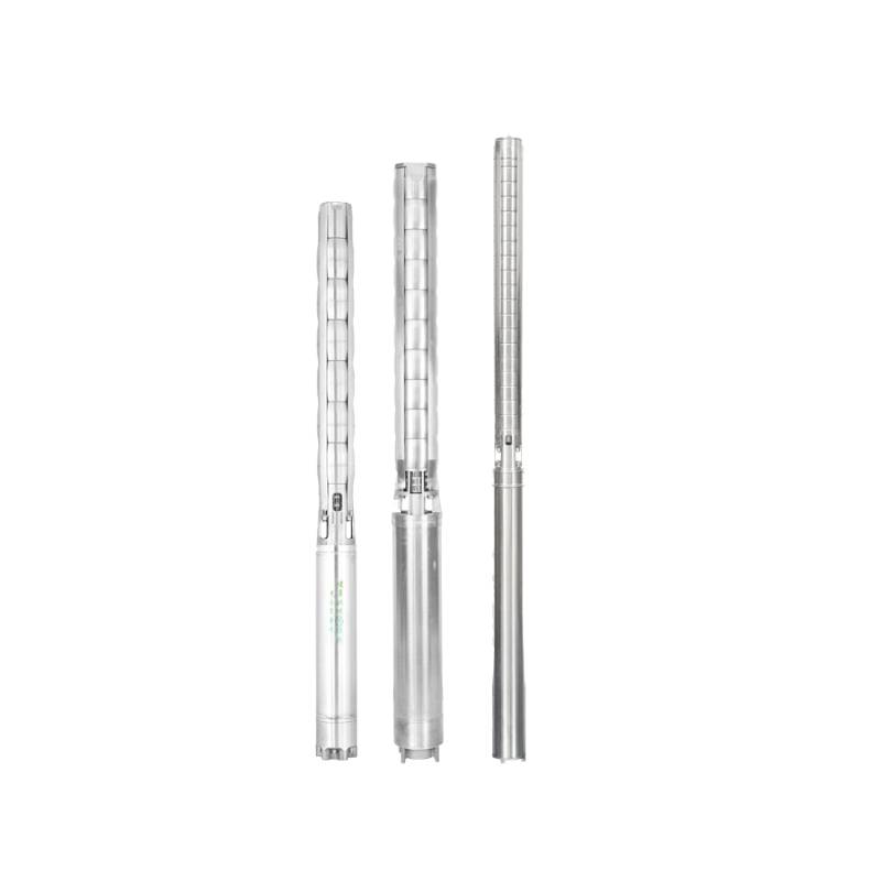
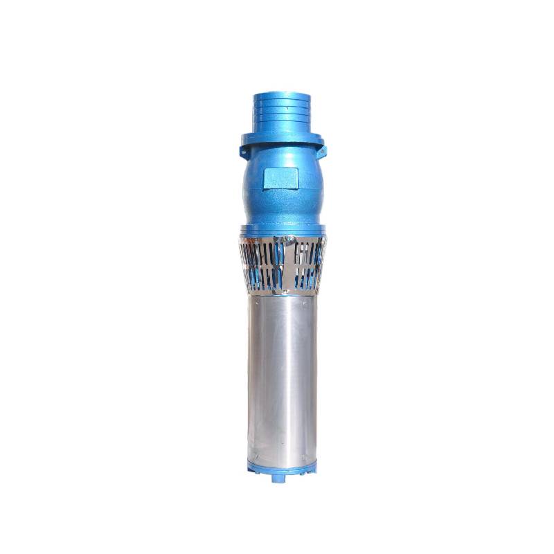
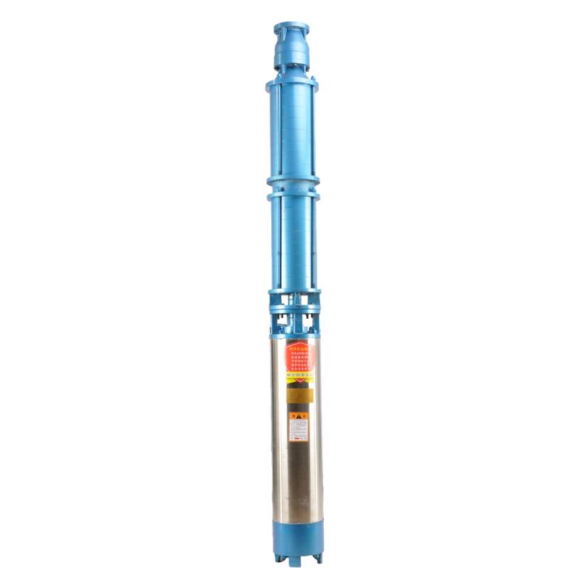
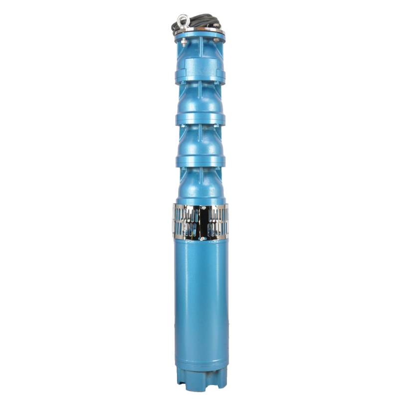
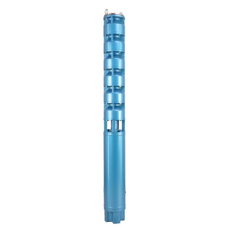
QJP series fountain pump is a special pump for fountain developed by our factory.The pump motor core is made of high quality cold rolled silicon steel, which makes the pump more efficient, good magnetic conductivity, and frequent start will not fever.Both ends of the motor rotor use water as lubricant alloy copper sleeve.Stainless steel sleeve instead of ball bearings, to avoid the problem of easy rust ball bearings and lack of oil wear and tear the motor.The most suitable for music fountain use, all models can be used.
This product is a three-phase AC 380V (tolerance + / - 5%), 50HZ (tolerance + / - 1%) power supply system. Applicable water quality conditions include water temperature not exceeding 20 °C, solid impurities content (mass ratio) is not greater than 0.01%, PH value (pH) is 6.5-8.5, hydrogen sulfide content is not greater than 1.5mg/L, chloride ion content is not greater than 400mg/L. The motor is a closed or water-filled wet structure. Before use, it must be filled with clean water to prevent false filling, and then tighten the water injection and exhaust bolts, otherwise it is not allowed to use. The submersible pump must be completely immersed in water, and the penetration depth shall not exceed 70m. The distance between the submersible pump base and the bottom of the well shall not be less than 3m. The well flow shall be able to meet the water output and continuous operation of the submersible pump. The water output of the submersible pump shall be controlled at 0.7-1.2 times of the rated flow. The well shall be vertical, and the submersible pump can not be used horizontally or upside down, but only vertically. The submersible pump shall be equipped with cables and external overload protection devices as required. The pump is strictly prohibited from no-load test without water.
| Model | Stroom (m3/u) | Hoofd (M) |
Rotatiesnelheid (verandering/punt) |
Waterpomp(%) | Uitlaat diameter (mm) |
Goed toepasbaar diameter (mm) |
Beoordeeld power(KW) |
Beoordeeld spanning (V) |
Beoordeeld stroom (A) |
Motorefficiëntie (%) | power factorcosφ | Eenheid Radiale maximale maat (mm) |
|||||||||
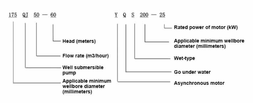
| 175QJ10-42 | 10 | 42 | 2850 | 53 | 50 | 175boven | 3 | 380 | 7.8 | 74.0 | 0.79 | 168 | |||||||||
| 175QJ10-56 | 56 | 4 | 10.1 | 76.0 | 0.79 | ||||||||||||||||
| 175QJ10-70 | 70 | 4 | 10.1 | 76.0 | 0.79 | ||||||||||||||||
| 175QJ10-84 | 84 | 5.5 | 13.6 | 77.0 | 0.8 | ||||||||||||||||
| 175QJ10-112 | 112 | 7.5 | 18.4 | 77.5 | 0.8 | ||||||||||||||||
| 175QJ10-126 | 126 | 7.5 | 18.4 | 77.5 | 0.8 | ||||||||||||||||
| 175QJ10-140 | 140 | 9.2 | 22.1 | 78.0 | 0.81 | ||||||||||||||||
| 175QJ15-42 | 15 | 42 | 2850 | 58 | 50 | 175boven | 4 | 380 | 10.1 | 76.0 | 0.79 | 168 | |||||||||
| 175QJ15-55 | 55 | 5.5 | 13.6 | 77.0 | 0.8 | ||||||||||||||||
| 175QJ15-65 | 65 | 5.5 | 13.6 | 77.0 | 0.8 | ||||||||||||||||
| 175QJ15-85 | 85 | 7.5 | 18.4 | 77.5 | 0.8 | ||||||||||||||||
| 175QJ15-112 | 112 | 9.2 | 22.1 | 78.0 | 0.81 | ||||||||||||||||
| 175QJ20-26 | 20 | 26 | 2850 | 64 | 50 | 175boven | 3 | 380 | 7.8 | 74.0 | 0.79 | 168 | |||||||||
| 175QJ20-39 | 39 | 4 | 10.1 | 76.0 | 0.79 | ||||||||||||||||
| 175QJ20-52 | 52 | 5.5 | 13.6 | 77.0 | 0.8 | ||||||||||||||||
| 175QJ20-78 | 78 | 7.5 | 18.4 | 77.5 | 0.8 | ||||||||||||||||
| 175QJ20-91 | 91 | 9.2 | 22.1 | 78.0 | 0.81 | ||||||||||||||||
| 175QJ20-104 | 104 | 11 | 26.1 | 79.0 | 0.81 | ||||||||||||||||
| 175QJ20-130 | 130 | 13 | 30.1 | 80.0 | 0.82 | ||||||||||||||||
| 175QJ20-156 | 156 | 15 | 34.7 | 80.0 | 0.82 | ||||||||||||||||
| 175QJ20-182 | 187 | 18.5 | 42.6 | 80.5 | 0.82 | ||||||||||||||||
| 175QJ20-208 | 208 | 22 | 49.7 | 81.0 | 0.83 | ||||||||||||||||
| 175QJ20-247 | 247 | 25 | 56.5 | 81.0 | 0.83 | ||||||||||||||||
| 175QJ20-273 | 273 | 30 | 66.6 | 81.5 | 0.84 | ||||||||||||||||
| 175QJ20-299 | 299 | 30 | 66.6 | 81.5 | 0.84 | ||||||||||||||||
| 175QJ20-325 | 325 | 32 | 71.0 | 81.5 | 0.84 | ||||||||||||||||
| 175QJ20-364 | 364 | 37 | 82.1 | 81.5 | 0.84 | ||||||||||||||||
| 175QJ25-26 | 25 | 26 | 2850 | 66 | 65 | 175boven | 3 | 380 | 7.8 | 74.0 | 0.79 | 168 | |||||||||
| 175QJ25-39 | 39 | 5.5 | 13.6 | 77.0 | 0.8 | ||||||||||||||||
| 175QJ25-65 | 25 | 65 | 2850 | 66 | 65 | 175boven | 7.5 | 380 | 18.4 | 77.5 | 0.8 | 168 | |||||||||
| 175QJ25-78 | 78 | 9.2 | 22.1 | 78.0 | 0.81 | ||||||||||||||||
| 175QJ25-91 | 91 | 11 | 26.1 | 79.0 | 0.81 | ||||||||||||||||
| 175QJ25-104 | 104 | 13 | 30.1 | 80.0 | 0.82 | ||||||||||||||||
| 175QJ25-130 | 130 | 15 | 34.7 | 80.0 | 0.82 | ||||||||||||||||
| 175QJ25-156 | 156 | 18.5 | 42.6 | 80.5 | 0.82 | ||||||||||||||||
| 175QJ25-182 | 182 | 22 | 49.7 | 81.0 | 0.83 | ||||||||||||||||
| 175QJ25-208 | 208 | 25 | 56.5 | 81.0 | 0.83 | ||||||||||||||||
| 175QJ25-221 | 221 | 30 | 66.6 | 81.5 | 0.84 | ||||||||||||||||
| 175QJ25-247 | 247 | 30 | 66.6 | 81.5 | 0.84 | ||||||||||||||||
| 175QJ25-260 | 260 | 32 | 71.0 | 81.5 | 0.84 | ||||||||||||||||
| 175QJ25-299 | 299 | 37 | 82.1 | 81.5 | 0.84 | ||||||||||||||||
| 175QJ30-30 | 30 | 30 | 2850 | 67 | 80 | 175boven | 4 | 380 | 10.1 | 76.0 | 0.79 | 168 | |||||||||
| 175QJ30-40 | 40 | 5.5 | 13.6 | 77.0 | 0.8 | ||||||||||||||||
| 175QJ32-24 | 32 | 24 | 2850 | 67 | 80 | 175boven | 4 | 380 | 10.1 | 76.0 | 0.79 | 168 | |||||||||
| 175QJ32-36 | 36 | 5.5 | 13.6 | 77.0 | 0.8 | ||||||||||||||||
| 175QJ32-48 | 48 | 7.5 | 18.4 | 77.5 | 0.8 | ||||||||||||||||
| 175QJ32-60 | 60 | 9.2 | 22.1 | 78.0 | 0.81 | ||||||||||||||||
| 175QJ32-72 | 72 | 11 | 26.1 | 79.0 | 0.81 | ||||||||||||||||
| 175QJ32-84 | 84 | 13 | 30.1 | 80.0 | 0.82 | ||||||||||||||||
| 175QJ32-96 | 96 | 15 | 34.7 | 80.0 | 0.82 | ||||||||||||||||
| 175QJ32-120 | 120 | 18.5 | 42.6 | 80.5 | 0.82 | ||||||||||||||||
| 175QJ32-144 | 144 | 22 | 49.7 | 81.0 | 0.83 | ||||||||||||||||
| 175QJ32-168 | 168 | 25 | 56.5 | 81.0 | 0.83 | ||||||||||||||||
| 175QJ32-180 | 180 | 30 | 66.6 | 81.5 | 0.84 | ||||||||||||||||
| 175QJ32-192 | 192 | 30 | 66.6 | 81.5 | 0.84 | ||||||||||||||||
| 175QJ32-204 | 204 | 32 | 71.0 | 81.5 | 0.84 | ||||||||||||||||
| 175QJ32-240 | 240 | 37 | 82.1 | 81.5 | 0.84 | ||||||||||||||||
| 175QJ35-60 | 35 | 60 | 2850 | 67 | 80 | 175boven | 10 | 380 | 25.0 | 78.0 | 0.78 | 168 | |||||||||
| 175QJ35-75 | 75 | 13 | 30.1 | 80.0 | 0.82 | ||||||||||||||||
| 175QJ35-100 | 100 | 17 | 40.9 | 80.0 | 0.79 | ||||||||||||||||
| 175QJ40-24 | 40 | 24 | 2850 | 70 | 80 | 175boven | 5.5 | 380 | 13.6 | 77.0 | 0.8 | 168 | |||||||||
| 175QJ40-30 | 30 | 5.5 | 13.6 | 77.0 | 0.8 | ||||||||||||||||
| 175QJ40-36 | 36 | 7.5 | 18.4 | 77.5 | 0.8 | ||||||||||||||||
| 175QJ40-48 | 48 | 9.2 | 22.1 | 78.0 | 0.81 | ||||||||||||||||
| 175QJ40-60 | 60 | 11 | 26.1 | 79.0 | 0.81 | ||||||||||||||||
| 175QJ40-72 | 72 | 13 | 30.1 | 80.0 | 0.82 | ||||||||||||||||
| 175QJ40-84 | 84 | 15 | 34.7 | 80.0 | 0.82 | ||||||||||||||||
| 175QJ40-96 | 96 | 18.5 | 42.6 | 80.5 | 0.82 | ||||||||||||||||
| 175QJ40-120 | 120 | 22 | 49.7 | 81.0 | 0.83 | ||||||||||||||||
| 175QJ40-132 | 132 | 25 | 56.5 | 81.0 | 0.83 | ||||||||||||||||
| 175QJ40-144 | 144 | 30 | 66.6 | 81.5 | 0.84 | ||||||||||||||||
| 175QJ40-156 | 156 | 30 | 66.6 | 81.5 | 0.84 | ||||||||||||||||
| 175QJ40-168 | 168 | 32 | 71.0 | 81.5 | 0.84 | ||||||||||||||||
| 175QJ40-192 | 192 | 37 | 82.1 | 81.5 | 0.84 | ||||||||||||||||
| 175QJ50-24 | 50 | 24 | 2850 | 72 | 80 | 175boven | 5.5 | 380 | 13.6 | 77.0 | 0.8 | 168 | |||||||||
| 175QJ50-36 | 36 | 9.2 | 22.1 | 78.0 | 0.81 | ||||||||||||||||
| 175QJ50-48 | 48 | 11 | 26.1 | 79.0 | 0.81 | ||||||||||||||||
| 175QJ50-60 | 60 | 13 | 30.1 | 80.0 | 0.82 | ||||||||||||||||
| 175QJ50-70 | 70 | 17 | 40.9 | 80.0 | 0.79 | ||||||||||||||||
| 175QJ50-84 | 84 | 18.5 | 42.6 | 80.5 | 0.82 | ||||||||||||||||
| 175QJ50-96 | 96 | 22 | 49.7 | 81.0 | 0.83 | ||||||||||||||||
| 175QJ50-108 | 108 | 25 | 56.5 | 81.0 | 0.83 | ||||||||||||||||
| 175QJ50-120 | 120 | 30 | 66.6 | 81.5 | 0.84 | ||||||||||||||||
| 175QJ50-132 | 132 | 30 | 66.6 | 81.5 | 0.84 | ||||||||||||||||
| 175QJ50-144 | 144 | 32 | 71.0 | 81.5 | 0.84 | ||||||||||||||||
| 175QJ50-156 | 156 | 37 | 82.1 | 81.5 | 0.84 | ||||||||||||||||
| 175QJ63-22 | 63 | 22 | 2850 | 72 | 80 | 175boven | 7.5 | 380 | 18.4 | 77.5 | 0.8 | 168 | |||||||||
| 175QJ63-44 | 44 | 13 | 30.1 | 80.0 | 0.82 | ||||||||||||||||
| 175QJ63-55 | 55 | 15 | 34.7 | 80.0 | 0.82 | ||||||||||||||||
| 175QJ63-66 | 66 | 18.5 | 42.6 | 80.5 | 0.82 | ||||||||||||||||
| 175QJ63-77 | 77 | 22 | 49.7 | 81.0 | 0.83 | ||||||||||||||||
| 175QJ63-88 | 88 | 25 | 56.5 | 81.0 | 0.83 | ||||||||||||||||
| 175QJ63-99 | 63 | 99 | 2850 | 72 | 80 | 175boven | 30 | 380 | 66.6 | 81.5 | 0.84 | 168 | |||||||||
| 175QJ63-110 | 110 | 32 | 71.0 | 81.5 | 0.84 | ||||||||||||||||
| 175QJ63-132 | 132 | 37 | 82.1 | 81.5 | 0.84 | ||||||||||||||||
| 175QJ80-9 | 80 | 9 | 2850 | 73 | 100 | 175boven | 4 | 380 | 10.1 | 76.0 | 0.79 | 168 | |||||||||
| 175QJ80-18 | 18 | 7.5 | 18.4 | 77.5 | 0.8 | ||||||||||||||||
| 175QJ80-27 | 27 | 11 | 26.1 | 79.0 | 0.81 | ||||||||||||||||
| 175QJ80-36 | 36 | 15 | 34.7 | 80.0 | 0.82 | ||||||||||||||||
| 175QJ80-45 | 45 | 18.5 | 42.6 | 80.5 | 0.82 | ||||||||||||||||
| 175QJ80-54 | 54 | 22 | 49.7 | 81.0 | 0.83 | ||||||||||||||||
| 175QJ80-63 | 63 | 25 | 56.5 | 81.0 | 0.83 | ||||||||||||||||
| 175QJ80-72 | 72 | 25 | 56.5 | 81.0 | 0.83 | ||||||||||||||||
| 175QJ80-81 | 81 | 30 | 66.6 | 81.5 | 0.84 | ||||||||||||||||
| 175QJ80-90 | 90 | 32 | 71.0 | 81.5 | 0.84 | ||||||||||||||||
| 175QJ80-98 | 98 | 37 | 82.1 | 81.5 | 0.84 | ||||||||||||||||
1, well submersible pump for clean water pump, prohibit the new well, pumping sediment and muddy water,
2, well water pump voltage grade of 380/50HZ, the use of other voltage grades of submersible motors need to be customized. The underground cable must use waterproof cable, must be equipped with starting equipment, such as distribution box, start not ready should have commonly used motor comprehensive protection function, such as short circuit overload protection, phase protection, undervoltage protection, grounding protection, idling protection, in case of abnormal conditions, the protection device should be timely action trip.
3, the installation and use of the pump must be reliably grounded, prohibit the push and pull switch when the hands and feet are wet, the installation and maintenance of the pump must be cut off the power supply, the use of the pump place to set up "to prevent electric shock" obvious signs:
4, down the well or before installation, the motor cavity must be filled with distilled water or non-corrosive clean cold boiling water, tighten the / water bolt, the pump on the ground test run, must be to the pump chamber water lubrication rubber bearings, instant start not more than a second, see whether the steering is the same as the steering instructions. When the pump is upright, pay attention to safety, prevent overturning injury.
5, strikt volgens de bepalingen van de pomplift, stroombereik van gebruik, om lage stroom of hoge pompkracht, het druklager en andere delen van de slijtage te voorkomen, verbrandt de motoroverbelasting
6, after the pump down the well, the measurement of the motor to the ground insulation resistance should not be less than 100M, after the start to observe the voltage and current, check the motor winding insulation, whether in line with the requirements; pump storage location temperature if less than freezing point, should be dry the motor cavity water, prevent the motor cavity water ice damage caused by low temperature.
The pump part is mainly composed of pump shaft, impeller, shunt shell, rubber bearing, check valve body (optional) and other components. The motor part mainly includes base, pressure regulating diaphragm, thrust bearing, thrust plate, lower guide bearing seat, stator, rotor, upper guide bearing seat, sand ring, water inlet section, lead cable and other components. The main features of the product include: the motor is a water immersed wet three-phase asynchronous motor, the motor cavity is full of water, used to cool the motor and lubricate the bearing; the pressure regulating film at the bottom of the motor is used to adjust the expansion and contraction pressure difference of the internal water caused by the change of temperature; in order to prevent the sand particles in the well water from entering the motor, two oil seals are installed on the upper end of the motor shaft extension, and a sand control structure is formed by installing the sand ring; in order to prevent the pump shaft from jumping at startup, the pump shaft is connected with the motor shaft through a coupling, and the thrust bearing is installed under the motor; the lubrication of the motor and the pump bearing is water lubrication; the stator winding of the motor is made of high quality submersible motor winding, with high insulation performance; the pump is designed by computer CAD, with simple structure and excellent technical performance.

(1)Voorbereiding vóór installatie:
1. Controleer of de dompelpomp voldoet aan de gebruiksvoorwaarden en toepassingsgebied zoals aangegeven in de handleiding.
2. Meet met behulp van een zwaar voorwerp met een diameter gelijk aan de maximale buitendiameter van de dompelpomp of de binnendiameter van het boorgat in de dompelpomp past en meet of de putdiepte voldoet aan de installatievereisten.
3. Controleer of het boorgat schoon is en of het bronwater troebel is. Gebruik nooit een elektrische dompelpomp om modder- en zandwater van de welorpomp te spoelen om voortijdige schade aan de elektrische dompelpomp te voorkomen.
4. Controleer of de positie van de welhead-installatieklem geschikt is en of deze bestand is tegen de kwaliteit van de gehele unit
5. Controleer of de onderdelen van de dompelpomp compleet zijn en correct zijn geïnstalleerd volgens het montageschema in de handleiding. Verwijder het filterscherm en draai de koppeling om te zien of deze soepel draait
6. Draai de waterschroef los en vul de motorruimte met schoon, niet-corrosief water (let op: zorg ervoor dat u deze opvult) en draai vervolgens de waterschroef vast. Na 12 uur waterinjectie mag de isolatieweerstand van de motor niet minder zijn dan 150M Q, gemeten met een schudtafel van 500V.
7. Cable joint, cut off a 120mm rubber sleeve from one end of the outgoing cable and the matching cable with an electrician's knifethen stagger the length of the three core wires in a stepped shape, peel off a 20mm copper core, scrape of the oxide layer on theoutside of the copper wire with a knife or sand cloth, and insert the two connected wire ends in palirs.After tying the layer tightly with fine copper wire, solder it thoroughly and firmly, and sand of any. burrs on the surface. Then, forthe three joints, use polyvester insulation tape to wrap them in a semi stacked manner for three lavers. Wrap the two ends of thewrapping layer tightywith nyion thread,and then use a semi stacked method to wrap the tape for three layers. Wrap the outellayer with high-pressure insulation tape for three layers. Finally, fold the threestrands together and repeatedly wrap them for fivelayers with high-pressure tape. Each layer must be tightly tied, and the interlayer joints must be tight and fimm to prevent water frompenetrating and damaging the insulation, After wrapping, soak in water at room temperature of 20 ’c for 12 hours, and measurethe insulation resistance with a shaking table, which should not be less than 100M Ω
Het bijgevoegde processchema voor de kabelbedrading is als volgt: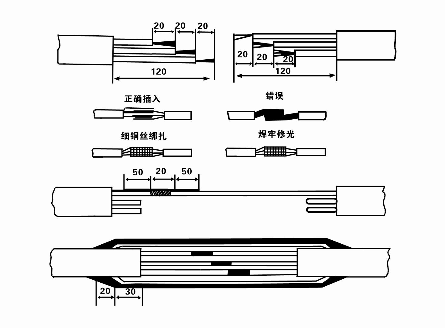
8. Controleer met een multimeter of de driefasige draden zijn aangesloten en of de DC-weerstand ongeveer in evenwicht is.
9. Controleer of de circuit- en transformatorcapaciteit overbelast zijn en sluit vervolgens de overbelastingsbeveiligingsschakelaar of startapparatuur aan. Zie Tabel 2 voor specifieke modellen en giet vervolgens een emmer water in de waterpomp vanaf de waterpompuitlaat om de rubberen lagers in de pomp te smeren, en plaats vervolgens de elektrische dompelpomp rechtop en stabiel. Start (niet meer dan één seconde) en controleer of de stuurrichting overeenkomt met het stuurteken. Als dit niet het geval is, verwissel dan twee willekeurige connectoren van de driefasige kabel. Installeer vervolgens het filter en bereid u voor om de put in te gaan. Bij gebruik in speciale gelegenheden (zoals sloten, sloten, rivieren, vijvers, vijvers, etc.) moet de elektrische pomp betrouwbaar geaard zijn.
(2) Installatieapparatuur en gereedschappen:
1. Eén paar hijskettingen voor meer dan twee ton.
2. Een statief met een verticale hoogte van minimaal vier meter.
3. Twee ophangtouwen (staalkabels) die een gewicht van meer dan één ton kunnen dragen (kunnen het gewicht van een complete set waterpompen dragen).
4. Installeer twee paar klemmen (spalken).
5. Sleutels, hamers, schroevendraaiers, elektrisch gereedschap en instrumenten, enz.
(3)Elektrische pompinstallatie:
1. Het installatieschema van de elektrische dompelpomp wordt weergegeven in Figuur 2. De specifieke installatieafmetingen worden weergegeven in Tabel 3 "Lijst met installatieafmetingen van de elektrische dompelpomp".
2. Elektrische dompelpompen met een opvoerhoogte van minder dan 30 meter kunnen rechtstreeks in de put worden gehesen met behulp van slangen en staalkabels of andere hennepkabels die het volledige gewicht van de hele machine, waterleidingen en water in de leidingen kunnen dragen.
3. Pompen met een opvoerhoogte van meer dan 30 meter gebruiken stalen buizen en de installatievolgorde is als volgt:
①Gebruik een klem om het bovenste uiteinde van het waterpompgedeelte vast te klemmen (de motor en de waterpomp zijn op dit moment aangesloten), til het op met een hangende ketting en bind het langzaam in de put totdat u de klem op de putmond plaatst en verwijder de hangende ketting.
② Gebruik een ander paar klemmen om een buis vast te klemmen, til deze op met een hangende ketting op 15 cm afstand van de flens en laat hem langzaam zakken. Tussen leidingflens en pompflens Plaats het rubberen kussentje en draai de leiding en pomp gelijkmatig vast met bouten, moeren en veerringen.
③ Til de dompelpomp iets op, verwijder de klem aan het bovenste uiteinde van de waterpomp, bind de kabel stevig aan de waterleiding met plastic tape en bind hem langzaam vast totdat de klem bij de putmond is geplaatst.
④Gebruik dezelfde methode om alle waterleidingen in de put te verbinden.
⑤Nadat de uitgangskabel op de bedieningsschakelaar is aangesloten, wordt deze aangesloten op de driefasige voeding.
(4) Waar u op moet letten tijdens de installatie:
1. Als er tijdens het pompproces een vastlopend verschijnsel wordt geconstateerd, draai of trek dan aan de waterleiding om het vastgelopen punt te overwinnen. Als verschillende maatregelen nog steeds niet werken, forceer de pomp dan niet om schade aan de elektrische dompelpomp en de put te voorkomen.
2. Tijdens de installatie moet een rubberen kussentje op de flens van elke buis worden geplaatst en gelijkmatig worden vastgedraaid.
3. Wanneer de waterpomp in de put wordt neergelaten, moet deze in het midden van de putpijp worden geplaatst om te voorkomen dat de pomp lange tijd tegen de putwand loopt, waardoor de pomp gaat trillen en de motor gaat vegen en verbranden .
4. Bepaal de diepte van de waterpomp tot de bodem van de put, afhankelijk van de stromende zand- en slibcondities van de put. Begraaf de pomp niet in de modder. De afstand van de waterpomp tot de bodem van de put bedraagt doorgaans niet minder dan 3 meter (zie figuur 2).
5. De waterinvoerdiepte van de waterpomp mag niet minder zijn dan 1-1,5 meter vanaf het dynamische waterniveau tot het waterinlaatknooppunt (zie figuur 2). Anders kunnen de lagers van de waterpomp gemakkelijk beschadigd raken.
6. De lift van de waterpomp mag niet te laag zijn. Anders moet er een schuifafsluiter op de waterleiding van de put worden geïnstalleerd om de pompstroom op het nominale stroompunt te regelen om te voorkomen dat de motor overbelast raakt en doorbrandt als gevolg van grote stroomsnelheden.
7. Wanneer de waterpomp draait, moet de wateropbrengst continu en gelijkmatig zijn, moet de stroom stabiel zijn (onder nominale werkomstandigheden, over het algemeen niet meer dan 10% van de nominale stroom) en mogen er geen trillingen of geluiden zijn. Als er een afwijking is, moet de machine worden gestopt om de oorzaak te achterhalen en deze te elimineren.
8. Let bij het installeren op de instelling van de aarddraad van de motor (zie Figuur 2). Als de waterleiding een stalen buis is, leid deze dan vanaf de putkopklem; als de waterleiding een plastic leiding is, leid deze dan vanaf het aardingsmerkteken van de elektrische pomp.
- 1.After installing the submersible pump, recheck the insulation resistance and the three-phase continuity at the switch, and check whether there are errors in the connection of the instrument and the starting equipment.If there are no problems, you can start to test the machine. After starting, observe whether the indication readings of each instrument are correct. If the rated voltage and current specified on the nameplate are exceeded, observe whether the pump emits any noise or vibration. If everything is normal, it can be put into operation.
- 2. After the pump runs for the first four hours, the thermal insulation resistance of the motor should be closed and tested quickly.Its value should not be less than 0.5 megaohm.After the pump stops, it should be restarted after an interval of five minutes to prevent the water column in the pipeline from completely reversing and burning the motor due to excessive current.
- 3. After the pump is put into normal operation, in order to prolong its service life, it is necessary to check regularly whether the supply voltage, working current and insulation resistance are normal. If the following conditions are found, the machine should be stopped immediately to troubleshoot.
- 1 In de nominale werkomstandigheden overschrijdt de stroom 20%.
- 2 Het dynamische waterniveau zakt naar het waterinlaatgedeelte, waardoor er intermitterend water ontstaat.
- 3 De dompelpomp maakt hevige trillingen of lawaai.
- 4 De voedingsspanning is lager dan 340 volt.
- 5 Een zekering is doorgebrand.
- 6 De watertoevoerleiding is beschadigd.
- 7 De isolatieweerstand van de motor tegen de geothermische toestand is lager dan 0,5 megaohm.
- Unit disassembly:
- 1.untie cable rope, remove the pipeline part, remove the wire plate.
- 2.screw down the water bolt, put the water in the motor chamber.
- 3.remove the filter, loose the fixed screw on the coupling to fix the motor shaft.
- 4.screw down the bolt connecting the inlet junction with the motor, and separate the pump from the motor (pay attention to the unit cushion when separating, to prevent the bending of the pump shaft)
- 5.the disassembly sequence of the pump is: (see figure 1) inlet junction, impeller, diversion shell, impeller...... check valve body, when removing the impeller, use special tools to loosen the conical sleeve of the fixed impeller first, and avoid bending and bruising of the pump shaft in the process of disassembly.
- 6.the disassembly process of the motor is: (see figure 1) place the motor on the platform, and remove the nuts, base, shaft head locking nut, thrust plate, key, lower guide bearing seat and double head bolt from the bottom of the motor in turn, and then take out the rotor (pay attention not to damage the wire package) and finally remove the connecting section and upper guide bearing seat.
- 7.unit assembly: before assembly, the rust and dirt of the parts should be cleaned, and the mating surface and fasteners coated with sealant, and then assembled in the reverse order of disassembly (the motor shaft moves up and down after assembly for about one millimeter), after assembly, the coupling should be flexible, and then the filter screen test machine. Submersible pumps shall be taken out of the well for dismantling and maintenance according to Article 5 after a year of operation, or less than a year of operation but two years of diving time, and the worn parts shall be replaced.
This product adopts advanced design and provides advanced storage suggestions to ensure long-term use effect.First of all, in winter, it is necessary to exhaust all the water to prevent freezing. In addition, the wire rolls should be placed well and tied up.Secondly, when storing, the environment without corrosive action and gas should be selected and the temperature should be kept below 40 °C. Finally, when not used for a long time, attention should be paid to prevent rust of submersible pump.These storage requirements will ensure that the product can maintain its performance status and prolong its service life for a long time.
- Waaier
- Schachthuls
- Rubberen asbus
-
Afsluitring
01 Diepe bronwaterinlaat
02 Hoogbouwwatervoorziening
03 bergwatervoorziening
04 torenwater
05 Landbouwirrigatie
06 tuinirrigatie
07 rivierwaterinname
08 huishoudelijk water

