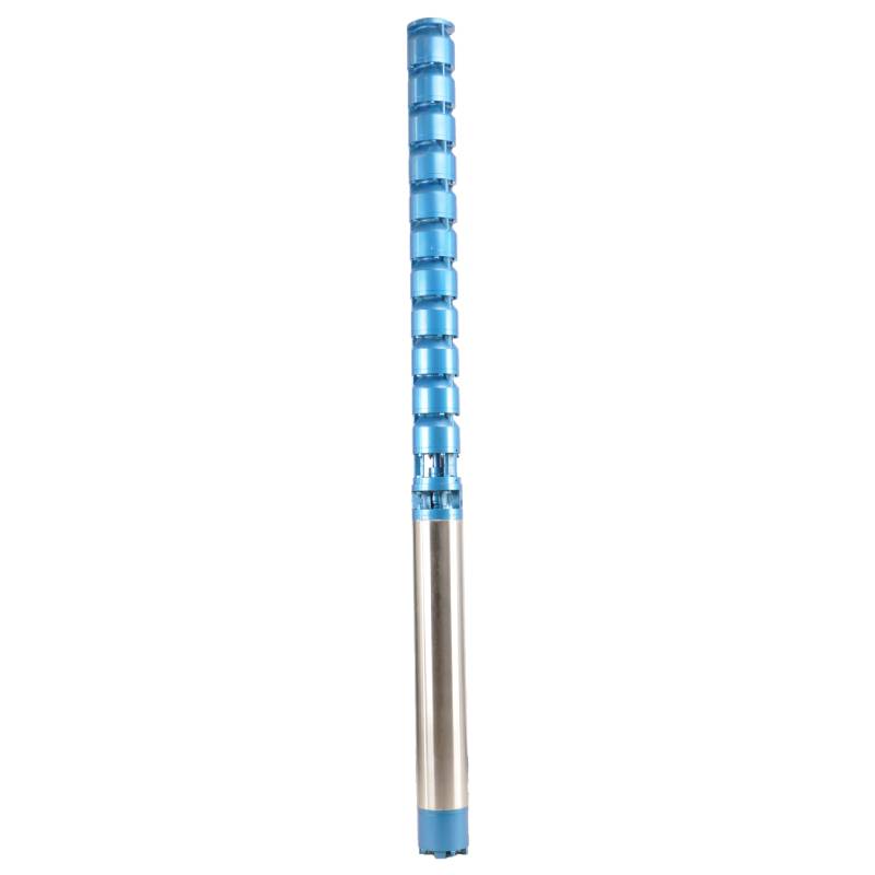
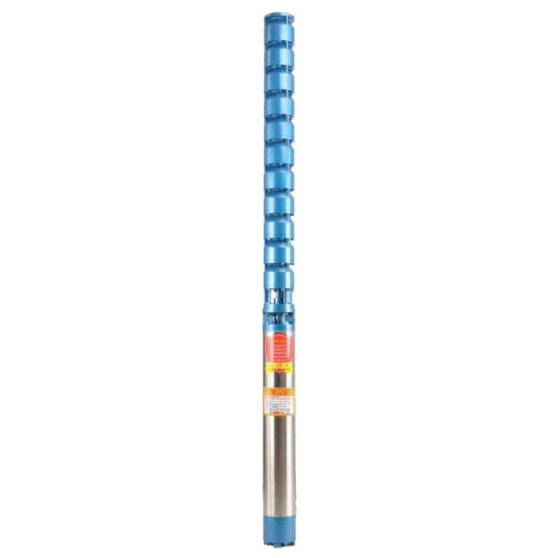
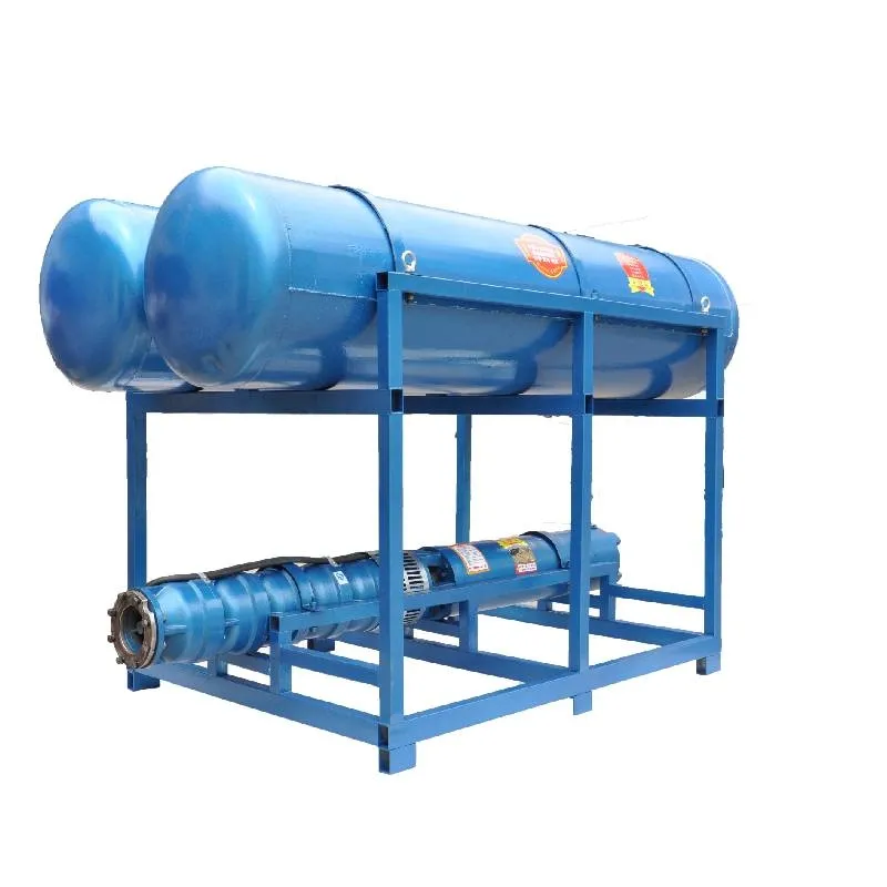
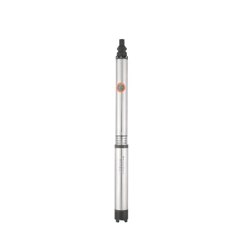
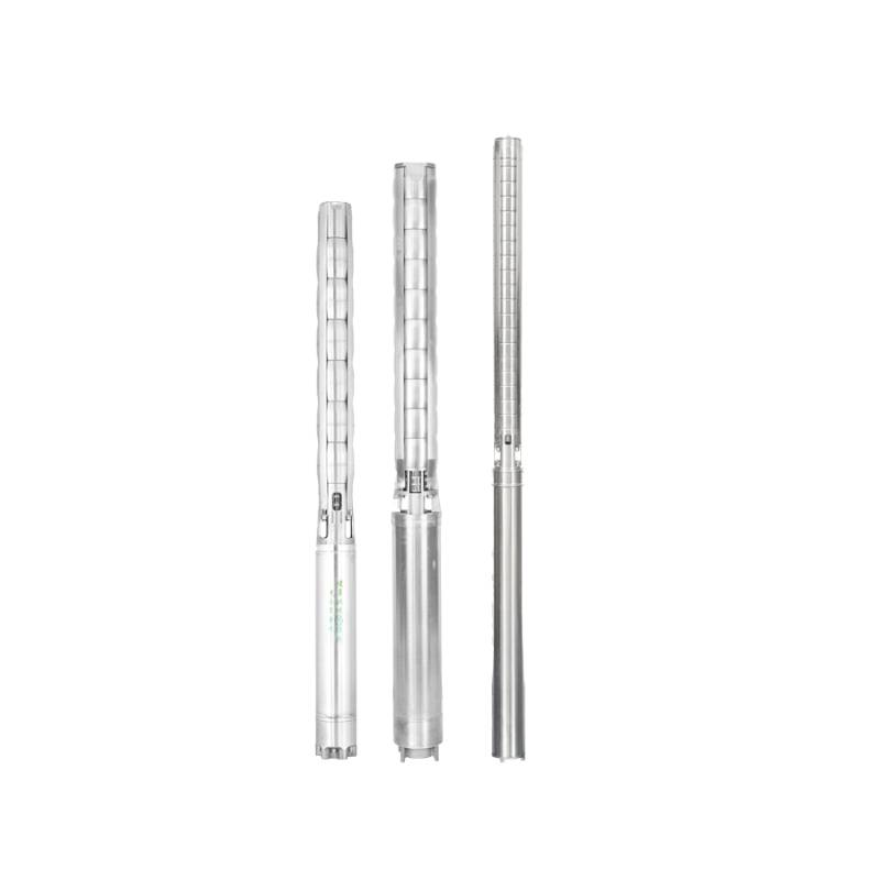
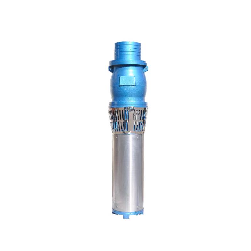
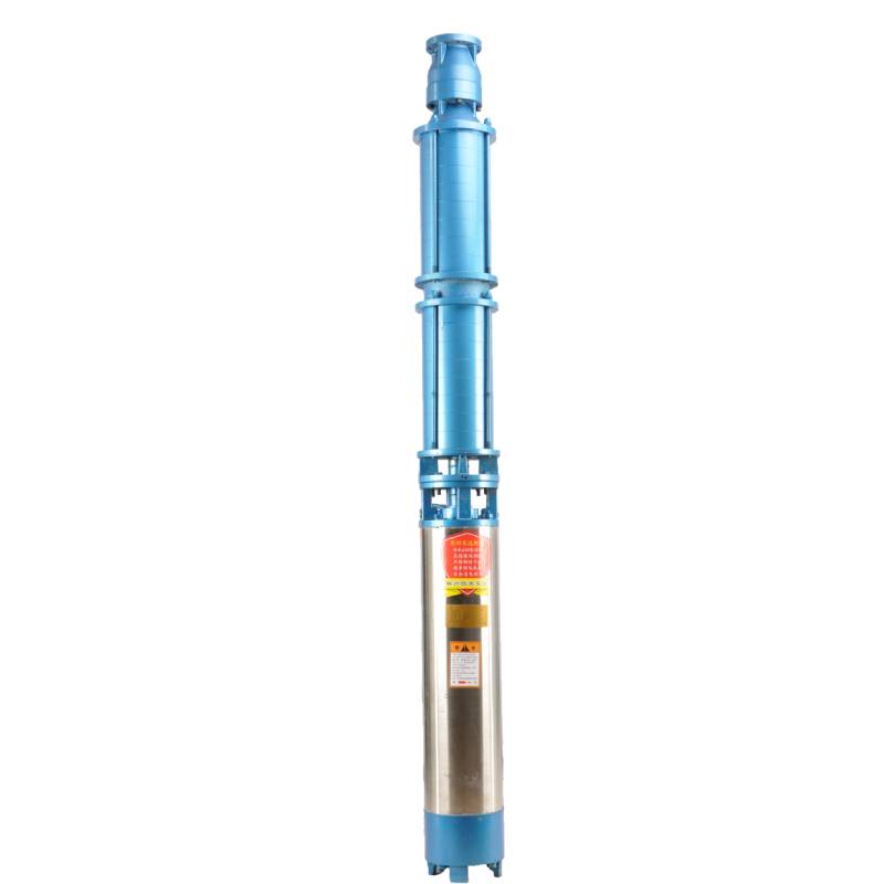
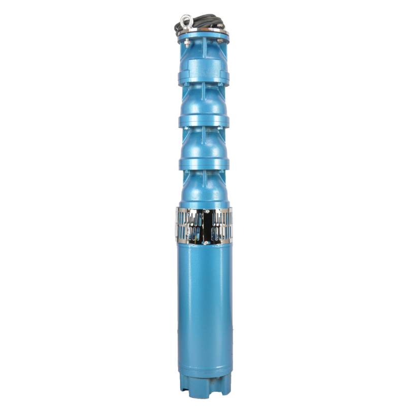
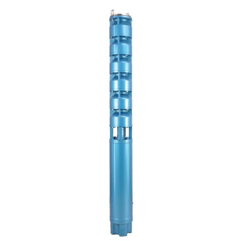
Suitable for underground hot water mining with water temperature below 100°C, with heat resistance, corrosion resistance, aging resistance and other characteristics
This product is a powerful three-phase AC 380V (tolerance ± 5%), 50HZ (tolerance ± 1%) electric pump, suitable for all kinds of occasions need high-power pump. Its design considers a variety of water quality factors, including water temperature not higher than 20 °C, solid impurities content is not greater than 0.01%, PH value is 6.5-8.5, hydrogen sulfide content is not greater than 1.5mg/L, chloride ion content is not greater than 400mg/L, etc. The product adopts a closed or water immersion wet structure of the motor, before use in the submersible motor chamber filled with clean water to prevent empty fill. Requirements in strict accordance with the requirements of the matching cable and equipped with external overload protection device. To ensure stable operation, the submersible pump must be completely immersed in water operation, the insertion depth shall not exceed 70 meters, and the distance from the bottom of the well shall not be less than 3 meters. In addition, the pump shall not be a no-load test before start. In general, this product has the characteristics of high efficiency and stability, suitable for a variety of pump tasks in harsh environment.
| Model | Przepływ (m3/h) | Głowa (M) |
Prędkość obrotowa (zmiana/punkt) |
Pompa wodna(%) | Wylot średnica (mm) |
Dobrze się sprawdza średnica (mm) |
Oceniono moc (KW) |
Oceniono napięcie (V) |
Oceniono prąd (A) |
Sprawność motoryczna (%) | power factorcosφ | Jednostka Maksymalny rozmiar promieniowy (mm) |
Uwaga | |||||||||
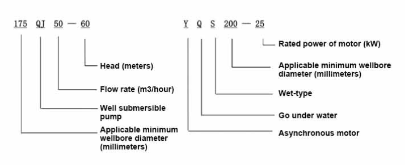
| 125QJ5-34 | 5 | 34 | 2850 | 53 | 40 | 125powyżej | 1.5 | 380 | 4.23 | 70.0 | 0.77 | 118 | ||||||||||
| 125QJ5-51 | 51 | 2.2 | 6.03 | 72.0 | 0.77 | |||||||||||||||||
| 125QJ5-68 | 68 | 3 | 8.01 | 73.0 | 0.78 | |||||||||||||||||
| 125QJ5-85 | 85 | 4 | 10.53 | 74.0 | 0.78 | |||||||||||||||||
| 125QJ5-102 | 102 | 5.5 | 14.1 | 75.0 | 0.79 | |||||||||||||||||
| 125QJ5-119 | 119 | 5.5 | 14.1 | 75.0 | 0.79 | |||||||||||||||||
| 125QJ10-24 | 10 | 24 | 2850 | 60 | 50 | 125powyżej | 1.5 | 380 | 4.23 | 70.0 | 0.77 | 118 | ||||||||||
| 125QJ10-32 | 32 | 2.2 | 6.03 | 72.0 | 0.77 | |||||||||||||||||
| 125QJ10-48 | 48 | 3 | 8.01 | 73.0 | 0.78 | |||||||||||||||||
| 125QJ10-56 | 56 | 4 | 10.53 | 74.0 | 0.78 | |||||||||||||||||
| 125QJ10-72 | 72 | 5.5 | 14.1 | 75.0 | 0.79 | |||||||||||||||||
| 125QJ10-80 | 80 | 5.5 | 14.1 | 75.0 | 0.79 | |||||||||||||||||
| 125QJ10-104 | 104 | 7.5 | 19.0 | 76.0 | 0.79 | |||||||||||||||||
| 125QJ10-120 | 10 | 120 | 2850 | 60 | 50 | 125powyżej | 7.5 | 380 | 19.0 | 76.0 | 0.79 | 118 | ||||||||||
| 125QJ10-136 | 136 | 9.2 | 22.7 | 77.0 | 0.8 | |||||||||||||||||
| 125QJ15-36 | 15 | 36 | 2850 | 63 | 50 | 125powyżej | 2.2 | 380 | 6.03 | 72.0 | 0.77 | 118 | ||||||||||
| 125QJ15-39 | 39 | 3 | 8.01 | 73.0 | 0.78 | |||||||||||||||||
| 125QJ15-46 | 46 | 4 | 10.53 | 74.0 | 0.78 | |||||||||||||||||
| 125QJ15-52 | 52 | 4 | 10.53 | 74.0 | 0.78 | |||||||||||||||||
| 125QJ15-59 | 59 | 5.5 | 14.1 | 75.0 | 0.79 | |||||||||||||||||
| 125QJ15-65 | 65 | 5.5 | 14.1 | 75.0 | 0.79 | |||||||||||||||||
| 125QJ15-78 | 78 | 7.5 | 19.0 | 76.0 | 0.79 | |||||||||||||||||
| 125QJ15-91 | 91 | 7.5 | 19.0 | 76.0 | 0.79 | |||||||||||||||||
| 125QJ15-104 | 104 | 9.2 | 22.7 | 77.0 | 0.8 | |||||||||||||||||
| 125QJ20-16 | 20 | 16 | 2850 | 64 | 50 | 125powyżej | 2.2 | 380 | 6.03 | 72.0 | 0.77 | 118 | ||||||||||
| 125QJ20-24 | 24 | 3 | 8.01 | 73.0 | 0.78 | |||||||||||||||||
| 125QJ20-32 | 32 | 4 | 10.53 | 74.0 | 0.78 | |||||||||||||||||
| 125QJ20-40 | 40 | 4 | 10.53 | 74.0 | 0.78 | |||||||||||||||||
| 125QJ20-48 | 48 | 5.5 | 14.1 | 75.0 | 0.79 | |||||||||||||||||
| 125QJ20-56 | 56 | 5.5 | 14.1 | 75.0 | 0.79 | |||||||||||||||||
| 125QJ20-64 | 64 | 7.5 | 19.0 | 76.0 | 0.79 | |||||||||||||||||
| 125QJ20-72 | 72 | 7.5 | 19.0 | 76.0 | 0.79 | |||||||||||||||||
| 125QJ20-80 | 80 | 9.2 | 22.7 | 77.0 | 0.8 | |||||||||||||||||
| 125QJ25-12 | 25 | 12 | 2850 | 64 | 65 | 125powyżej | 2.2 | 380 | 6.03 | 72.0 | 0.77 | 118 | ||||||||||
| 125QJ25-18 | 18 | 3 | 8.01 | 73.0 | 0.78 | |||||||||||||||||
| 125QJ25-24 | 24 | 4 | 10.53 | 74.0 | 0.78 | |||||||||||||||||
| 125QJ25-30 | 30 | 4 | 10.53 | 74.0 | 0.78 | |||||||||||||||||
| 125QJ25-36 | 36 | 5.5 | 14.1 | 75.0 | 0.79 | |||||||||||||||||
| 125QJ25-48 | 48 | 7.5 | 19.0 | 76.0 | 0.79 | |||||||||||||||||
| 125QJ25-60 | 60 | 9.2 | 22.7 | 77.0 | 0.8 | |||||||||||||||||
| 125QJ32-24 | 32 | 24 | 2850 | 64 | 80 | 125powyżej | 4 | 380 | 10.53 | 74.0 | 0.78 | 118 | ||||||||||
| 125QJ32-30 | 30 | 5.5 | 14.1 | 75.0 | 0.79 | |||||||||||||||||
| 125QJ32-42 | 42 | 7.5 | 19.0 | 76.0 | 0.79 | |||||||||||||||||
| 125QJ32-54 | 54 | 9.2 | 22.7 | 77.0 | 0.8 | |||||||||||||||||
| 125QJ5-240 | 5 | 240 | 2850 | 40 | 125powyżej | 11 | 380 | 26.28 | 118 | |||||||||||||
| 125QJ5-280 | 280 | 13 | 30.87 | |||||||||||||||||||
| 125QJ5-320 | 320 | 15 | 35.62 | |||||||||||||||||||
| 125QJ10-180 | 10 | 180 | 2850 | 50 | 125powyżej | 11 | 380 | 26.28 | 118 | |||||||||||||
| 125QJ10-210 | 210 | 13 | 30.87 | |||||||||||||||||||
| 125QJ10-240 | 240 | 15 | 35.62 | |||||||||||||||||||
| 125QJ15-120 | 15 | 120 | 2850 | 50 | 125powyżej | 11 | 380 | 26.28 | 118 | |||||||||||||
| 125QJ15-142 | 142 | 13 | 30.87 | |||||||||||||||||||
| 125QJ15-162 | 162 | 15 | 35.62 | |||||||||||||||||||
| 125QJ20-100 | 20 | 100 | 2850 | 50 | 125powyżej | 11 | 380 | 26.28 | 118 | |||||||||||||
| 125QJ20-120 | 120 | 13 | 30.87 | |||||||||||||||||||
| 125QJ20-136 | 136 | 15 | 35.62 | |||||||||||||||||||
| 125QJ25-82 | 25 | 82 | 2850 | 65 | 125powyżej | 11 | 380 | 26.28 | 118 | |||||||||||||
| 125QJ25-97 | 97 | 13 | 30.87 | |||||||||||||||||||
| 125QJ25-110 | 110 | 15 | 35.62 | |||||||||||||||||||
| 125QJ32-68 | 32 | 68 | 2850 | 80 | 125powyżej | 11 | 380 | 26.28 | 118 | |||||||||||||
| 125QJ32-80 | 80 | 13 | 30.87 | |||||||||||||||||||
| 125QJ32-92 | 92 | 15 | 35.62 | |||||||||||||||||||
| 125QJ40-46 | 40 | 46 | 2850 | 80 | 125powyżej | 11 | 380 | 26.28 | 118 | |||||||||||||
| 125QJ40-54 | 54 | 13 | 30.87 | |||||||||||||||||||
| 125QJ40-62 | 62 | 15 | 35.62 | |||||||||||||||||||
1, well submersible pump for clean water pump, prohibit the new well, pumping sediment and muddy water,
2, well water pump voltage grade of 380/50HZ, the use of other voltage grades of submersible motors need to be customized. The underground cable must use waterproof cable, must be equipped with starting equipment, such as distribution box, start not ready should have commonly used motor comprehensive protection function, such as short circuit overload protection, phase protection, undervoltage protection, grounding protection, idling protection, in case of abnormal conditions, the protection device should be timely action trip.
3, the installation and use of the pump must be reliably grounded, prohibit the push and pull switch when the hands and feet are wet, the installation and maintenance of the pump must be cut off the power supply, the use of the pump place to set up "to prevent electric shock" obvious signs:
4, down the well or before installation, the motor cavity must be filled with distilled water or non-corrosive clean cold boiling water, tighten the / water bolt, the pump on the ground test run, must be to the pump chamber water lubrication rubber bearings, instant start not more than a second, see whether the steering is the same as the steering instructions. When the pump is upright, pay attention to safety, prevent overturning injury.
5, strictly according to the provisions of the pump lift, flow range of use, to prevent low flow or high lift pumping force, the thrust bearing and other parts of the wear, the motor overload burned 6, after the pump down the well, the measurement of the motor to the ground insulation resistance should not be less than 100M, after the start to observe the voltage and current, check the motor winding insulation, whether in line with the requirements; pump storage location temperature if less than freezing point, should be dry the water in the motor cavity, prevent the motor cavity water ice damage caused by low temperature.
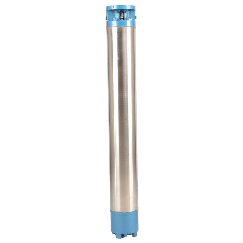
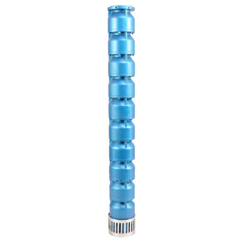
The pump parts are mainly composed of pump shaft, impeller, shunt shell, rubber bearing, check valve body (optional) and other components. The motor part is mainly composed of base, pressure regulating diaphragm, thrust bearing, thrust plate, lower guide bearing seat, stator, rotor, upper guide bearing seat, sand discharging ring, water inlet section, lead cable and other components. The motor is a water-filled submersible three-phase asynchronous motor, which is filled with water to cool the motor and lubricate the bearing. The pressure regulating diaphragm at the bottom is used to adjust the difference in internal water expansion and contraction pressure caused by the temperature rise of the motor. In order to prevent the sand in the well water from entering the motor, two oil seals are installed at the upper end of the motor shaft extension, and a sand discharging ring is installed to form a sand discharging structure. In order to prevent the pump shaft from jumping when starting, the pump shaft is connected with the motor shaft through a coupling, and a thrust bearing is installed at the lower part of the motor. The lubrication of the motor and the pump bearing is water lubrication. The stator winding of the motor adopts high quality submersible motor winding wire, with high insulation performance. The pump adopts computer CAD design, with simple structure and excellent technical performance.

(1) Przygotowanie przed instalacją:
1. Sprawdź, czy pompa głębinowa spełnia warunki użytkowania i zakres określony w instrukcji.
2. Za pomocą ciężkiego przedmiotu o średnicy równej maksymalnej średnicy zewnętrznej pompy głębinowej zmierzyć, czy średnica wewnętrzna odwiertu zmieści się w pompie głębinowej oraz zmierzyć, czy głębokość studni spełnia wymagania montażowe.
3. Sprawdź, czy odwiert jest czysty i czy woda w studni jest mętna. Nigdy nie używaj elektrycznej pompy głębinowej do mycia błota i piasku z pompy Welor, aby uniknąć przedwczesnego uszkodzenia pompy elektrycznej.
4. Sprawdź, czy pozycja zacisku montażowego głowicy spawalniczej jest odpowiednia i czy wytrzyma jakość całego urządzenia
5. Sprawdź czy elementy pompy głębinowej są kompletne i prawidłowo zamontowane zgodnie ze schematem montażu zawartym w instrukcji. Zdejmij sito filtra i obróć sprzęgło, aby sprawdzić, czy obraca się elastycznie
6. Odkręć śrubę wodną i napełnij komorę silnika czystą, niekorozyjną wodą (pamiętaj o jej napełnieniu), a następnie dokręć śrubę wodną. Po 12 godzinach wtrysku wody rezystancja izolacji silnika nie powinna być mniejsza niż 150M Q, mierzona za pomocą stołu wibracyjnego 500V.
7. Cable joint, cut off a 120mm rubber sleeve from one end of the outgoing cable and the matching cable with an electrician's knifethen stagger the length of the three core wires in a stepped shape, peel off a 20mm copper core, scrape of the oxide layer on theoutside of the copper wire with a knife or sand cloth, and insert the two connected wire ends in palirs.After tying the layer tightly with fine copper wire, solder it thoroughly and firmly, and sand of any. burrs on the surface. Then, forthe three joints, use polyvester insulation tape to wrap them in a semi stacked manner for three lavers. Wrap the two ends of thewrapping layer tightywith nyion thread,and then use a semi stacked method to wrap the tape for three layers. Wrap the outellayer with high-pressure insulation tape for three layers. Finally, fold the threestrands together and repeatedly wrap them for fivelayers with high-pressure tape. Each layer must be tightly tied, and the interlayer joints must be tight and fimm to prevent water frompenetrating and damaging the insulation, After wrapping, soak in water at room temperature of 20 ’c for 12 hours, and measurethe insulation resistance with a shaking table, which should not be less than 100M Ω
Załączony schemat procesu okablowania kabla jest następujący: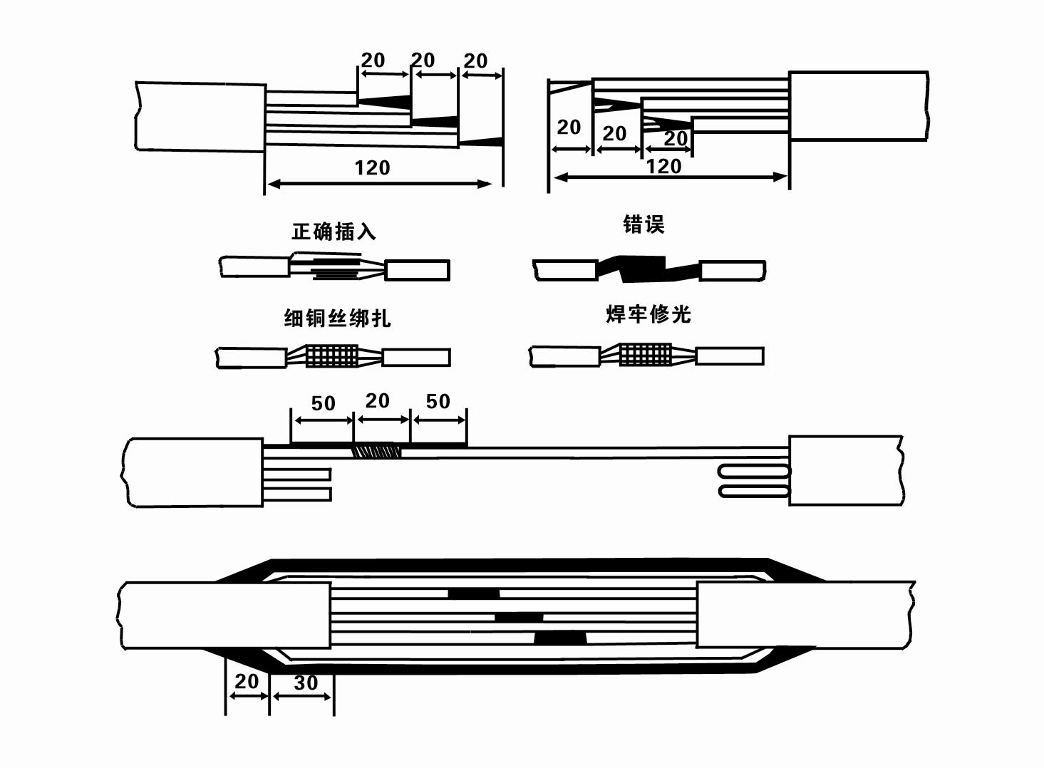
8. Za pomocą multimetru sprawdź, czy przewody trójfazowe są podłączone i czy rezystancja prądu stałego jest w przybliżeniu zrównoważona.
9. Sprawdź, czy obwód i moc transformatora nie są przeciążone, a następnie podłącz wyłącznik zabezpieczający przed przeciążeniem lub sprzęt rozruchowy. Aby zapoznać się z konkretnymi modelami, patrz Tabela 2, a następnie wlej wiadro wody do pompy wodnej z wylotu pompy wodnej, aby nasmarować gumowe łożyska pompy, a następnie umieść elektryczną pompę głębinową pionowo i stabilnie. Uruchomienie (nie dłużej niż jedna sekunda) i sprawdź, czy kierunek skrętu jest zgodny ze znakiem skrętu. Jeśli nie, zamień dowolne dwie wtyczki kabla trójfazowego. Następnie zainstaluj filtr i przygotuj się do zejścia do studni. W przypadku używania pompy elektrycznej do specjalnych celów (takich jak rowy, rowy, rzeki, stawy, stawy itp.) pompa elektryczna musi być niezawodnie uziemiona.
(2) Sprzęt i narzędzia instalacyjne:
1. Jedna para łańcuchów do podnoszenia na ponad dwie tony.
2. Statyw o wysokości pionowej nie mniejszej niż cztery metry.
3. Dwie wiszące liny (liny stalowe) o wytrzymałości większej niż jedna tona (mogą udźwignąć ciężar kompletnego zestawu pomp wodnych).
4. Zamontuj dwie pary zacisków (szyn).
5. Klucze, młotki, śrubokręty, narzędzia i przyrządy elektryczne itp.
(3) Instalacja pompy elektrycznej:
1. Schemat instalacji elektrycznej pompy głębinowej pokazano na rysunku 2. Konkretne wymiary montażowe pokazano w Tabeli 3 „Wykaz wymiarów montażowych pompy elektrycznej głębinowej”.
2. Zatapialne pompy elektryczne o wysokości podnoszenia mniejszej niż 30 metrów można wciągać bezpośrednio do studni za pomocą węży i lin stalowych lub innych lin konopnych, które są w stanie unieść cały ciężar całej maszyny, rur wodociągowych i wody w rurach.
3. W pompach o wysokości podnoszenia większej niż 30 metrów stosuje się rury stalowe, a kolejność montażu jest następująca:
①Użyj zacisku, aby zacisnąć górny koniec części pompy wodnej (silnik i pompa wodna zostały w tym czasie połączone), podnieś ją za pomocą wiszącego łańcucha i powoli przymocuj do studni, aż założysz zacisk na głowicę odwiertu i zdemontujesz wiszący łańcuch.
② Użyj kolejnej pary zacisków, aby zacisnąć rurę, podnieś ją za pomocą wiszącego łańcucha w odległości 15 cm od kołnierza i powoli opuść. Pomiędzy kołnierzem rury a kołnierzem pompy Załóż gumową podkładkę i równomiernie dokręć rurę i pompę za pomocą śrub, nakrętek i podkładek sprężystych.
③ Lekko podnieś pompę głębinową, zdejmij zacisk na górnym końcu pompy wodnej, mocno przymocuj kabel do rury wodnej za pomocą plastikowej taśmy i powoli zamocuj, aż zacisk zostanie umieszczony na głowicy odwiertu.
④Użyj tej samej metody, aby podłączyć wszystkie rury wodociągowe do studni.
⑤Po podłączeniu kabla wyjściowego do przełącznika sterującego, należy go podłączyć do trójfazowego źródła zasilania.
(4) Rzeczy, na które należy zwrócić uwagę podczas instalacji:
1. Jeśli podczas pompowania zostanie stwierdzone zjawisko zakleszczenia, obróć lub pociągnij rurę wodną, aby pokonać punkt zakleszczenia. Jeśli różne środki nadal nie pomagają, nie należy opuszczać pompy na siłę, aby uniknąć uszkodzenia elektrycznej pompy głębinowej i studni.
2. Podczas montażu należy na kołnierz każdej rury założyć podkładkę gumową i równomiernie ją dokręcić.
3. Po opuszczeniu pompy wodnej do studni należy ją umieścić na środku rury studni, aby zapobiec długotrwałemu uderzaniu pompy o ścianę studni, powodując wibrację pompy oraz zamiatanie i spalanie silnika .
4. Określ głębokość pompy wodnej do dna studni, zgodnie z warunkami przepływu piasku i mułu w studni. Nie zakopuj pompy w błocie. Odległość pompy wodnej od dna studni na ogół nie jest mniejsza niż 3 metry (patrz rysunek 2).
5. Głębokość wejścia wody do pompy wodnej nie powinna być mniejsza niż 1-1,5 metra od dynamicznego poziomu wody do węzła wlotu wody (patrz rysunek 2). W przeciwnym razie łożyska pompy wodnej mogą łatwo ulec uszkodzeniu.
6. Podnoszenie pompy wodnej nie może być zbyt niskie. W przeciwnym razie na rurociągu wody głowicy odwiertu należy zainstalować zasuwę, aby kontrolować przepływ pompy w znamionowym punkcie przepływu, aby zapobiec przeciążeniu i spaleniu silnika z powodu dużych prędkości przepływu.
7. Gdy pompa wodna pracuje, wydatek wody powinien być ciągły i równy, prąd powinien być stabilny (w znamionowych warunkach pracy, na ogół nie więcej niż 10% prądu znamionowego), nie powinno być żadnych wibracji ani hałasu. Jeśli wystąpią jakiekolwiek nieprawidłowości, należy zatrzymać maszynę, aby znaleźć przyczynę i ją wyeliminować.
8. Podczas montażu należy zwrócić uwagę na ustawienie przewodu uziemiającego silnik (patrz rysunek 2). Jeżeli rura wodna jest rurą stalową, należy ją poprowadzić od obejmy głowicy odwiertu; jeśli rura wodna jest rurą z tworzywa sztucznego, poprowadź ją od znaku uziemienia pompy elektrycznej.
- (1)With the continuous development of modern technology, submersible pumps play a crucial role in the field of pumps. After installing the submersible pump, check the insulation resistance and three-phase continuity repeatedly to ensure that there are no errors in the connection between the instrument and the starting equipment. If everything is normal, the test equipment can be started. After starting, observe whether the indication readings of each instrument are correct. If the rated voltage and current specified on the nameplate are exceeded, pay attention to observe whether the pump has any noise or vibration. If everything is normal, it can be put into operation. After the pump runs for four hours for the first time, it should be closed and the thermal insulation resistance of the motor should be tested quickly, and its value should not be less than 0.5 megaohms. After stopping the pump, restart it after five minutes to prevent the water column in the pipeline from completely reversing, resulting in the motor burning due to overcurrent. After the pump is running normally, in order to prolong its service life, it is necessary to check regularly whether the supply voltage, working current and insulation resistance are normal. If the following conditions are found, the equipment should be shut down immediately to troubleshoot. The current exceeds 20% under the rated working conditions; the dynamic water level drops to the inlet section, resulting in intermittent drainage; the submersible pump vibrates violently or makes noisy sounds; the supply voltage is lower than 340 volts; any fuse is broken; the water pipe is damaged; The thermal insulation resistance between the motor and the ground is less than 0.5 megaohm.These recommended operating procedures and safety measures ensure the safe operation of the submersible pump, prolong the service life of the equipment, and provide users with a reliable pump choice.
- (2)Unit disassembly:
- 1 untie the cable tie, remove the pipeline part, remove the wire plate.
- 2 unscrew the water release bolt, put the water in the motor chamber.
- 3 remove the filter, loose the fixing screw of the motor shaft on the coupling.
- 4 unscrew the bolt connecting the water inlet section with the motor, and separate the pump from the motor (pay attention to the unit cushion when separating, to prevent the bending of the pump shaft)
- 5 the disassembly sequence of the pump is: (see figure 1) water inlet section, impeller, diversion shell, impeller...... check valve body, when removing the impeller, use special tools to loosen the conical sleeve of the fixed impeller first, and avoid bending the pump shaft and various bumps in the disassembly process.
- 6 the disassembly process of the motor is: (see figure 1) place the motor on the platform, and remove the nut, base, shaft head lock nut, thrust plate, key, lower guide bearing seat, double head bolt from the bottom of the motor in turn. Then take out the rotor (pay attention not to damage the wire package) and finally remove the connecting section and upper guide bearing seat.
- 7 unit assembly: Before assembly, the rust and dirt of the parts should be cleaned, and the mating surfaces and fasteners should be coated with sealant. Then they should be assembled in the reverse order of disassembly (the up and down momentum of the motor shaft is about 1 mm after assembly). After assembly, the coupling should be flexible, and then the filter screen test machine.
- (3)The submersible pump should be dismantled and repaired according to Article 5 for each operation year, or less than one year, but the submersible time has reached two years, and the worn parts should be replaced.
1, wypuść wodę z komory silnika (szczególnie zimą, aby zapobiec zamarznięciu silnika) i dobrze zawiąż kabel.
2, store in an indoor room without corrosive substances and gases, with a temperature below 40 °C.
3, przy długotrwałym użytkowaniu należy zwrócić uwagę na zapobieganie rdzy pomp głębinowych.
- Wirnik
- Tuleja wału
- Gumowa tuleja wału
-
Uszczelka
01 Ujęcie wody ze studni głębinowej
02 Wysokie źródło wody
03 zaopatrzenie w wodę w górach
04 wieża wodna
05 Nawadnianie rolnictwa
06 nawadnianie ogrodu
07 ujęcie wody rzecznej
08 woda użytkowa

