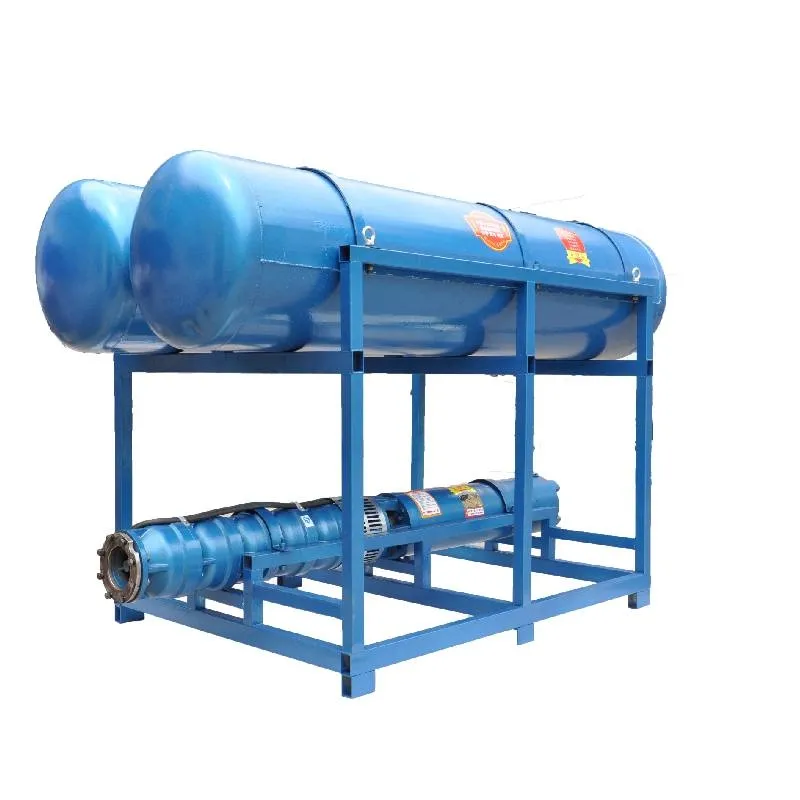
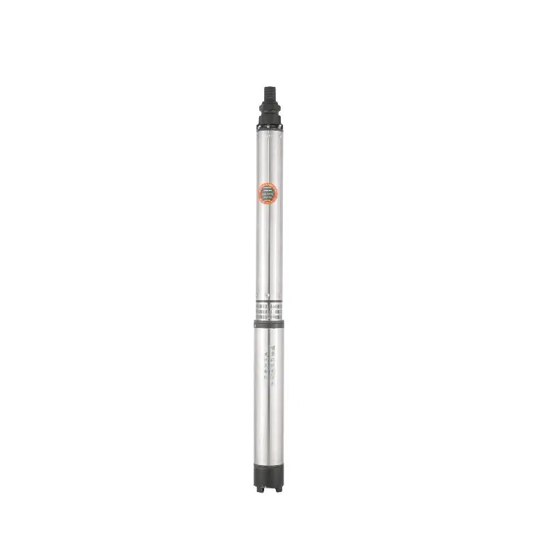
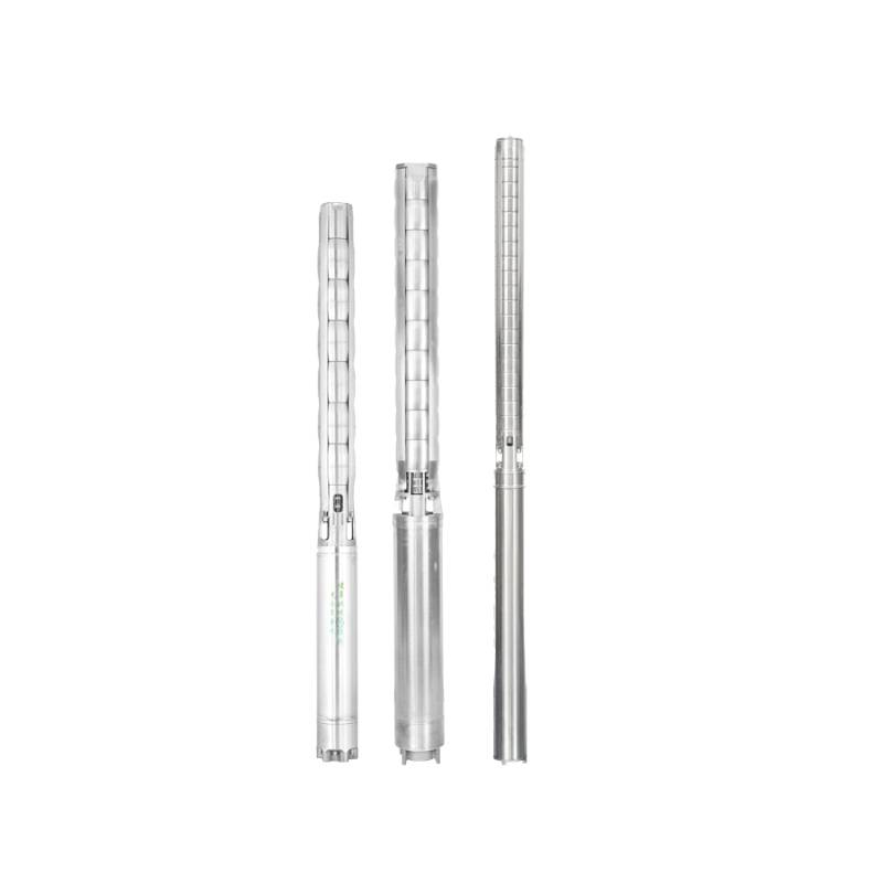
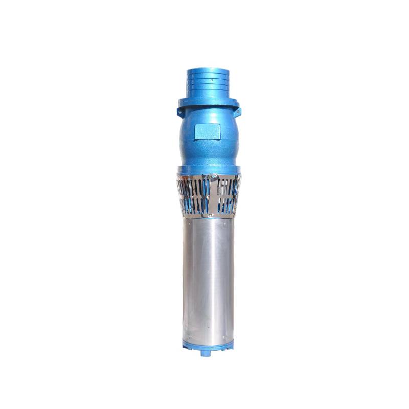
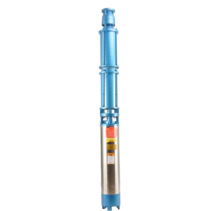
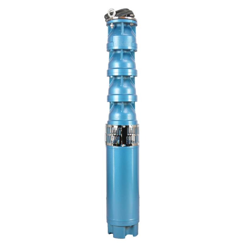
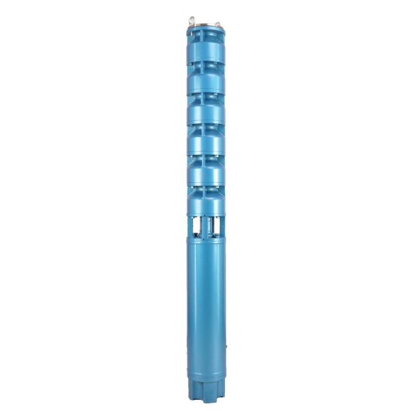
Frequency conversion winding design, ensure the motor in 1HZ-50HZ long-term stable conversion operation. Energy saving, longer service life.
1, zasilanie: trójfazowe AC 380V (tolerancja +/- 5%), 50HZ (tolerancja +/- 1%).
2, jakość wody:
(1) water temperature is not higher than 20 °C;
(2) zawartość zanieczyszczeń stałych (stosunek masowy) nie jest większa niż 0,01%;
(3) Wartość PH (pH) 6,5-8,5;
(4) zawartość siarkowodoru nie jest większa niż 1,5 mg/L;
(5) zawartość jonów chlorkowych nie jest większa niż 400 mg/l.
3, silnik jest zamknięty lub wypełniony wodą, mokra konstrukcja, przed użyciem komora silnika podwodnego musi być wypełniona czystą wodą, aby zapobiec fałszywemu napełnieniu, a następnie dokręcić wtrysk wody, śruby zwalniające powietrze, w przeciwnym razie nie wolno używać
4, pompa głębinowa musi być całkowicie zanurzona w wodzie, głębokość nurkowania nie jest większa niż 70 m, dno pompy głębinowej od dna studni jest nie mniejsze niż 3 m.
5, przepływ wody ze studni powinien być w stanie sprostać wydatku wody pompy głębinowej i ciągłej pracy, wydatek wody pompy głębinowej powinien być kontrolowany na poziomie 0,7–1,2-krotności przepływu znamionowego.
6, studnia powinna być prosta, pompa głębinowa nie może być używana ani zrzucana, tylko do użytku pionowego.
7, pompa głębinowa musi być dopasowana do kabla zgodnie z wymaganiami i zewnętrznego urządzenia zabezpieczającego przed przeciążeniem. 8, pompa jest surowo zabroniona bez maszyny do testowania obciążenia wodą
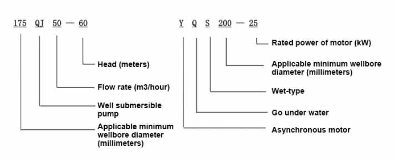
| Model | Przepływ (m3/h) | Głowa (M) |
Rotating speed(change/point) | Pompa wodna(%) | Wylot średnica (mm) |
Dobrze się sprawdza średnica (mm) |
Oceniono moc (KW) |
Rated voltage(V) | Ratedcurrent(A) | Sprawność motoryczna (%) | power factorcosφ | Jednostka Maksymalny rozmiar promieniowy (mm) |
Uwaga | |||||||||
| 125QJ5-34 | 5 | 34 | 2850 | 53 | 40 | 125powyżej | 1.5 | 380 | 4.23 | 70.0 | 0.77 | 118 | ||||||||||
| 125QJ5-51 | 51 | 2.2 | 6.03 | 72.0 | 0.77 | |||||||||||||||||
| 125QJ5-68 | 68 | 3 | 8.01 | 73.0 | 0.78 | |||||||||||||||||
| 125QJ5-85 | 85 | 4 | 10.53 | 74.0 | 0.78 | |||||||||||||||||
| 125QJ5-102 | 102 | 5.5 | 14.1 | 75.0 | 0.79 | |||||||||||||||||
| 125QJ5-119 | 119 | 5.5 | 14.1 | 75.0 | 0.79 | |||||||||||||||||
| 125QJ10-24 | 10 | 24 | 2850 | 60 | 50 | 125powyżej | 1.5 | 380 | 4.23 | 70.0 | 0.77 | 118 | ||||||||||
| 125QJ10-32 | 32 | 2.2 | 6.03 | 72.0 | 0.77 | |||||||||||||||||
| 125QJ10-48 | 48 | 3 | 8.01 | 73.0 | 0.78 | |||||||||||||||||
| 125QJ10-56 | 56 | 4 | 10.53 | 74.0 | 0.78 | |||||||||||||||||
| 125QJ10-72 | 72 | 5.5 | 14.1 | 75.0 | 0.79 | |||||||||||||||||
| 125QJ10-80 | 80 | 5.5 | 14.1 | 75.0 | 0.79 | |||||||||||||||||
| 125QJ10-104 | 104 | 7.5 | 19.0 | 76.0 | 0.79 | |||||||||||||||||
| 125QJ10-120 | 10 | 120 | 2850 | 60 | 50 | 125powyżej | 7.5 | 380 | 19.0 | 76.0 | 0.79 | 118 | ||||||||||
| 125QJ10-136 | 136 | 9.2 | 22.7 | 77.0 | 0.8 | |||||||||||||||||
| 125QJ15-36 | 15 | 36 | 2850 | 63 | 50 | 125powyżej | 2.2 | 380 | 6.03 | 72.0 | 0.77 | 118 | ||||||||||
| 125QJ15-39 | 39 | 3 | 8.01 | 73.0 | 0.78 | |||||||||||||||||
| 125QJ15-46 | 46 | 4 | 10.53 | 74.0 | 0.78 | |||||||||||||||||
| 125QJ15-52 | 52 | 4 | 10.53 | 74.0 | 0.78 | |||||||||||||||||
| 125QJ15-59 | 59 | 5.5 | 14.1 | 75.0 | 0.79 | |||||||||||||||||
| 125QJ15-65 | 65 | 5.5 | 14.1 | 75.0 | 0.79 | |||||||||||||||||
| 125QJ15-78 | 78 | 7.5 | 19.0 | 76.0 | 0.79 | |||||||||||||||||
| 125QJ15-91 | 91 | 7.5 | 19.0 | 76.0 | 0.79 | |||||||||||||||||
| 125QJ15-104 | 104 | 9.2 | 22.7 | 77.0 | 0.8 | |||||||||||||||||
| 125QJ20-16 | 20 | 16 | 2850 | 64 | 50 | 125powyżej | 2.2 | 380 | 6.03 | 72.0 | 0.77 | 118 | ||||||||||
| 125QJ20-24 | 24 | 3 | 8.01 | 73.0 | 0.78 | |||||||||||||||||
| 125QJ20-32 | 32 | 4 | 10.53 | 74.0 | 0.78 | |||||||||||||||||
| 125QJ20-40 | 40 | 4 | 10.53 | 74.0 | 0.78 | |||||||||||||||||
| 125QJ20-48 | 48 | 5.5 | 14.1 | 75.0 | 0.79 | |||||||||||||||||
| 125QJ20-56 | 56 | 5.5 | 14.1 | 75.0 | 0.79 | |||||||||||||||||
| 125QJ20-64 | 64 | 7.5 | 19.0 | 76.0 | 0.79 | |||||||||||||||||
| 125QJ20-72 | 72 | 7.5 | 19.0 | 76.0 | 0.79 | |||||||||||||||||
| 125QJ20-80 | 80 | 9.2 | 22.7 | 77.0 | 0.8 | |||||||||||||||||
| 125QJ25-12 | 25 | 12 | 2850 | 64 | 65 | 125powyżej | 2.2 | 380 | 6.03 | 72.0 | 0.77 | 118 | ||||||||||
| 125QJ25-18 | 18 | 3 | 8.01 | 73.0 | 0.78 | |||||||||||||||||
| 125QJ25-24 | 24 | 4 | 10.53 | 74.0 | 0.78 | |||||||||||||||||
| 125QJ25-30 | 30 | 4 | 10.53 | 74.0 | 0.78 | |||||||||||||||||
| 125QJ25-36 | 36 | 5.5 | 14.1 | 75.0 | 0.79 | |||||||||||||||||
| 125QJ25-48 | 48 | 7.5 | 19.0 | 76.0 | 0.79 | |||||||||||||||||
| 125QJ25-60 | 60 | 9.2 | 22.7 | 77.0 | 0.8 | |||||||||||||||||
| 125QJ32-24 | 32 | 24 | 2850 | 64 | 80 | 125powyżej | 4 | 380 | 10.53 | 74.0 | 0.78 | 118 | ||||||||||
| 125QJ32-30 | 30 | 5.5 | 14.1 | 75.0 | 0.79 | |||||||||||||||||
| 125QJ32-42 | 42 | 7.5 | 19.0 | 76.0 | 0.79 | |||||||||||||||||
| 125QJ32-54 | 54 | 9.2 | 22.7 | 77.0 | 0.8 | |||||||||||||||||
| 125QJ5-240 | 5 | 240 | 2850 | 40 | 125powyżej | 11 | 380 | 26.28 | 118 | |||||||||||||
| 125QJ5-280 | 280 | 13 | 30.87 | |||||||||||||||||||
| 125QJ5-320 | 320 | 15 | 35.62 | |||||||||||||||||||
| 125QJ10-180 | 10 | 180 | 2850 | 50 | 125powyżej | 11 | 380 | 26.28 | 118 | |||||||||||||
| 125QJ10-210 | 210 | 13 | 30.87 | |||||||||||||||||||
| 125QJ10-240 | 240 | 15 | 35.62 | |||||||||||||||||||
| 125QJ15-120 | 15 | 120 | 2850 | 50 | 125powyżej | 11 | 380 | 26.28 | 118 | |||||||||||||
| 125QJ15-142 | 142 | 13 | 30.87 | |||||||||||||||||||
| 125QJ15-162 | 162 | 15 | 35.62 | |||||||||||||||||||
| 125QJ20-100 | 20 | 100 | 2850 | 50 | 125powyżej | 11 | 380 | 26.28 | 118 | |||||||||||||
| 125QJ20-120 | 120 | 13 | 30.87 | |||||||||||||||||||
| 125QJ20-136 | 136 | 15 | 35.62 | |||||||||||||||||||
| 125QJ25-82 | 25 | 82 | 2850 | 65 | 125powyżej | 11 | 380 | 26.28 | 118 | |||||||||||||
| 125QJ25-97 | 97 | 13 | 30.87 | |||||||||||||||||||
| 125QJ25-110 | 110 | 15 | 35.62 | |||||||||||||||||||
| 125QJ32-68 | 32 | 68 | 2850 | 80 | 125powyżej | 11 | 380 | 26.28 | 118 | |||||||||||||
| 125QJ32-80 | 80 | 13 | 30.87 | |||||||||||||||||||
| 125QJ32-92 | 92 | 15 | 35.62 | |||||||||||||||||||
| 125QJ40-46 | 40 | 46 | 2850 | 80 | 125powyżej | 11 | 380 | 26.28 | 118 | |||||||||||||
| 125QJ40-54 | 54 | 13 | 30.87 | |||||||||||||||||||
| 125QJ40-62 | 62 | 15 | 35.62 | |||||||||||||||||||
The well submersible pump is a pump suitable for clear water. It is strictly prohibited to dig new wells and pump out mud and sand. The voltage grade of the well pump is 380V/50HZ, and other voltage grades of the submersible motor need to be customized. Underground cables must be waterproof cables and must be equipped with starting equipment, such as distribution box, etc. The starting equipment should have common motor comprehensive protection functions, such as short circuit overload protection, phase loss protection, undervoltage protection, grounding protection and idling protection, etc. In abnormal cases, the protective device should be tripped in time. When installing and using the pump, it must be firmly grounded. It is prohibited to push and pull the switch when the hands and feet are wet. The power supply must be cut off before installing and maintaining the pump. An obvious "anti-electric shock" sign must be set up where the pump is used. Before going down the well or installing the motor, the inner cavity must be filled with distilled water or non-corrosive clean cold water, and the water injection/drainage bolts must be tightened. Fill the pump with water for ground test to lubricate the rubber bearings. The instant start time shall not exceed one second to check whether the direction is correct and consistent with the direction indication. Be sure to pay attention to safety when placing the pump upright to prevent overturning and causing injury. Strictly in accordance with the provisions of the pump lift and flow range of use, to prevent the pump flow at low lift or excessive pull at high lift, resulting in extreme wear of thrust bearings and other components, resulting in motor overload burn. After the pump into the well, the insulation resistance between the motor and the ground shall be measured, which shall not be less than 100MΩ. After the start, observe the voltage and current regularly, and check the motor winding insulation, to see if it meets the requirements; if the pump storage temperature is below the freezing point, the water in the motor cavity should be discharged, so as to avoid the water in the motor cavity freezing and damaging the motor due to low temperature.
Główne cechy produktu to:
1.The motor is a water-loaded wet submersible three-phase asynchronous motor,and the motor cavity is filled with clean water for cooling the motor and lubricating the bearing.The regulating diaphragm at the bottom of the motor is used to adjust the expansion and contraction pressure difference inside and outside the body caused by the temperature rise of the motor.
2.In order to prevent the sand particles in the well water from entering the motor,two oil seals are installed at the extension end of the motor shaft,and the sand ring is installed to form a sand prevention structure.
3.In order to prevent the pump shaft from jumping when starting,the pump shaft is connected with the motor shaft through a coupling,and the thrust bearing is installed at the bottom of the motor.
4.The lubrication of the motor and the pump bearing is water lubrication.
5.The stator winding of the motor adopts high-quality submersible motor winding wire,with excellent insulation performance.
6.The pump is designed by computer CAD,with simple structure and excellent technical performance.

(1) Przygotowanie przed instalacją:
1. Sprawdź, czy pompa głębinowa spełnia warunki użytkowania i zakres określony w instrukcji.
2. Za pomocą ciężkiego przedmiotu o średnicy równej maksymalnej średnicy zewnętrznej pompy głębinowej zmierzyć, czy średnica wewnętrzna odwiertu zmieści się w pompie głębinowej oraz zmierzyć, czy głębokość studni spełnia wymagania montażowe.
3. Sprawdź, czy odwiert jest czysty i czy woda w studni jest mętna. Nigdy nie używaj elektrycznej pompy głębinowej do mycia błota i piasku z pompy Welor, aby uniknąć przedwczesnego uszkodzenia pompy elektrycznej.
4. Sprawdź, czy pozycja zacisku montażowego głowicy spawalniczej jest odpowiednia i czy wytrzyma jakość całego urządzenia
5. Sprawdź czy elementy pompy głębinowej są kompletne i prawidłowo zamontowane zgodnie ze schematem montażu zawartym w instrukcji. Zdejmij sito filtra i obróć sprzęgło, aby sprawdzić, czy obraca się elastycznie
6. Odkręć śrubę wodną i napełnij komorę silnika czystą, niekorozyjną wodą (pamiętaj o jej napełnieniu), a następnie dokręć śrubę wodną. Po 12 godzinach wtrysku wody rezystancja izolacji silnika nie powinna być mniejsza niż 150M Q, mierzona za pomocą stołu wibracyjnego 500V.
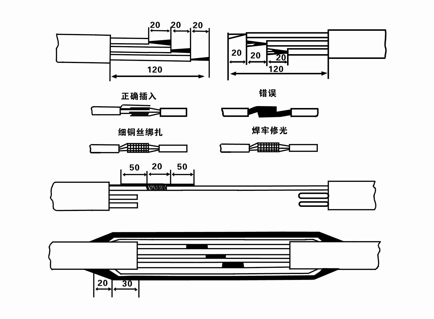
7. Cable joint, cut off a 120mm rubber sleeve from one end of the outgoing cable and the matching cable with an electrician's knifethen stagger the length of the three core wires in a stepped shape, peel off a 20mm copper core, scrape of the oxide layer on theoutside of the copper wire with a knife or sand cloth, and insert the two connected wire ends in palirs.
After tying the layer tightly with fine copper wire, solder it thoroughly and firmly, and sand of any. burrs on the surface. Then, forthe three joints, use polyvester insulation tape to wrap them in a semi stacked manner for three lavers. Wrap the two ends of thewrapping layer tightywith nyion thread,and then use a semi stacked method to wrap the tape for three layers. Wrap the outellayer with high-pressure insulation tape for three layers. Finally, fold the threestrands together and repeatedly wrap them for fivelayers with high-pressure tape. Each layer must be tightly tied, and the interlayer joints must be tight and fimm to prevent water frompenetrating and damaging the insulation, After wrapping, soak in water at room temperature of 20 ’c for 12 hours, and measurethe insulation resistance with a shaking table, which should not be less than 100M Ω
Załączony schemat procesu okablowania kabla jest następujący:
8. Za pomocą multimetru sprawdź, czy przewody trójfazowe są podłączone i czy rezystancja prądu stałego jest w przybliżeniu zrównoważona.
9. Check whether the circuit and transformer capacity are overloaded, and then connect the overload protection switch or starting equipment. See Table 2 for specific models, and then
Pour a bucket of water into the water pump from the water pump outlet to lubricate the rubber bearings in the pump, and then place the submersible electric pump upright and steady.
Start (no more than one second) and check whether the steering direction is consistent with the steering sign. If not, swap any two connectors of the three-phase cable.
Then install the filter and prepare to go down the well. If used in special occasions (such as ditches, ditches, rivers, ponds, ponds, etc.), the electric pump must be reliably grounded.
(2) Sprzęt i narzędzia instalacyjne:
1. Jedna para łańcuchów do podnoszenia na ponad dwie tony.
2. Statyw o wysokości pionowej nie mniejszej niż cztery metry.
3. Dwie wiszące liny (liny stalowe) o wytrzymałości większej niż jedna tona (mogą udźwignąć ciężar kompletnego zestawu pomp wodnych).
4. Zamontuj dwie pary zacisków (szyn).
5. Klucze, młotki, śrubokręty, narzędzia i przyrządy elektryczne itp.
(3) Instalacja pompy elektrycznej:
1. Schemat instalacji elektrycznej pompy głębinowej pokazano na rysunku 2. Konkretne wymiary montażowe pokazano w Tabeli 3 „Wykaz wymiarów montażowych pompy elektrycznej głębinowej”.
2. Zatapialne pompy elektryczne o wysokości podnoszenia mniejszej niż 30 metrów można wciągać bezpośrednio do studni za pomocą węży i lin stalowych lub innych lin konopnych, które są w stanie unieść cały ciężar całej maszyny, rur wodociągowych i wody w rurach.
3. W pompach o wysokości podnoszenia większej niż 30 metrów stosuje się rury stalowe, a kolejność montażu jest następująca:
①Use a clamp to clamp the upper end of the water pump part (the motor and water pump have been connected at this time), lift it with a hanging chain, and slowly tie it into the well until
Put the clamp on the wellhead and remove the hanging chain.
② Use another pair of clamps to clamp a pipe, lift it with a hanging chain 15 cm away from the flange, and lower it slowly. Between pipe flange and pump flange
Put the rubber pad in place and tighten the pipe and pump evenly with bolts, nuts and spring washers.
③ Lekko podnieś pompę głębinową, zdejmij zacisk na górnym końcu pompy wodnej, mocno przymocuj kabel do rury wodnej za pomocą plastikowej taśmy i powoli zamocuj, aż zacisk zostanie umieszczony na głowicy odwiertu.
④Użyj tej samej metody, aby podłączyć wszystkie rury wodociągowe do studni.
⑤Po podłączeniu kabla wyjściowego do przełącznika sterującego, należy go podłączyć do trójfazowego źródła zasilania.
(4) Rzeczy, na które należy zwrócić uwagę podczas instalacji:
1. If a jamming phenomenon is found during the pumping process, turn or pull the water pipe to overcome the jamming point. If various measures still do not work, please
Do not force the pump down to avoid damage to the submersible electric pump and the well.
2. Podczas montażu należy na kołnierz każdej rury założyć podkładkę gumową i równomiernie ją dokręcić.
3. Po opuszczeniu pompy wodnej do studni należy ją umieścić na środku rury studni, aby zapobiec długotrwałemu uderzaniu pompy o ścianę studni, powodując wibrację pompy oraz zamiatanie i spalanie silnika .
4. Określ głębokość pompy wodnej do dna studni, zgodnie z warunkami przepływu piasku i mułu w studni. Nie zakopuj pompy w błocie. Odległość pompy wodnej od dna studni na ogół nie jest mniejsza niż 3 metry (patrz rysunek 2).
5. Głębokość wejścia wody do pompy wodnej nie powinna być mniejsza niż 1-1,5 metra od dynamicznego poziomu wody do węzła wlotu wody (patrz rysunek 2). W przeciwnym razie łożyska pompy wodnej mogą łatwo ulec uszkodzeniu.
6. Podnoszenie pompy wodnej nie może być zbyt niskie. W przeciwnym razie na rurociągu wody głowicy odwiertu należy zainstalować zasuwę, aby kontrolować przepływ pompy w znamionowym punkcie przepływu, aby zapobiec przeciążeniu i spaleniu silnika z powodu dużych prędkości przepływu.
7. Gdy pompa wodna pracuje, wydatek wody powinien być ciągły i równy, prąd powinien być stabilny (w znamionowych warunkach pracy, na ogół nie więcej niż 10% prądu znamionowego), nie powinno być żadnych wibracji ani hałasu. Jeśli wystąpią jakiekolwiek nieprawidłowości, należy zatrzymać maszynę, aby znaleźć przyczynę i ją wyeliminować.
8. Podczas montażu należy zwrócić uwagę na ustawienie przewodu uziemiającego silnik (patrz rysunek 2). Jeżeli rura wodna jest rurą stalową, należy ją poprowadzić od obejmy głowicy odwiertu; jeśli rura wodna jest rurą z tworzywa sztucznego, poprowadź ją od znaku uziemienia pompy elektrycznej.
- 1. Po zamontowaniu pompy głębinowej należy ponownie sprawdzić rezystancję izolacji i przewodnictwo trójfazowe od wyłącznika, sprawdzić, czy przyrząd i podłączenie urządzeń rozruchowych są prawidłowe, jeśli nie ma problemu, można uruchomić maszynę próbną, i zaobserwuj, czy po uruchomieniu wskazania wskaźników przyrządu przekraczają napięcie i prąd znamionowy podane na tabliczce znamionowej, oraz zaobserwuj, czy w pompie występują zjawiska hałasu i wibracji, i jeśli wszystko jest w porządku, uruchom ją.
- 2. Po pierwszym uruchomieniu pompy przez cztery godziny należy wyłączyć silnik w celu szybkiego sprawdzenia rezystancji izolacji termicznej, a jej wartość nie powinna być mniejsza niż 0,5 megaoma.
- 3. Po wyłączeniu pompy należy ją uruchomić po pięciu minutach, aby zapobiec całkowitemu ponownemu wypłynięciu słupa wody w rurze, co mogłoby spowodować nadmierny prąd silnika i przepalenie.
- 4. Po uruchomieniu pompy, w celu przedłużenia jej żywotności, należy regularnie sprawdzać, czy napięcie zasilania, prąd roboczy i rezystancja izolacji są w normie. W przypadku stwierdzenia poniższych warunków należy natychmiast wyłączyć pompę w celu rozwiązania problemu.
- 1 In the rated condition, the current exceeds 20%.
- 2 Dynamiczny poziom wody spada do sekcji wlotu wody, powodując okresowe pojawianie się wody.
- 3 W pompie głębinowej występują silne wibracje lub hałas.
- 4 Napięcie zasilania jest niższe niż 340 woltów.
- 5 Przepalony bezpiecznik.
- 6 Rura doprowadzająca wodę jest uszkodzona.
- 7 The motor's thermal insulation resistance is lower than 0.5 megaohm.
- Unit disassembly:
- 1.Untie the cable tie, remove the pipeline part, and remove the wire plate.
- 2.screw down the water bolt, put the water in the motor chamber.
- 3.remove the filter, loose the fixed screw on the coupling to fix the motor shaft.
- 4.screw down the bolt connecting the water inlet section with the motor, and separate the pump from the motor (pay attention to the unit cushion when separating, to prevent the bending of the pump shaft)
- 5.the disassembly sequence of the pump is: (see figure 1) water inlet section, impeller, diversion shell, impeller...... check valve body, when removing the impeller, use special tools to loosen the conical sleeve of the fixed impeller first, and avoid bending and bruising the pump shaft in the process of disassembly.
- 6.the disassembly process of the motor is: (see figure 1) place the motor on the platform, and remove the nuts, base, shaft head locking nut, thrust plate, key, lower guide bearing seat and double head bolt from the bottom of the motor in turn, and then take out the rotor (pay attention not to damage the wire package) and finally remove the connecting section and upper guide bearing seat.
- 7.unit assembly: before assembly, the rust and dirt of the parts should be cleaned, and the mating surface and fasteners coated with sealant, and then assembled in the opposite order of disassembly (the motor shaft moves up and down after assembly for about one millimeter), after assembly, the coupling should be flexible, and then the filter screen test machine. Submersible pumps shall be taken out of the well for dismantling and maintenance according to Article 5 after a year of operation, or less than a year of operation but two years of diving time, and the worn parts shall be replaced.
This product is an efficient and durable submersible electric pump, suitable for a variety of environments and applications.In order to ensure the long-term use and stable performance of the product, we suggest that users pay special attention to drying the water in the motor cavity in winter to avoid freezing; in addition, the cable is coiled and tied, and properly stored in an environment without corrosive substances and gases, with a temperature below 40 °C. If the product is not used for a long time, attention should be paid to rust prevention treatment to ensure the life cycle and performance of the product.Whether for industrial use or for home use, this submersible electric pump can provide you with reliable pump service.
-
- Wirnik
- Tuleja wału
- Gumowa tuleja wału
-
Uszczelka
01 Ujęcie wody ze studni głębinowej
02 Wysokie źródło wody
03 zaopatrzenie w wodę w górach
04 wieża wodna
05 Nawadnianie rolnictwa
06 nawadnianie ogrodu
07 ujęcie wody rzecznej
08 woda użytkowa


