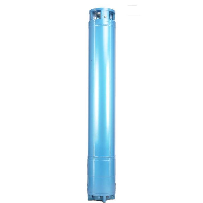
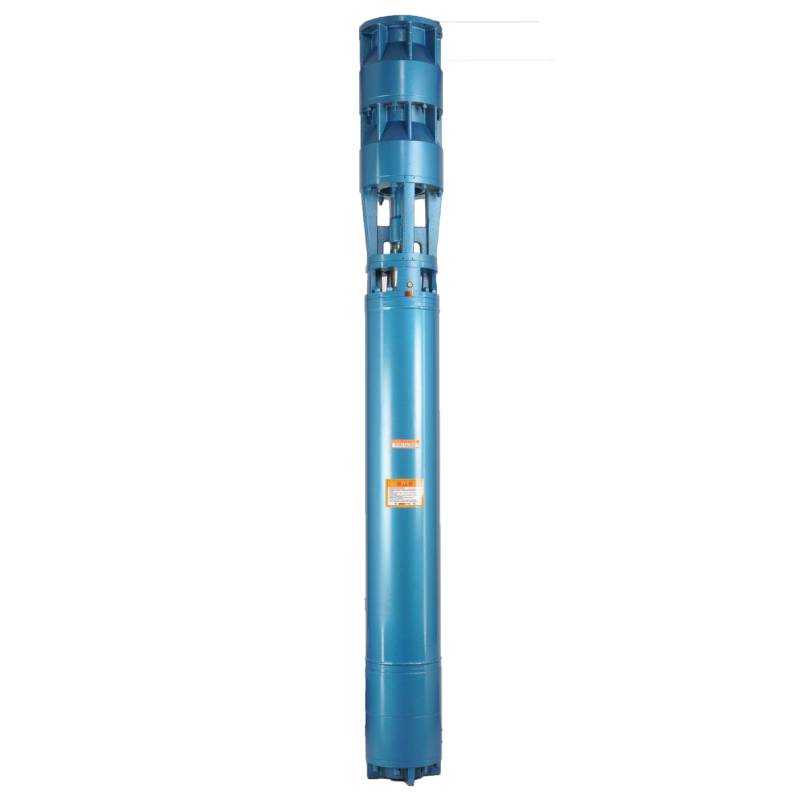
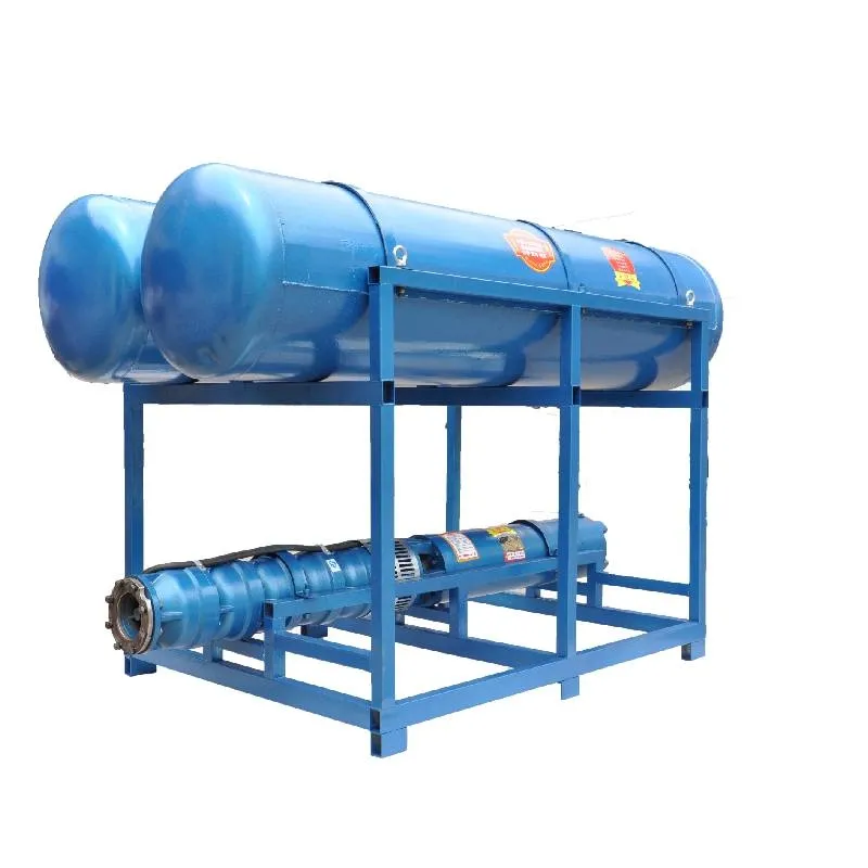
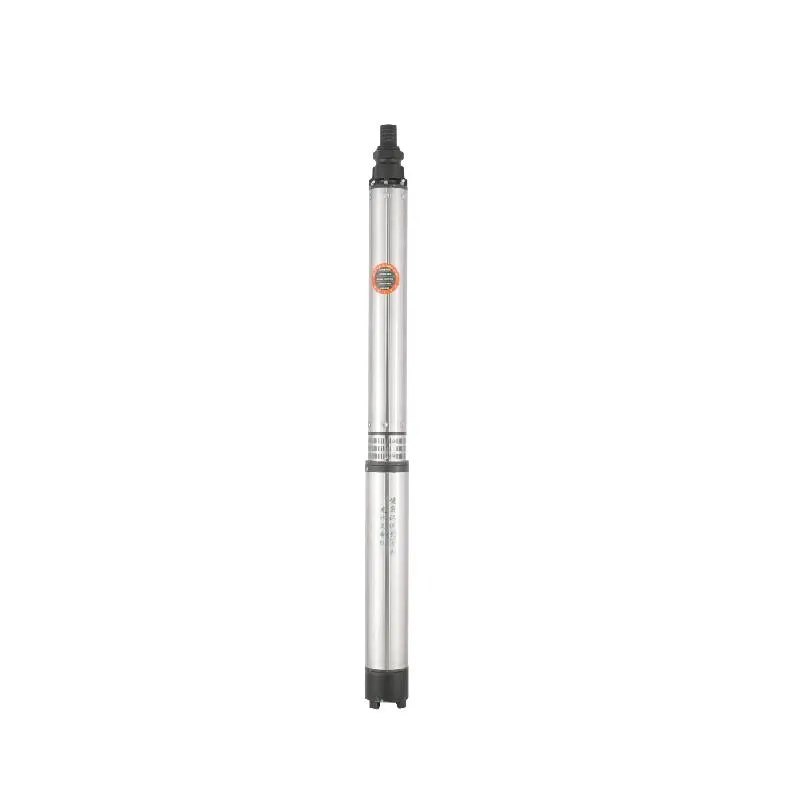
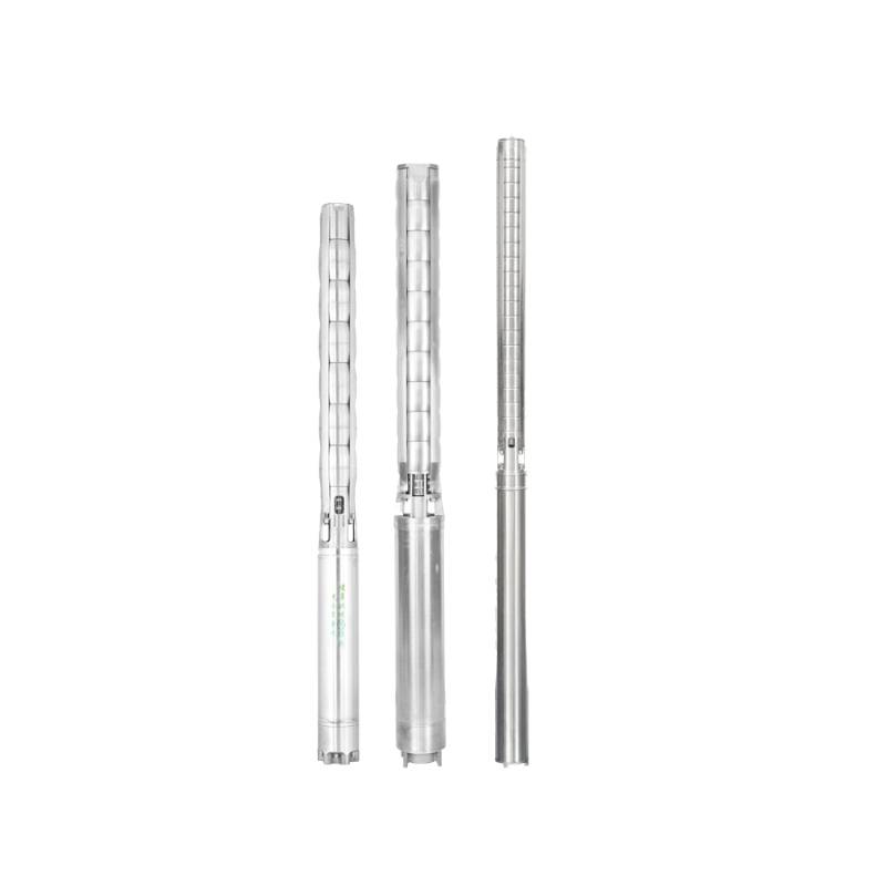
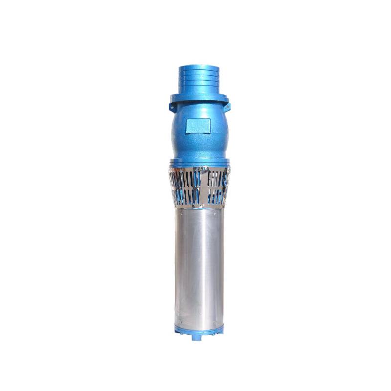
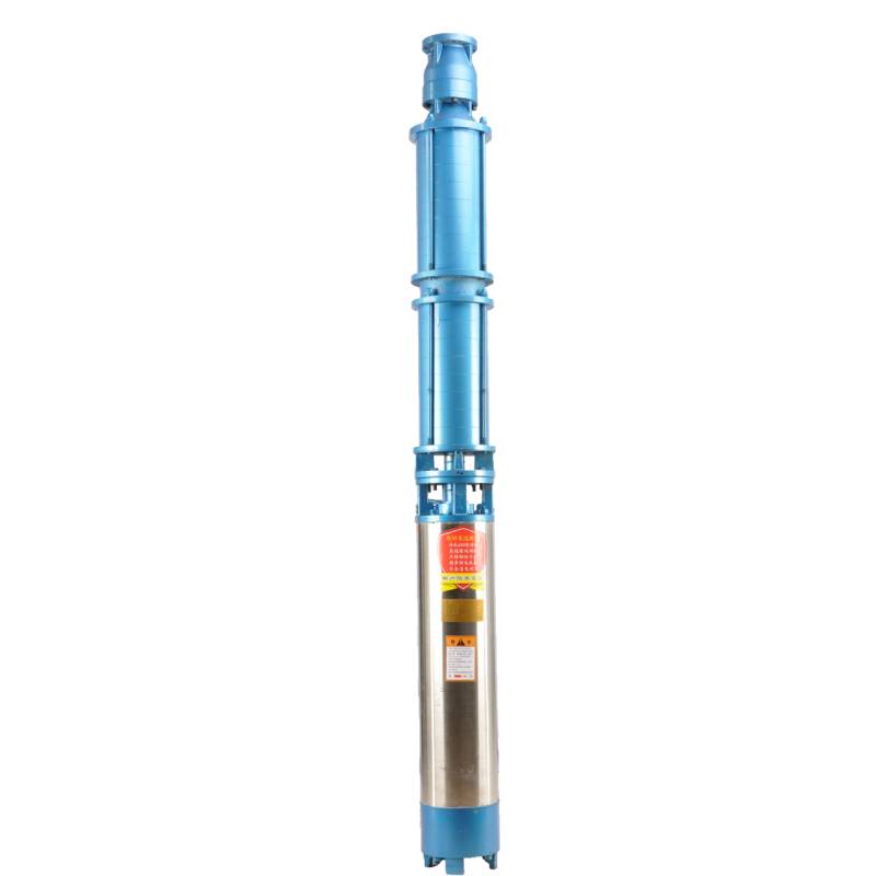
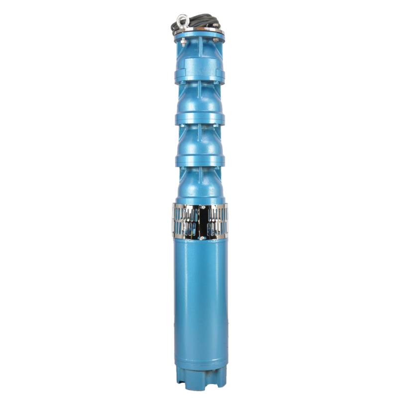
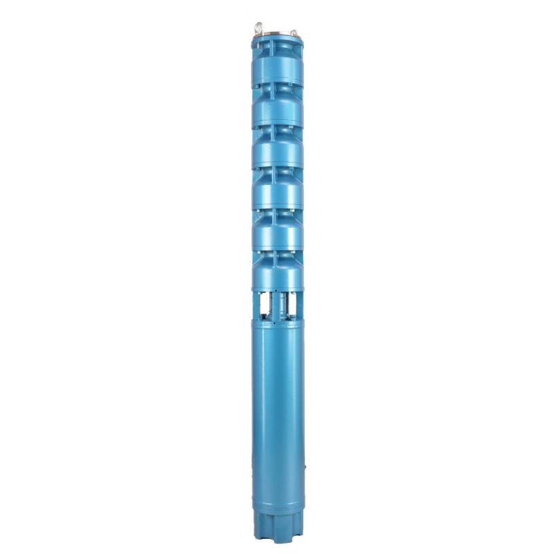
This hot water pump adopts the motor made of 50W400 grade high quality cold rolled silicon steel, which is stamped by high speed punch press. It has the advantages of low stator iron loss and low self-heating. The motor winding is designed for hot water pump, high temperature resistance and anti-aging. The winding has water resistance, and adopts 3CR13 stainless steel blade shaft, high temperature resistant bushing and other high quality accessories to enable it to operate for a long time at high temperature, and can be used with frequency converter, so as to automatically adjust according to the amount of water used. This hot water pump is the ideal choice for your hot water equipment, which can operate stably and efficiently, providing you with a lasting hot water supply.
The product is a three-phase AC 380V (tolerance + / - 5%), 50HZ (tolerance + / - 1%) power supply submersible pump. With water quality requirements: water temperature is not higher than 20 °C; solid impurities content (mass ratio) is not more than 0.01%; PH value (pH) is 6.5-8.5; hydrogen sulfide content is not more than 1.5mg/L; chloride ion content is not more than 400mg/L. The electric pump adopts closed or water sealed wet structure, before use must be submersible motor inner cavity filled with clean water to prevent empty, and then tighten the water and air bolts, otherwise not to use. Its work should be completely immersed in water, immersion depth is not more than 70 meters, the distance between the bottom of the pump and the bottom of the well is not less than 3 meters. Well water inflow quantity should be able to meet the electric pump water output and continuous operation, the output water quantity should be controlled at 0.7-1.2 times of the rated flow. The well should be vertical, the electric pump can not be used horizontally or inclined, only vertically placed. The electric pump must be equipped with cables and external overload protection device as required. It is strictly prohibited to conduct no-load test under no water condition.
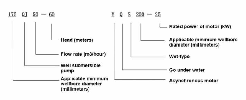
| Model | Flow (m3/h) | Hoved (m) |
Roterende hastighed (ændring/punkt) |
Vandpumpe(%) | Udtag diameter (mm) |
Velegnet diameter (mm) |
Bedømt power(KW) |
Bedømt spænding (V) |
Bedømt strøm(A) |
Motoreffektivitet (%) | power factorcosφ | Enhed Radial maksimal størrelse (mm) |
Bemærkning | |||||||||
| 300QJ200-40 | 200 | 40 | 2900 | 76 | 150 | 300over | 37 | 380 | 77.8 | 85.0 | 0.85 | 281 | ||||||||||
| 300QJ200-60 | 60 | 55 | 115 | 85.5 | 0.85 | |||||||||||||||||
| 300QJ200-80 | 80 | 75 | 154.1 | 86.0 | 0.86 | |||||||||||||||||
| 300QJ200-100 | 100 | 90 | 183.8 | 86.5 | 0.86 | |||||||||||||||||
| 300QJ200-120 | 120 | 100 | 204.3 | 86.5 | 0.86 | |||||||||||||||||
| 300QJ200-140 | 140 | 125 | 249.5 | 87.5 | 0.87 | |||||||||||||||||
| 300QJ200-160 | 160 | 140 | 277.8 | 88.0 | 0.87 | |||||||||||||||||
| 300QJ200-180 | 180 | 160 | 317.5 | 88.0 | 0.87 | |||||||||||||||||
| 300QJ200-200 | 200 | 185 | 367.2 | 88.0 | 0.87 | |||||||||||||||||
| 300QJ200-240 | 240 | 220 | 436.6 | 88.0 | 0.87 | |||||||||||||||||
| 300QJ320-30 | 320 | 30 | 2900 | 77 | 200 | 300over | 45 | 380 | 94.6 | 85.0 | 0.85 | 281 | ||||||||||
| 300QJ320-60 | 60 | 90 | 183.8 | 86.5 | 0.86 | |||||||||||||||||
| 300QJ320-90 | 90 | 125 | 249.5 | 87.5 | 0.87 | |||||||||||||||||
| 300QJ320-120 | 120 | 160 | 317.5 | 88.0 | 0.87 | |||||||||||||||||
1, well submersible pump for clean water pump, prohibit the new well, pumping sediment and muddy water,
2, well water pump voltage grade of 380/50HZ, the use of other voltage grades of submersible motors need to be customized. The underground cable must use waterproof cable, must be equipped with starting equipment, such as distribution box, start not ready should have commonly used motor comprehensive protection function, such as short circuit overload protection, phase protection, undervoltage protection, grounding protection, idling protection, in case of abnormal conditions, the protection device should be timely action trip.
3, the installation and use of the pump must be reliably grounded, prohibit the push and pull switch when the hands and feet are wet, the installation and maintenance of the pump must be cut off the power supply, the use of the pump place to set up "to prevent electric shock" obvious signs:
4, down the well or before installation, the motor cavity must be filled with distilled water or non-corrosive clean cold boiling water, tighten the / water bolt, the pump on the ground test run, must be to the pump chamber water lubrication rubber bearings, instant start not more than a second, see whether the steering is the same as the steering instructions. When the pump is upright, pay attention to safety, prevent overturning injury.
5, strengt i henhold til bestemmelserne i pumpeløftet, flowets anvendelsesområde, for at forhindre lavt flow eller høj løft pumpekraft, tryklejet og andre dele af slid, motoren overbelastning brændt
6, efter pumpen ned i brønden, bør målingen af motoren til jordens isoleringsmodstand ikke være mindre end 100M, efter starten for at observere spændingen og strømmen, skal du kontrollere motorviklingsisoleringen, uanset om den er i overensstemmelse med kravene; pumpe opbevaringssted temperatur, hvis mindre end frysepunktet, bør være tørt vandet i motorhulrummet, forhindre motorhulrummet vand isskader forårsaget af lav temperatur.
The pump part is mainly composed of pump shaft, impeller, shunt shell, rubber bearing, check valve body (optional) and other components. The motor part is mainly composed of base, pressure regulating diaphragm, thrust bearing, thrust plate, lower guide bearing seat, stator, rotor, upper guide bearing seat, sand discharging ring, water inlet section, lead cable and other components. The main characteristic of this product is that the motor is a water-cooled submersible three-phase asynchronous motor, and the motor cavity is filled with water to cool the motor and lubricate the bearing. The pressure regulating diaphragm at the bottom is used to adjust the expansion-contraction pressure difference in the body caused by the change of the temperature rise of the motor. In order to prevent the sand particles in the well water from entering the motor, two oil seals are installed at the upper end of the motor shaft extension, and a sand discharging ring is installed to form a sand discharging structure. In order to prevent the pump shaft from jumping when starting, the pump shaft and the motor shaft are connected together through a coupling, and a thrust bearing is installed at the bottom of the motor. The lubrication of the motor and the pump bearing is realized through water lubrication. The stator winding of the motor is made of high-quality well motor winding wire, with high insulation performance. The pump is designed by computer CAD, with simple structure and good technical performance.

(1) Forberedelse før installation:
1. Kontroller, om dykpumpen opfylder de brugsbetingelser og omfang, der er specificeret i manualen.
2. Brug en tung genstand med en diameter svarende til den maksimale ydre diameter af dykpumpen, mål om brøndboringens indvendige diameter kan passe til dykpumpen, og mål om brønddybden opfylder installationskravene.
3. Tjek om brøndboringen er ren, og om brøndvandet er grumset. Brug aldrig en elektrisk dykpumpe til at vaske welorpumpens mudder og sandvand for at undgå for tidlig beskadigelse af den elektriske dykpumpe.
4. Kontroller, om placeringen af brøndhovedinstallationsklemmen er passende, og om den kan modstå hele enhedens kvalitet
5. Tjek om dykpumpens komponenter er komplette og installeret korrekt i henhold til monteringsdiagrammet i manualen Fjern filterskærmen og drej koblingen for at se om den roterer fleksibelt
6. Skru vandskruen af og fyld motorhulrummet med rent, ikke-ætsende vand (bemærk. sørg for at fylde det op), og spænd derefter vandskruen. Efter 12 timers vandindsprøjtning bør motorens isolationsmodstand ikke være mindre end 150M Q målt med et 500V rystebord.
7. Cable joint, cut off a 120mm rubber sleeve from one end of the outgoing cable and the matching cable with an electrician's knifethen stagger the length of the three core wires in a stepped shape, peel off a 20mm copper core, scrape of the oxide layer on theoutside of the copper wire with a knife or sand cloth, and insert the two connected wire ends in palirs.After tying the layer tightly with fine copper wire, solder it thoroughly and firmly, and sand of any. burrs on the surface. Then, forthe three joints, use polyvester insulation tape to wrap them in a semi stacked manner for three lavers. Wrap the two ends of thewrapping layer tightywith nyion thread,and then use a semi stacked method to wrap the tape for three layers. Wrap the outellayer with high-pressure insulation tape for three layers. Finally, fold the threestrands together and repeatedly wrap them for fivelayers with high-pressure tape. Each layer must be tightly tied, and the interlayer joints must be tight and fimm to prevent water frompenetrating and damaging the insulation, After wrapping, soak in water at room temperature of 20 ’c for 12 hours, and measurethe insulation resistance with a shaking table, which should not be less than 100M Ω
Det vedhæftede kabelledningsdiagram er som følger: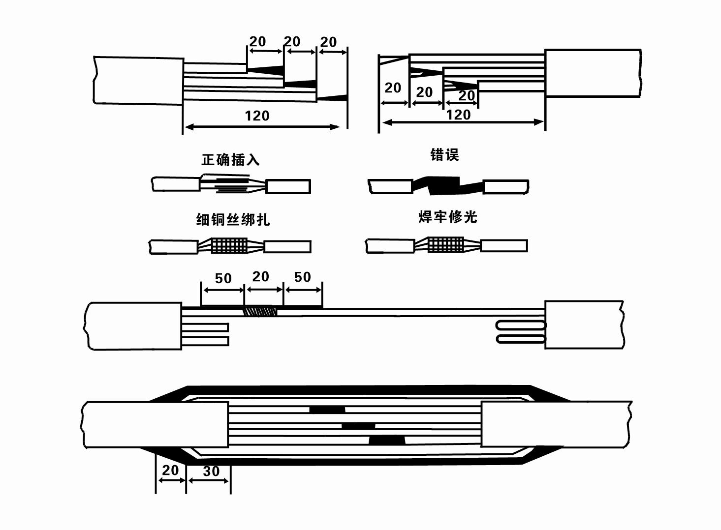
8. Brug et multimeter til at kontrollere, om de trefasede ledninger er tilsluttet, og om DC-modstanden er tilnærmelsesvis afbalanceret.
9. Kontroller, om kredsløbs- og transformatorkapaciteten er overbelastet, og tilslut derefter overbelastningsbeskyttelsesafbryderen eller startudstyret. Se tabel 2 for specifikke modeller, og hæld derefter en spand vand i vandpumpen fra vandpumpens udløb for at smøre gummilejerne i pumpen, og placer derefter den elektriske dykpumpe oprejst og stabilt. Start (ikke mere end et sekund) og kontroller, om styreretningen stemmer overens med styretegnet. Hvis ikke, så skift to vilkårlige stik på trefasekablet. Installer derefter filteret og forbered dig på at gå ned i brønden. Hvis den bruges til særlige lejligheder (såsom grøfter, grøfter, floder, damme, damme osv.), skal den elektriske pumpe være pålideligt jordet.
(2) Installationsudstyr og værktøjer:
1. Et par løftekæder til mere end to tons.
2. Et stativ med en lodret højde på ikke mindre end fire meter.
3. To hængereb (wirereb), der kan bære en vægt på mere end et ton (kan bære vægten af et komplet sæt vandpumper).
4. Installer to par klemmer (skinne).
5. Skruenøgler, hamre, skruetrækkere, elektrisk værktøj og instrumenter mv.
(3) Installation af elektrisk pumpe:
1. Installationsdiagrammet for den dyk-elektriske pumpe er vist i figur 2. De specifikke installationsdimensioner er vist i Tabel 3 "Liste over installationsdimensioner for den dyk-elektriske pumpe".
2. Dykpumper med en løftehøjde på mindre end 30 meter kan hejses direkte ned i brønden ved hjælp af slanger og ståltove eller andre hamperove, der kan bære den fulde vægt af hele maskinen, vandrør og vand i rørene.
3. Pumper med en løftehøjde på mere end 30 meter anvender stålrør, og installationsrækkefølgen er som følger:
①Brug en klemme til at klemme den øvre ende af vandpumpedelen (motoren og vandpumpen er blevet forbundet på dette tidspunkt), løft den med en hængende kæde, og bind den langsomt ind i brønden, indtil Sæt klemmen på brøndhovedet og fjern hængende kæde.
② Brug endnu et par klemmer til at klemme et rør, løft det med en hængende kæde 15 cm væk fra flangen, og sænk det langsomt. Mellem rørflange og pumpeflange Sæt gummipuden på plads og spænd røret og pumpen jævnt med bolte, møtrikker og fjederskiver.
③ Løft dykpumpen lidt, fjern klemmen på den øverste ende af vandpumpen, bind kablet fast til vandrøret med et plastikbånd, og bind det langsomt ned, indtil klemmen er placeret ved brøndhovedet.
④Brug samme metode til at binde alle vandrør i brønden.
⑤ Efter at udløbskablet er tilsluttet kontrolkontakten, tilsluttes det til den trefasede strømforsyning.
(4) Ting at bemærke under installationen:
1. Hvis der konstateres et blokeringsfænomen under pumpningsprocessen, skal du dreje eller trække i vandrøret for at overvinde blokeringspunktet. Hvis forskellige foranstaltninger stadig ikke virker, bedes du ikke tvinge pumpen ned for at undgå beskadigelse af den elektriske dykpumpe og brønden.
2. Under installationen skal der placeres en gummipude ved flangen på hvert rør og strammes jævnt.
3. Når vandpumpen sænkes ned i brønden, skal den placeres i midten af brøndrøret for at forhindre pumpen i at køre mod brøndvæggen i lang tid, hvilket får pumpen til at vibrere og motoren til at feje og brænde .
4. Bestem dybden af vandpumpen til bunden af brønden i henhold til brøndens flydende sand- og siltforhold. Begrav ikke pumpen i mudderet. Afstanden fra vandpumpen til bunden af brønden er generelt ikke mindre end 3 meter (se figur 2).
5. Vandpumpens vandindgangsdybde bør ikke være mindre end 1-1,5 meter fra den dynamiske vandstand til vandindløbsknuden (se figur 2). Ellers kan vandpumpens lejer let blive beskadiget.
6. Vandpumpens løft må ikke være for lavt. Ellers skal der installeres en skydeventil på brøndhovedets vandrørledning for at styre pumpeflowet ved det nominelle flowpunkt for at forhindre, at motoren bliver overbelastet og brændt ud på grund af store flowhastigheder.
7. Når vandpumpen kører, skal vandudgangen være kontinuerlig og jævn, strømmen skal være stabil (under nominelle arbejdsforhold, generelt ikke mere end 10% af nominel strøm), og der bør ikke være vibrationer eller støj. Hvis der er noget unormalt, skal maskinen standses for at finde ud af årsagen og eliminere den.
8. Når du installerer, skal du være opmærksom på indstillingen af motorens jordledning (se figur 2). Når vandrøret er et stålrør, før det fra brøndhovedklemmen; når vandrøret er et plastikrør, før det fra jordingsmærket på den elektriske pumpe.
After installation of the underwater pump, it is necessary to recheck the insulation resistance and three-phase continuity of the switch, and check whether the connection between the instrument and the starting equipment is wrong. If there is no problem, you can start the test machine. After starting, observe whether the indication reading of each instrument is correct. If the rated voltage and current specified on the nameplate are exceeded, observe whether the pump has any noise or vibration. If everything is normal, it can be put into operation. Four hours after the first operation of the pump, it should be turned off and the thermal insulation resistance of the motor should be quickly tested, and its value should not be less than 0.5 megaohm. After stopping the pump, it should be restarted after an interval of five minutes to prevent the water column in the pipeline from completely reversing, resulting in the motor burning due to excessive current. After the pump is put into normal operation, in order to prolong its service life, it is necessary to check regularly whether the supply voltage, working current and insulation resistance are normal. If the following conditions are found, the machine should be stopped immediately to eliminate the fault:
1 the current exceeds 20% under the rated working condition.
2 the dynamic water level drops to the inlet section, resulting in intermittent drainage.
3 the underwater pump vibrates violently or emits huge noise.
4 the supply voltage is lower than 340 volts.
5 a fuse is burned.
6 the water pipe is damaged.
7 the thermal insulation resistance of the motor to the ground is less than 0.5 megaohm.
When disassembling the device, it is necessary to untie the cable bundle and remove the pipeline part and the line protection plate. Remove the drain bolt and exclude all water in the motor chamber. Remove the filter element and loosen the screw on the coupling fixed to the motor shaft. Unscrew the bolt connecting the water inlet section and the motor, and separate the pump and the motor (pay attention to placing the device horizontally when separating to prevent the bending of the pump shaft). The sequence of disassembling the pump is as follows: (see Figure 1) water inlet section, impeller, water inlet shell, impeller. Check the valve body, and use a special tool to loosen the cone sleeve fixed to the impeller when removing the impeller. In the process of disassembly, avoid bending the pump shaft and damaging various components. The disassembly process of the motor is as follows: (see Figure 1) put the motor on the platform, and remove the nuts on the screw (pull rod bolt), base, shaft head lock nut, thrust plate, key and lower guide rail - bearing seat, bolt, and then remove the rotor (be careful not to damage the wiring harness), and finally remove the connecting parts and upper guide bearing seat. Unit assembly: before assembly, the rust and dirt of each component should be cleaned, and the sealant should be coated on each mating surface and fastener, and then assembled in the opposite order of disassembly (the movement of the motor shaft after assembly is about one millimeter), after the assembly is completed, the coupling should be flexibly rotated, and then the filter element should be placed for testing. Each time the underwater electric pump has been used for one year, or less than one year but has been immersed for two years, it must be disassembled and inspected in accordance with Article 5 and replace the worn parts.
1, læg vandet ud i motorhulrummet (især om vinteren for at forhindre, at motoren fryser), og bind kablet godt.
2, store in an indoor room without corrosive substances and gases, with a temperature below 40 °C.
3, langvarig brug skal være opmærksom på rustforebyggelse af dykpumper.
- Løbehjul
- Skaftbøsning
- Skaftbøsning af gummi
-
Pakning
01 Dyb brønds vandindtag
02 Vandforsyning i højhuse
03 bjergvandforsyning
04 tårnvand
05 Landbrugsvanding
06 havevanding
07 flodvandindtag
08 brugsvand

