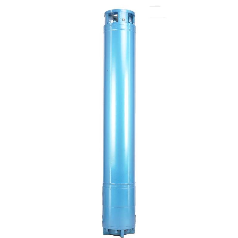
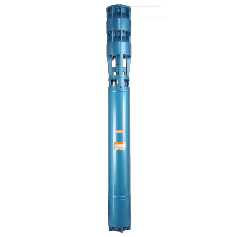
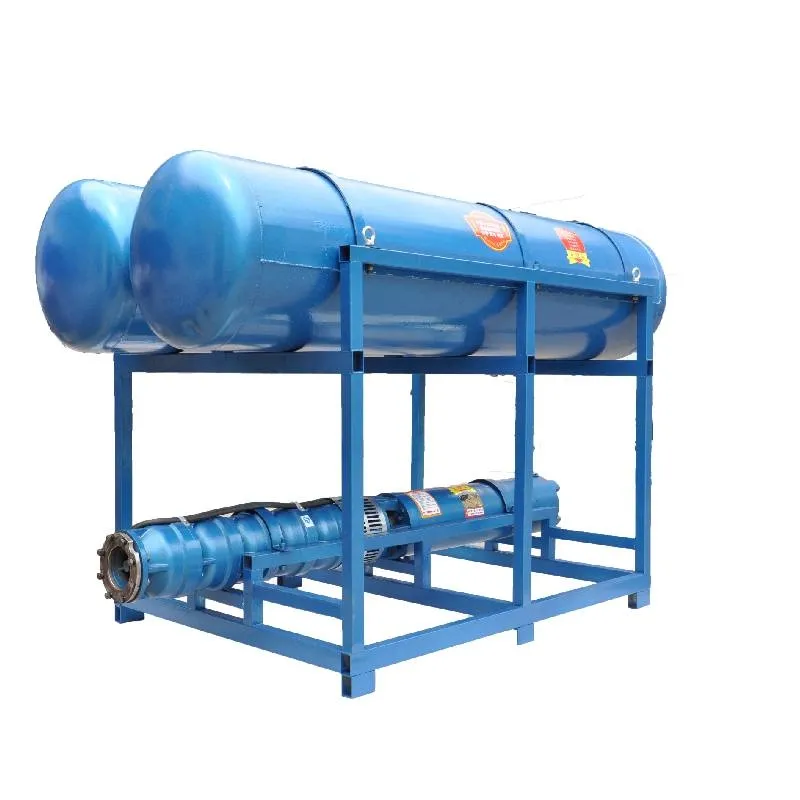
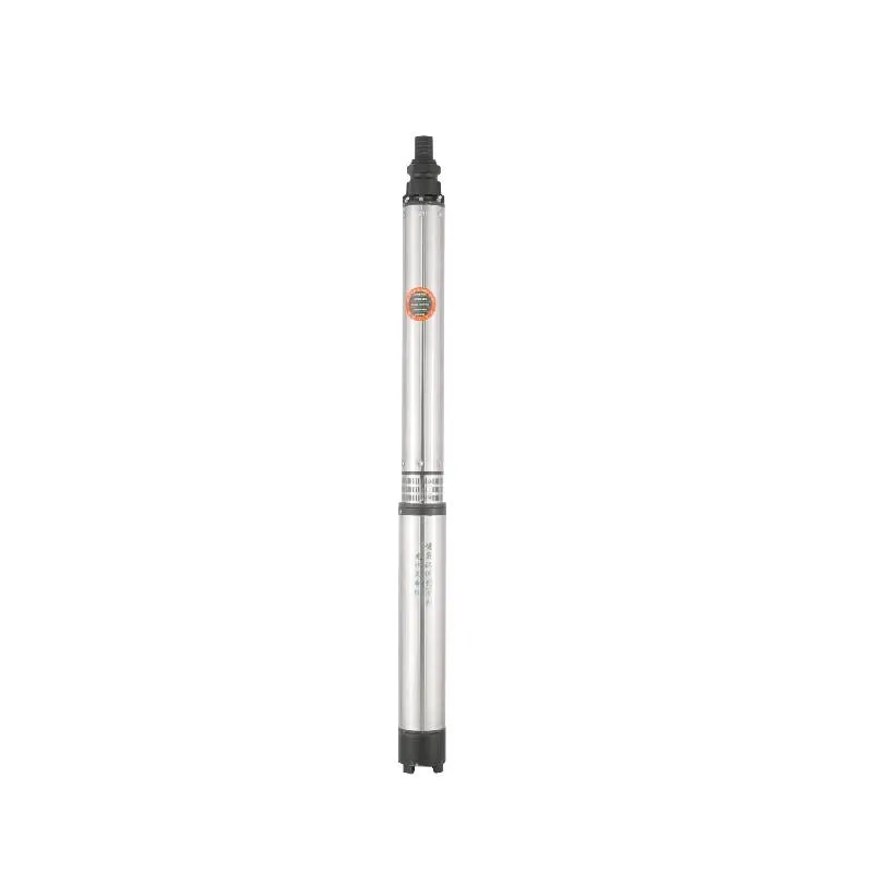
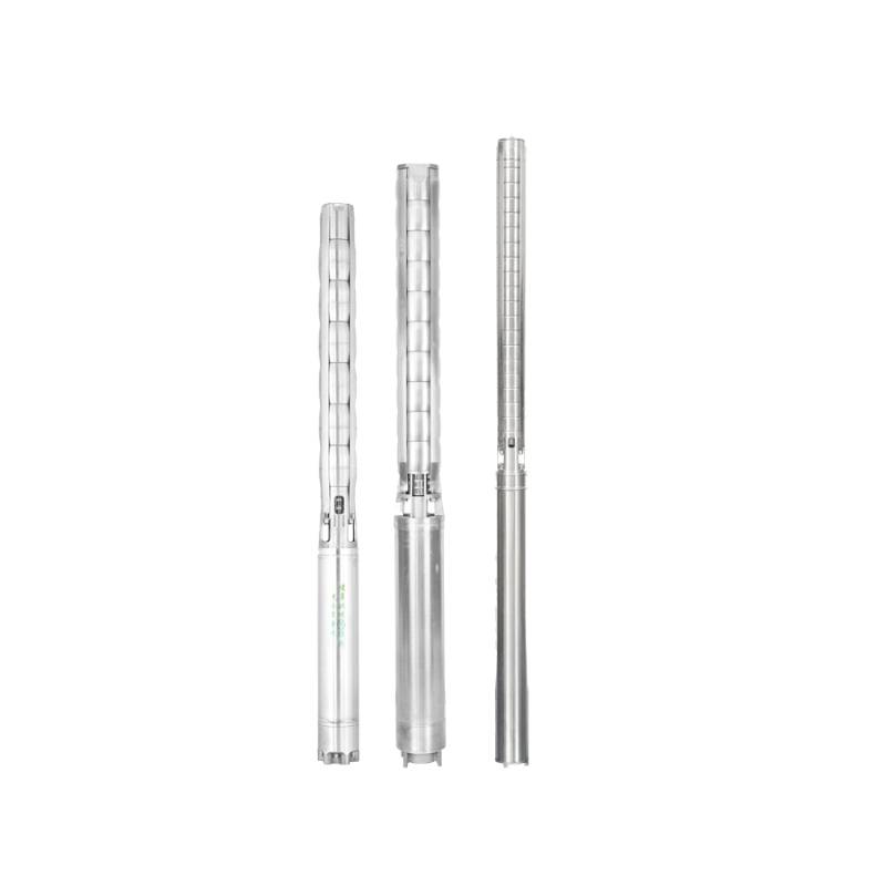
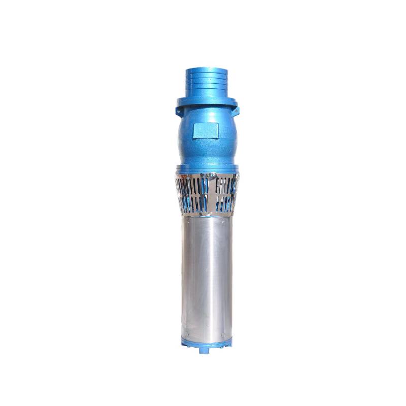
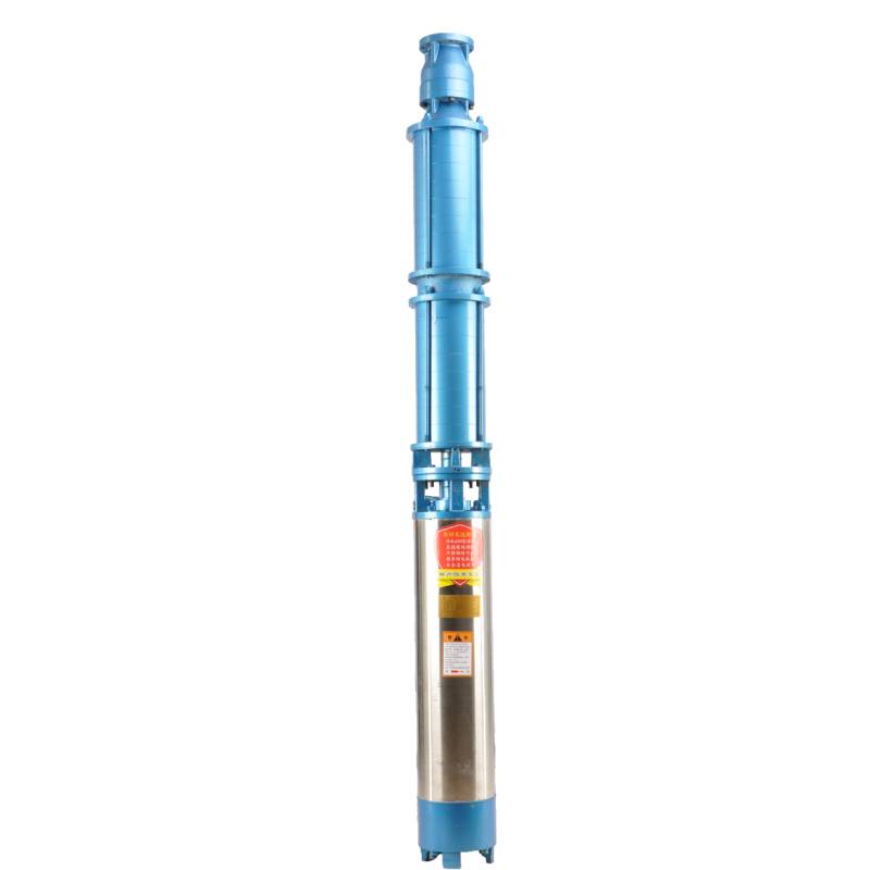
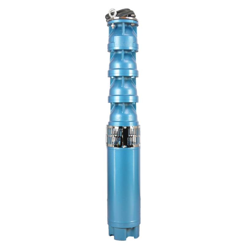
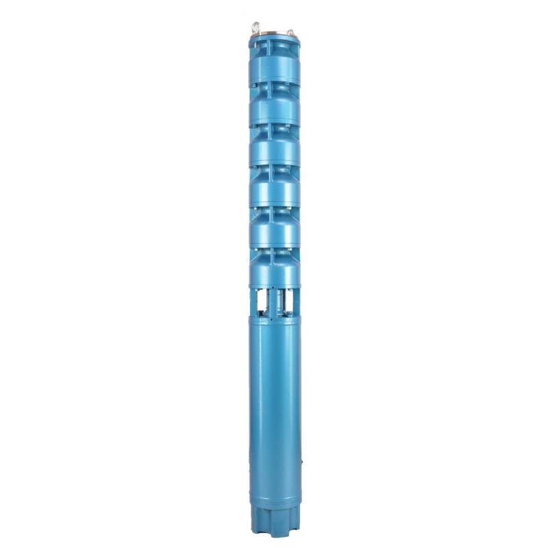
This hot water pump adopts the motor made of 50W400 grade high quality cold rolled silicon steel, which is stamped by high speed punch press. It has the advantages of low stator iron loss and low self-heating. The motor winding is designed for hot water pump, high temperature resistance and anti-aging. The winding has water resistance, and adopts 3CR13 stainless steel blade shaft, high temperature resistant bushing and other high quality accessories to enable it to operate for a long time at high temperature, and can be used with frequency converter, so as to automatically adjust according to the amount of water used. This hot water pump is the ideal choice for your hot water equipment, which can operate stably and efficiently, providing you with a lasting hot water supply.
The product is a three-phase AC 380V (tolerance + / - 5%), 50HZ (tolerance + / - 1%) power supply submersible pump. With water quality requirements: water temperature is not higher than 20 °C; solid impurities content (mass ratio) is not more than 0.01%; PH value (pH) is 6.5-8.5; hydrogen sulfide content is not more than 1.5mg/L; chloride ion content is not more than 400mg/L. The electric pump adopts closed or water sealed wet structure, before use must be submersible motor inner cavity filled with clean water to prevent empty, and then tighten the water and air bolts, otherwise not to use. Its work should be completely immersed in water, immersion depth is not more than 70 meters, the distance between the bottom of the pump and the bottom of the well is not less than 3 meters. Well water inflow quantity should be able to meet the electric pump water output and continuous operation, the output water quantity should be controlled at 0.7-1.2 times of the rated flow. The well should be vertical, the electric pump can not be used horizontally or inclined, only vertically placed. The electric pump must be equipped with cables and external overload protection device as required. It is strictly prohibited to conduct no-load test under no water condition.
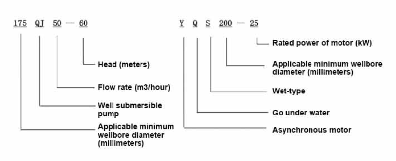
| Eredua | Emaria (m3/h) | Burua (m) |
Biraketa-abiadura (aldaketa/puntua) |
Ur-ponpa (%) | Saltokia diametroa (mm) |
Ondo aplikatzekoa diametroa (mm) |
Baloratua power(KW) |
Baloratua tentsioa (V) |
Baloratua korrontea (A) |
Motor-eraginkortasuna (%) | power factorcosφ | Unitatea Gehienezko tamaina erradiala (mm) |
Oharra | |||||||||
| 300QJ200-40 | 200 | 40 | 2900 | 76 | 150 | 300goian | 37 | 380 | 77.8 | 85.0 | 0.85 | 281 | ||||||||||
| 300QJ200-60 | 60 | 55 | 115 | 85.5 | 0.85 | |||||||||||||||||
| 300QJ200-80 | 80 | 75 | 154.1 | 86.0 | 0.86 | |||||||||||||||||
| 300QJ200-100 | 100 | 90 | 183.8 | 86.5 | 0.86 | |||||||||||||||||
| 300QJ200-120 | 120 | 100 | 204.3 | 86.5 | 0.86 | |||||||||||||||||
| 300QJ200-140 | 140 | 125 | 249.5 | 87.5 | 0.87 | |||||||||||||||||
| 300QJ200-160 | 160 | 140 | 277.8 | 88.0 | 0.87 | |||||||||||||||||
| 300QJ200-180 | 180 | 160 | 317.5 | 88.0 | 0.87 | |||||||||||||||||
| 300QJ200-200 | 200 | 185 | 367.2 | 88.0 | 0.87 | |||||||||||||||||
| 300QJ200-240 | 240 | 220 | 436.6 | 88.0 | 0.87 | |||||||||||||||||
| 300QJ320-30 | 320 | 30 | 2900 | 77 | 200 | 300goian | 45 | 380 | 94.6 | 85.0 | 0.85 | 281 | ||||||||||
| 300QJ320-60 | 60 | 90 | 183.8 | 86.5 | 0.86 | |||||||||||||||||
| 300QJ320-90 | 90 | 125 | 249.5 | 87.5 | 0.87 | |||||||||||||||||
| 300QJ320-120 | 120 | 160 | 317.5 | 88.0 | 0.87 | |||||||||||||||||
1, well submersible pump for clean water pump, prohibit the new well, pumping sediment and muddy water,
2, well water pump voltage grade of 380/50HZ, the use of other voltage grades of submersible motors need to be customized. The underground cable must use waterproof cable, must be equipped with starting equipment, such as distribution box, start not ready should have commonly used motor comprehensive protection function, such as short circuit overload protection, phase protection, undervoltage protection, grounding protection, idling protection, in case of abnormal conditions, the protection device should be timely action trip.
3, the installation and use of the pump must be reliably grounded, prohibit the push and pull switch when the hands and feet are wet, the installation and maintenance of the pump must be cut off the power supply, the use of the pump place to set up "to prevent electric shock" obvious signs:
4, down the well or before installation, the motor cavity must be filled with distilled water or non-corrosive clean cold boiling water, tighten the / water bolt, the pump on the ground test run, must be to the pump chamber water lubrication rubber bearings, instant start not more than a second, see whether the steering is the same as the steering instructions. When the pump is upright, pay attention to safety, prevent overturning injury.
5, ponpa-igogailuaren xedapenen arabera, erabilera-emariaren erabilera-eremuaren arabera, fluxu baxua edo igoera handiko ponpaketa-indarra, bultzada-errodamenduak eta higaduraren beste atal batzuk, motorren gainkarga erretzea saihesteko.
6, putzuan ponpatu ondoren, lurraren isolamendu-erresistentzia motorraren neurketa ez da 100M baino txikiagoa izan behar, tentsioa eta korrontea behatzeko hasi ondoren, egiaztatu motor harilaren isolamendua, eskakizunekin bat datorren ala ez; ponpa biltegiratze kokapena tenperatura izozte-puntua baino txikiagoa bada, motor barrunbean ura lehortu behar da, saihestu motor barrunbean ur izotza tenperatura baxuak eragindako kalteak.
The pump part is mainly composed of pump shaft, impeller, shunt shell, rubber bearing, check valve body (optional) and other components. The motor part is mainly composed of base, pressure regulating diaphragm, thrust bearing, thrust plate, lower guide bearing seat, stator, rotor, upper guide bearing seat, sand discharging ring, water inlet section, lead cable and other components. The main characteristic of this product is that the motor is a water-cooled submersible three-phase asynchronous motor, and the motor cavity is filled with water to cool the motor and lubricate the bearing. The pressure regulating diaphragm at the bottom is used to adjust the expansion-contraction pressure difference in the body caused by the change of the temperature rise of the motor. In order to prevent the sand particles in the well water from entering the motor, two oil seals are installed at the upper end of the motor shaft extension, and a sand discharging ring is installed to form a sand discharging structure. In order to prevent the pump shaft from jumping when starting, the pump shaft and the motor shaft are connected together through a coupling, and a thrust bearing is installed at the bottom of the motor. The lubrication of the motor and the pump bearing is realized through water lubrication. The stator winding of the motor is made of high-quality well motor winding wire, with high insulation performance. The pump is designed by computer CAD, with simple structure and good technical performance.

(1) Instalazio aurretik prestatzea:
1. Egiaztatu urpeko ponpak eskuliburuan zehaztutako erabilera-baldintzak eta esparruak betetzen dituen ala ez.
2. Urpeko ponparen kanpoko diametroaren gehienezko diametroa duen objektu astun bat erabiliz, neurtu putzuaren barneko diametroa ponpa urperagarrira egoki daitekeen, eta neurtu putzuaren sakonerak instalazio-baldintzak betetzen dituen.
3. Egiaztatu putzua garbi dagoen eta putzuko ura uhera den. Inoiz ez erabili urpeko ponpa elektrikorik welor pump lokatza eta harea ura garbitzeko, ponpa elektriko urperagarriari kalte goiztiarra ekiditeko.
4. Egiaztatu welhead instalazioaren posizioa egokia den eta unitate osoaren kalitatea jasan dezakeen ala ez.
5. Egiaztatu urpeko ponpa osagaiak osatuta dauden eta behar bezala instalatuta dauden eskuliburuko muntaketa-diagramaren arabera. Kendu iragazkia pantaila eta biratu akoplamendua malgutasunez biratzen duen ikusteko.
6. Askatu ur-torlojua eta bete motorraren barrunbea ur garbi eta ez korrosiboarekin (kontuan izan. ziurtatu bete egin duzula), eta estutu ur-torlojua. Ura injektatu 12 ordu igaro ondoren, motorraren isolamendu-erresistentzia ez da 150 M Q baino txikiagoa izan behar 500 V-ko astindu-mahai batekin neurtuta.
7. Cable joint, cut off a 120mm rubber sleeve from one end of the outgoing cable and the matching cable with an electrician's knifethen stagger the length of the three core wires in a stepped shape, peel off a 20mm copper core, scrape of the oxide layer on theoutside of the copper wire with a knife or sand cloth, and insert the two connected wire ends in palirs.After tying the layer tightly with fine copper wire, solder it thoroughly and firmly, and sand of any. burrs on the surface. Then, forthe three joints, use polyvester insulation tape to wrap them in a semi stacked manner for three lavers. Wrap the two ends of thewrapping layer tightywith nyion thread,and then use a semi stacked method to wrap the tape for three layers. Wrap the outellayer with high-pressure insulation tape for three layers. Finally, fold the threestrands together and repeatedly wrap them for fivelayers with high-pressure tape. Each layer must be tightly tied, and the interlayer joints must be tight and fimm to prevent water frompenetrating and damaging the insulation, After wrapping, soak in water at room temperature of 20 ’c for 12 hours, and measurethe insulation resistance with a shaking table, which should not be less than 100M Ω
Erantsitako kablearen kableatu-prozesuaren diagrama hau da: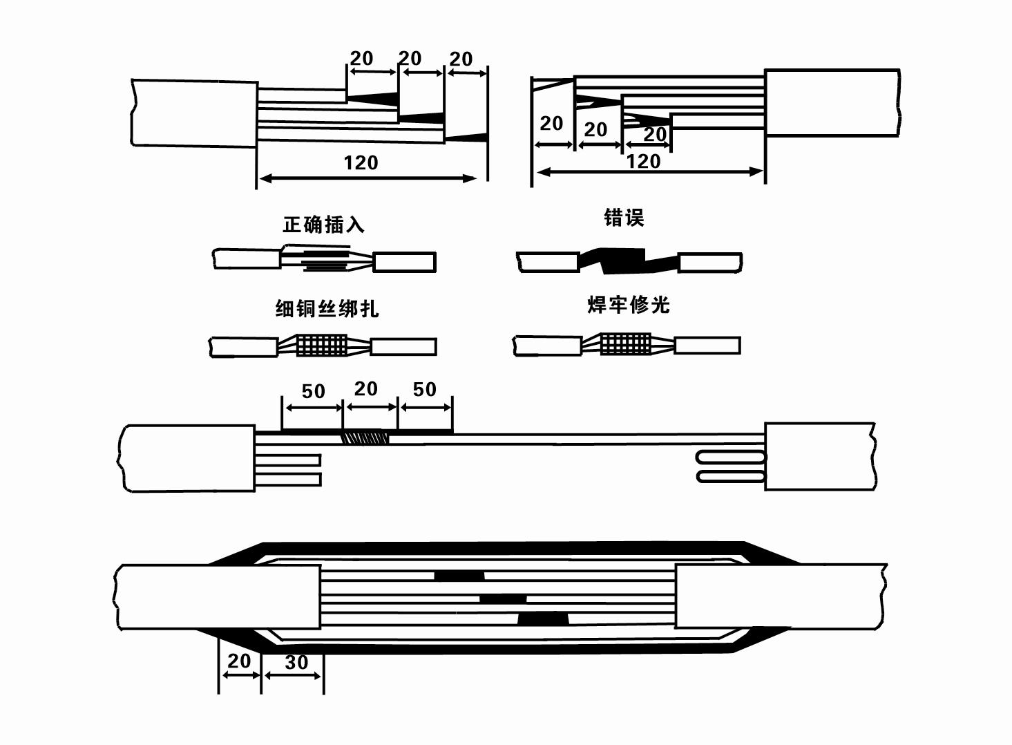
8. Erabili multimetroa hari trifasikoak konektatuta dauden eta DC erresistentzia gutxi gorabehera orekatuta dagoen egiaztatzeko.
9. Egiaztatu zirkuitua eta transformadorearen ahalmena gainkargatuta dauden ala ez, eta gero konektatu gainkarga babesteko etengailua edo abiarazte-ekipoa. Ikusi 2. taula eredu zehatzetarako, eta, ondoren, isuri ur-ontzi bat ur-ponparen irteeratik ponparen gomazko errodamenduak lubrifikatzeko, eta jarri urpeko ponpa elektrikoa zutik eta egonkor. Hasi (segundo bat baino gehiago). eta egiaztatu direkzio-norabidea koherentea den direkzio-seinalearekin. Hala ez bada, aldatu kable trifasikoko bi konektoreak. Ondoren, instalatu iragazkia eta prestatu putzutik jaisteko. Kasu berezietan erabiltzen bada (adibidez, lubakiak, lubakiak, ibaiak, urmaelak, urmaelak, etab.), ponpa elektrikoa fidagarritasunez lurreratu behar da.
(2) Instalazio ekipoak eta tresnak:
1. Bi tona baino gehiagoko altxatze-kate pare bat.
2. Lau metrotik beherako altuera bertikala duen tripode bat.
3. Tona bat baino gehiagoko pisua jasan dezaketen bi soka zintzilik (alanbrezko sokak) (ur-ponpa multzo oso baten pisua jasan dezakete).
4. Jarri bi besarkada pare (ferulak).
5. Giltzak, mailuak, bihurkinak, erreminta eta tresna elektrikoak, etab.
(3) Ponpa elektrikoaren instalazioa:
1. Urpeko ponpa elektrikoaren instalazio-diagrama 2. Irudian ageri da. Instalazio-neurri espezifikoak 3. Taulan agertzen dira "Sumergigarriko ponpa elektrikoaren instalazio-neurrien zerrenda".
2. 30 metrotik beherako burua duten ponpa elektriko urperagarriak zuzenean putzura igo daitezke, makina osoaren, ur-hodien eta hodietako uraren pisu osoa jasan dezaketen mahukak eta alanbre-sokak edo beste kalamu-soka batzuk erabiliz.
3. 30 metro baino gehiagoko burua duten ponpek altzairuzko hodiak erabiltzen dituzte, eta instalazioaren sekuentzia hau da:
①Erabili besarkada bat ur-ponparen zatiaren goiko muturra estutzeko (motorea eta ur-ponpa konektatuta daude momentu honetan), altxa ezazu zintzilik dagoen kate batekin eta lotu poliki-poliki putzuan. Jarri besarkada putzu-buruan eta kendu zintzilik katea.
② Erabili beste besarkada pare bat hodi bat estutzeko, altxa ezazu zintzilik dagoen kate batekin bridatik 15 cm-ra, eta jaitsi poliki-poliki. Hodiaren bridenaren eta ponparen bridenaren artean. Jarri gomazko kupoia eta estutu hodia eta ponpatu uniformeki torlojuekin, azkoinekin eta malguki-zirrindarekin.
③ Altxatu urpeko ponpa apur bat, kendu ur-ponparen goiko muturrean dagoen besarkada, lotu kablea tinko ur-hodiari plastikozko zinta batekin eta lotu poliki-poliki besarkada putzu-buruan jarri arte.
④Erabili metodo bera ur-hodi guztiak putzuan lotzeko.
⑤ Irteerako kablea kontrol-etengailura konektatu ondoren, elikadura trifasikora konektatzen da.
(4) Instalazioan kontuan izan beharrekoak:
1. Ponpatze-prozesuan blokeo-fenomeno bat aurkitzen bada, bira eman edo tira ur-hodiari traba-puntua gainditzeko. Hainbat neurrik oraindik ez badute funtzionatzen, mesedez, ez behartu ponpa behera urpean dagoen ponpa elektrikoa eta putzua ez kaltetzeko.
2. Instalazioan, gomazko kuskulina bat jarri behar da hodi bakoitzaren bridan eta uniformeki estutu.
3. Ur-ponpa putzuan jaisten denean, putzuaren erdian jarri behar da ponpa putzuaren hormaren kontra denbora luzez ibil ez dadin, ponpa dardara eta motorra miaketa eta erretzea eraginez. .
4. Zehaztu ur-ponparen sakonera putzuaren hondoraino, putzuaren harea eta limo-baldintzen arabera. Ez lurperatu ponpa lokatzetan. Ur-ponpatik putzuaren hondorainoko distantzia, oro har, ez da 3 metro baino gutxiagokoa (ikus 2. irudia).
5. Ur ponparen ura sartzeko sakonera ez da 1-1,5 metro baino txikiagoa izan behar uraren maila dinamikotik uraren sarrerako nodoraino (ikus 2. irudia). Bestela, ur ponparen errodamenduak erraz honda daitezke.
6. Ur-ponparen igoera ezin da baxuegia izan. Bestela, ate-balbula bat instalatu behar da putzu-buruko ur-hodietan ponparen emaria kontrolatzeko emari-puntuan emari handien ondorioz motorra gainkargatu eta erre ez dadin.
7. Ur-ponpa martxan dagoenean, ur-irteera etengabea eta berdina izan behar da, korrontea egonkorra izan behar da (lan-baldintzetan, oro har, korronte nominalaren % 10 baino gehiago), eta ez da bibraziorik edo zaratarik egon behar. Anormaltasunik badago, makina gelditu egin behar da kausa ezagutzeko eta ezabatzeko.
8. Instalatzerakoan, arreta jarri motorra lurreratzeko kablearen ezarpenari (ikus 2. irudia). Ur-hodia altzairuzko hodia denean, eraman ezazu putzu-buruko besarkadatik; ur-hodia plastikozko hodia denean, eraman ezazu ponpa elektrikoaren lurreratze-markatik.
After installation of the underwater pump, it is necessary to recheck the insulation resistance and three-phase continuity of the switch, and check whether the connection between the instrument and the starting equipment is wrong. If there is no problem, you can start the test machine. After starting, observe whether the indication reading of each instrument is correct. If the rated voltage and current specified on the nameplate are exceeded, observe whether the pump has any noise or vibration. If everything is normal, it can be put into operation. Four hours after the first operation of the pump, it should be turned off and the thermal insulation resistance of the motor should be quickly tested, and its value should not be less than 0.5 megaohm. After stopping the pump, it should be restarted after an interval of five minutes to prevent the water column in the pipeline from completely reversing, resulting in the motor burning due to excessive current. After the pump is put into normal operation, in order to prolong its service life, it is necessary to check regularly whether the supply voltage, working current and insulation resistance are normal. If the following conditions are found, the machine should be stopped immediately to eliminate the fault:
1 the current exceeds 20% under the rated working condition.
2 the dynamic water level drops to the inlet section, resulting in intermittent drainage.
3 the underwater pump vibrates violently or emits huge noise.
4 the supply voltage is lower than 340 volts.
5 a fuse is burned.
6 the water pipe is damaged.
7 the thermal insulation resistance of the motor to the ground is less than 0.5 megaohm.
When disassembling the device, it is necessary to untie the cable bundle and remove the pipeline part and the line protection plate. Remove the drain bolt and exclude all water in the motor chamber. Remove the filter element and loosen the screw on the coupling fixed to the motor shaft. Unscrew the bolt connecting the water inlet section and the motor, and separate the pump and the motor (pay attention to placing the device horizontally when separating to prevent the bending of the pump shaft). The sequence of disassembling the pump is as follows: (see Figure 1) water inlet section, impeller, water inlet shell, impeller. Check the valve body, and use a special tool to loosen the cone sleeve fixed to the impeller when removing the impeller. In the process of disassembly, avoid bending the pump shaft and damaging various components. The disassembly process of the motor is as follows: (see Figure 1) put the motor on the platform, and remove the nuts on the screw (pull rod bolt), base, shaft head lock nut, thrust plate, key and lower guide rail - bearing seat, bolt, and then remove the rotor (be careful not to damage the wiring harness), and finally remove the connecting parts and upper guide bearing seat. Unit assembly: before assembly, the rust and dirt of each component should be cleaned, and the sealant should be coated on each mating surface and fastener, and then assembled in the opposite order of disassembly (the movement of the motor shaft after assembly is about one millimeter), after the assembly is completed, the coupling should be flexibly rotated, and then the filter element should be placed for testing. Each time the underwater electric pump has been used for one year, or less than one year but has been immersed for two years, it must be disassembled and inspected in accordance with Article 5 and replace the worn parts.
1, jarri ura motorraren barrunbean (batez ere neguan, motorra izoztea saihesteko), eta lotu kablea ondo.
2, store in an indoor room without corrosive substances and gases, with a temperature below 40 °C.
3, epe luzerako erabilera ponpa urperagarrien herdoilaren prebentzioari arreta jarri behar zaio.
- Buldagailua
- Ardatz mahuka
- Gomazko ardatzaren mahuka
-
Zigilatzeko eraztuna
01 Putzu sakoneko ura hartzea
02 Goiko ur-hornidura
03 mendiko ur hornidura
04 dorre ura
05 Nekazaritzako ureztatzea
06 lorategiko ureztatzea
07 ibaiko ur-hartunea
08 etxeko ura

