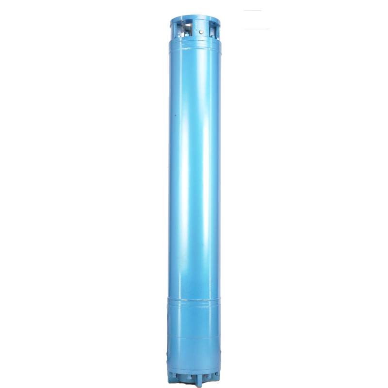
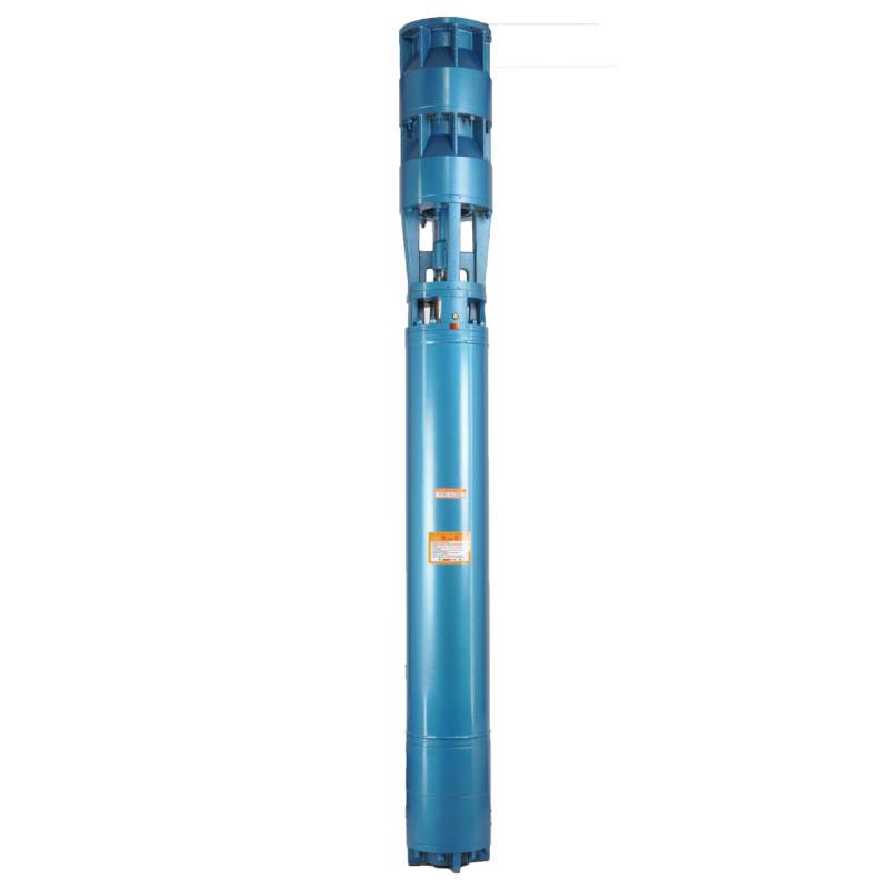
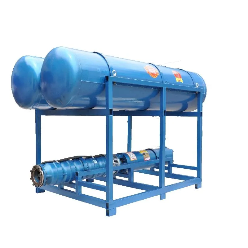
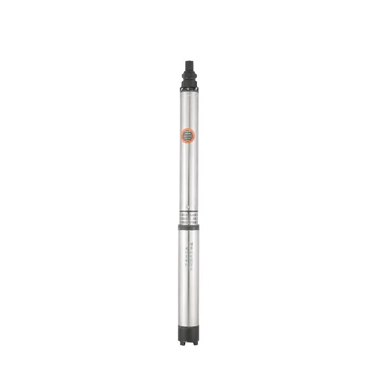
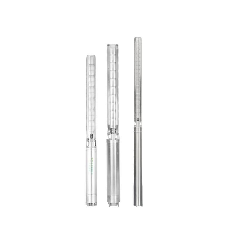
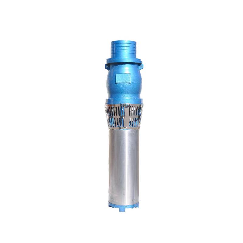
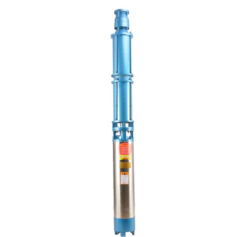
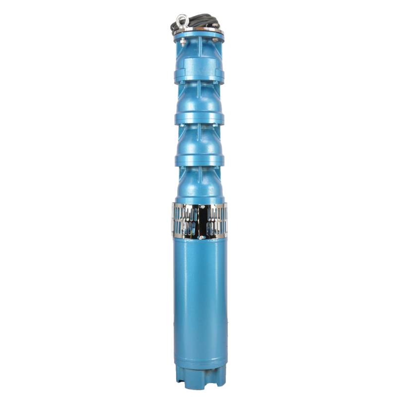
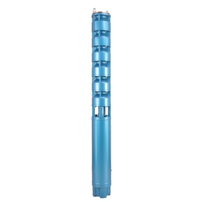
This hot water pump adopts the motor made of 50W400 grade high quality cold rolled silicon steel, which is stamped by high speed punch press. It has the advantages of low stator iron loss and low self-heating. The motor winding is designed for hot water pump, high temperature resistance and anti-aging. The winding has water resistance, and adopts 3CR13 stainless steel blade shaft, high temperature resistant bushing and other high quality accessories to enable it to operate for a long time at high temperature, and can be used with frequency converter, so as to automatically adjust according to the amount of water used. This hot water pump is the ideal choice for your hot water equipment, which can operate stably and efficiently, providing you with a lasting hot water supply.
The product is a three-phase AC 380V (tolerance + / - 5%), 50HZ (tolerance + / - 1%) power supply submersible pump. With water quality requirements: water temperature is not higher than 20 °C; solid impurities content (mass ratio) is not more than 0.01%; PH value (pH) is 6.5-8.5; hydrogen sulfide content is not more than 1.5mg/L; chloride ion content is not more than 400mg/L. The electric pump adopts closed or water sealed wet structure, before use must be submersible motor inner cavity filled with clean water to prevent empty, and then tighten the water and air bolts, otherwise not to use. Its work should be completely immersed in water, immersion depth is not more than 70 meters, the distance between the bottom of the pump and the bottom of the well is not less than 3 meters. Well water inflow quantity should be able to meet the electric pump water output and continuous operation, the output water quantity should be controlled at 0.7-1.2 times of the rated flow. The well should be vertical, the electric pump can not be used horizontally or inclined, only vertically placed. The electric pump must be equipped with cables and external overload protection device as required. It is strictly prohibited to conduct no-load test under no water condition.
| Modelo | Fluo (m3/h) | Kapo (m) |
Rotacia rapido (ŝanĝo/punkto) |
Akvopumpilo(%) | Elirejo diametro (mm) |
Aplika bone diametro (mm) |
Taksita power(KW) |
Taksita tensio (V) |
Taksita aktuala (A) |
Motorefikeco (%) | power factorcosφ | Unuo Radiala Maksimuma grandeco (mm) |
Rimarko | |||||||||
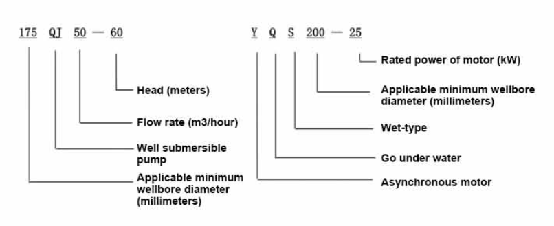
| 300QJ200-40 | 200 | 40 | 2900 | 76 | 150 | 300supre | 37 | 380 | 77.8 | 85.0 | 0.85 | 281 | ||||||||||
| 300QJ200-60 | 60 | 55 | 115 | 85.5 | 0.85 | |||||||||||||||||
| 300QJ200-80 | 80 | 75 | 154.1 | 86.0 | 0.86 | |||||||||||||||||
| 300QJ200-100 | 100 | 90 | 183.8 | 86.5 | 0.86 | |||||||||||||||||
| 300QJ200-120 | 120 | 100 | 204.3 | 86.5 | 0.86 | |||||||||||||||||
| 300QJ200-140 | 140 | 125 | 249.5 | 87.5 | 0.87 | |||||||||||||||||
| 300QJ200-160 | 160 | 140 | 277.8 | 88.0 | 0.87 | |||||||||||||||||
| 300QJ200-180 | 180 | 160 | 317.5 | 88.0 | 0.87 | |||||||||||||||||
| 300QJ200-200 | 200 | 185 | 367.2 | 88.0 | 0.87 | |||||||||||||||||
| 300QJ200-240 | 240 | 220 | 436.6 | 88.0 | 0.87 | |||||||||||||||||
| 300QJ320-30 | 320 | 30 | 2900 | 77 | 200 | 300supre | 45 | 380 | 94.6 | 85.0 | 0.85 | 281 | ||||||||||
| 300QJ320-60 | 60 | 90 | 183.8 | 86.5 | 0.86 | |||||||||||||||||
| 300QJ320-90 | 90 | 125 | 249.5 | 87.5 | 0.87 | |||||||||||||||||
| 300QJ320-120 | 120 | 160 | 317.5 | 88.0 | 0.87 | |||||||||||||||||
1, well submersible pump for clean water pump, prohibit the new well, pumping sediment and muddy water,
2, well water pump voltage grade of 380/50HZ, the use of other voltage grades of submersible motors need to be customized. The underground cable must use waterproof cable, must be equipped with starting equipment, such as distribution box, start not ready should have commonly used motor comprehensive protection function, such as short circuit overload protection, phase protection, undervoltage protection, grounding protection, idling protection, in case of abnormal conditions, the protection device should be timely action trip.
3, the installation and use of the pump must be reliably grounded, prohibit the push and pull switch when the hands and feet are wet, the installation and maintenance of the pump must be cut off the power supply, the use of the pump place to set up "to prevent electric shock" obvious signs:
4, down the well or before installation, the motor cavity must be filled with distilled water or non-corrosive clean cold boiling water, tighten the / water bolt, the pump on the ground test run, must be to the pump chamber water lubrication rubber bearings, instant start not more than a second, see whether the steering is the same as the steering instructions. When the pump is upright, pay attention to safety, prevent overturning injury.
5, strikte laŭ la dispozicioj de la pumpila lifto, flua gamo de uzo, por malhelpi malaltan fluon aŭ altan levan pumpan forton, la puŝon kaj aliajn partojn de la eluziĝo, la motoro superŝarĝas brulis.
6, post la pumpilo malsupren la puto, la mezurado de la motoro al la tero izolado rezisto ne devus esti malpli ol 100M, post la komenco por observi la tensio kaj fluo, kontrolu la motoro bobenado izolado, ĉu en linio kun la postuloj; pumpilo stokado loko temperaturo se malpli ol frosta punkto, devus esti seka la akvo en la motoro kavo, malhelpi la motoro kavo akvo glacio damaĝo kaŭzita de malalta temperaturo.
The pump part is mainly composed of pump shaft, impeller, shunt shell, rubber bearing, check valve body (optional) and other components. The motor part is mainly composed of base, pressure regulating diaphragm, thrust bearing, thrust plate, lower guide bearing seat, stator, rotor, upper guide bearing seat, sand discharging ring, water inlet section, lead cable and other components. The main characteristic of this product is that the motor is a water-cooled submersible three-phase asynchronous motor, and the motor cavity is filled with water to cool the motor and lubricate the bearing. The pressure regulating diaphragm at the bottom is used to adjust the expansion-contraction pressure difference in the body caused by the change of the temperature rise of the motor. In order to prevent the sand particles in the well water from entering the motor, two oil seals are installed at the upper end of the motor shaft extension, and a sand discharging ring is installed to form a sand discharging structure. In order to prevent the pump shaft from jumping when starting, the pump shaft and the motor shaft are connected together through a coupling, and a thrust bearing is installed at the bottom of the motor. The lubrication of the motor and the pump bearing is realized through water lubrication. The stator winding of the motor is made of high-quality well motor winding wire, with high insulation performance. The pump is designed by computer CAD, with simple structure and good technical performance.

(1) Preparado antaŭ instalado:
1. Kontrolu ĉu la subakvigebla pumpilo plenumas la uzajn kondiĉojn kaj amplekson specifitajn en la manlibro.
2. Uzante pezan objekton kun diametro egala al la maksimuma ekstera diametro de la subakvigebla pumpilo, mezuru ĉu la interna diametro de la puttruo povas konveni al la subakvigebla pumpilo, kaj mezuru ĉu la putoprofundo plenumas la instalajn postulojn.
3. Kontrolu ĉu la puttruo estas pura kaj ĉu la putakvo estas malklara. Neniam uzu subakvigan elektran pumpilon por lavi la koton kaj sablan akvon por eviti trofruan damaĝon al la subakvigebla elektra pumpilo.
4. Kontrolu ĉu la pozicio de la welhead instala krampo taŭgas kaj ĉu ĝi povas elteni la kvaliton de la tuta unuo.
5. Kontrolu ĉu la subakvigeblaj pumpiloj estas kompletaj kaj instalitaj konvene laŭ la aro-diagramo en la manlibroForigu la filtrilan ekranon kaj turnu la kuplilon por vidi ĉu ĝi turniĝas flekseble.
6. Malŝraŭbi la akvoŝraŭbon kaj plenigi la motoran kavon per pura, ne koroda akvo (notu. nepre plenigu ĝin), tiam streĉu la akvoŝraŭbon. Post 12 horoj da akva injekto, la izolaj rezisto de la motoro ne devus esti malpli ol 150M Q kiam mezurita kun 500V skuanta tablo.
7. Cable joint, cut off a 120mm rubber sleeve from one end of the outgoing cable and the matching cable with an electrician's knifethen stagger the length of the three core wires in a stepped shape, peel off a 20mm copper core, scrape of the oxide layer on theoutside of the copper wire with a knife or sand cloth, and insert the two connected wire ends in palirs.After tying the layer tightly with fine copper wire, solder it thoroughly and firmly, and sand of any. burrs on the surface. Then, forthe three joints, use polyvester insulation tape to wrap them in a semi stacked manner for three lavers. Wrap the two ends of thewrapping layer tightywith nyion thread,and then use a semi stacked method to wrap the tape for three layers. Wrap the outellayer with high-pressure insulation tape for three layers. Finally, fold the threestrands together and repeatedly wrap them for fivelayers with high-pressure tape. Each layer must be tightly tied, and the interlayer joints must be tight and fimm to prevent water frompenetrating and damaging the insulation, After wrapping, soak in water at room temperature of 20 ’c for 12 hours, and measurethe insulation resistance with a shaking table, which should not be less than 100M Ω
La alkroĉita kablokabla procezo-diagramo estas kiel sekvas: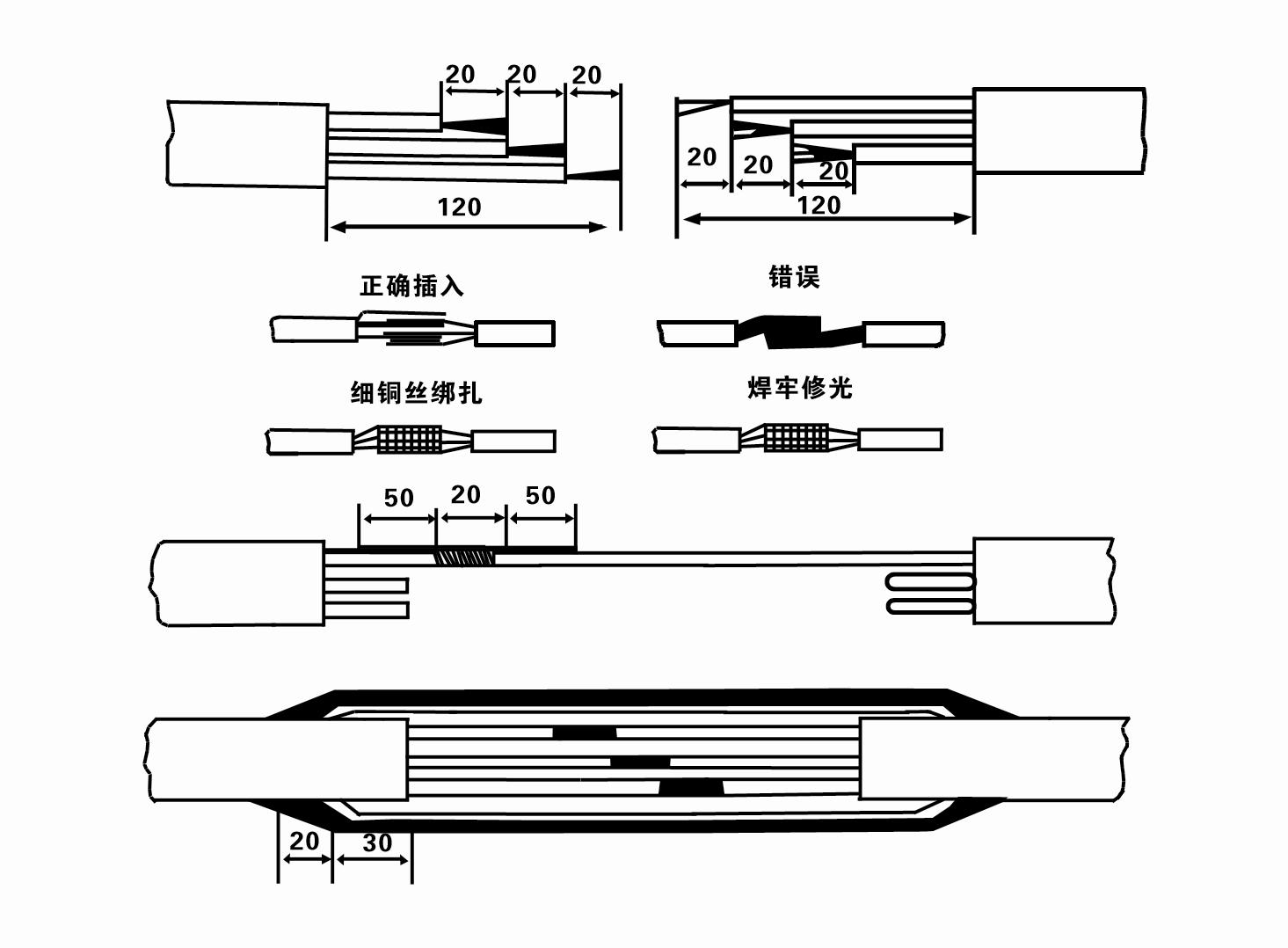
8. Uzu multimetron por kontroli ĉu la trifazaj dratoj estas konektitaj kaj ĉu la DC-rezisto estas proksimume ekvilibra.
9. Kontrolu ĉu la cirkvito kaj transformilo-kapacito estas troŝarĝitaj, kaj tiam konektu la superŝarĝan protektoŝaltilon aŭ startigan ekipaĵon. Vidu Tabelon 2 por specifaj modeloj, kaj tiam Verŝu sitelon da akvo en la akvopumpilon de la akvopumpila ellasejo por lubriki la kaŭĉukaj lagroj en la pumpilo, kaj poste metu la subakvigan elektran pumpilon vertikale kaj stabile.Komencu (ne pli ol unu sekundo) kaj kontrolu ĉu la direkta direkto kongruas kun la stira signo. Se ne, interŝanĝu iujn ajn du konektilojn de la trifaza kablo. Tiam instalu la filtrilon kaj pretiĝu por malsupreniri la puton. Se uzata en specialaj okazoj (kiel fosaĵoj, fosaĵoj, riveroj, lagetoj, lagetoj, ktp.), la elektra pumpilo devas esti fidinde surterigita.
(2) Instalaj ekipaĵoj kaj iloj:
1. Unu paro da levaj ĉenoj por pli ol du tunoj.
2. Tripiedo kun vertikala alteco ne malpli ol kvar metroj.
3. Du pendantaj ŝnuroj (drataj ŝnuroj), kiuj povas porti pezon de pli ol unu tuno (povas porti la pezon de kompleta aro da akvopumpiloj).
4. Instalu du parojn da krampoj (splitaĵoj).
5. Ŝlosiloj, marteloj, ŝraŭbturniloj, elektraj iloj kaj instrumentoj, ktp.
(3) Instalado de elektra pumpilo:
1. La instala diagramo de la subakvigebla elektra pumpilo estas montrita en Figuro 2. La specifaj instalaj dimensioj estas montritaj en Tabelo 3 "Listo de Instalaj Dimensioj de la Submergebla Elektra Pumpilo".
2. Submergeblaj elektraj pumpiloj kun kapo malpli ol 30 metroj povas esti levitaj rekte en la puton per hosoj kaj drataj ŝnuroj aŭ aliaj kanabaj ŝnuroj, kiuj povas porti la plenan pezon de la tuta maŝino, akvotuboj kaj akvo en la tuboj.
3. Pumpiloj kun kapo de pli ol 30 metroj uzas ŝtalajn tubojn, kaj la instala sekvenco estas jena:
①Uzu krampon por fiksi la supran finon de la akvopumpila parto (la motoro kaj akvopumpilo estas konektitaj ĉi-momente), levu ĝin per pendanta ĉeno kaj malrapide ligu ĝin en la puton ĝis Metu la krampon sur la puton kaj forigu la krampon. pendanta ĉeno.
② Uzu alian paron da krampoj por krampi pipon, levu ĝin per pendanta ĉeno 15 cm for de la flanĝo, kaj malrapide mallevu ĝin. Inter tubflanĝo kaj pumpflanĝo Metu la kaŭĉukan kuseneton en lokon kaj streĉu la tubon kaj pumpu egale per rigliloj, nuksoj kaj printempaj laviloj.
③ Levu la subakvigeblan pumpilon iomete, forigu la krampon sur la supra fino de la akvopumpilo, ligu la kablon firme al la akvotubo per plasta bendo, kaj malrapide ligu ĝin malsupren ĝis La krampo estas metita ĉe la puto.
④Uzu la saman metodon por ligi ĉiujn akvotubojn en la puton.
⑤Post kiam la elkonduka kablo estas konektita al la kontrolŝaltilo, ĝi estas konektita al la trifaza nutrado.
(4) Aferoj notindaj dum instalado:
1. Se oni trovas fenomenon de blokado dum la pumpado, turnu aŭ tiru la akvotubon por venki la blokadon. Se diversaj mezuroj ankoraŭ ne funkcias, bonvolu ne devigu la pumpilon malsupren por eviti damaĝon al la subakvigebla elektra pumpilo kaj la puto.
2. Dum instalado, kaŭĉuka kuseneto devas esti metita ĉe la flanĝo de ĉiu tubo kaj streĉita egale.
3. Kiam la akvopumpilo estas malaltigita en la puton, ĝi devas esti metita en la mezon de la putotubo por malhelpi la pumpilon kuri kontraŭ la putmuro dum longa tempo, kaŭzante la pumpilon vibri kaj la motoro balai kaj bruli. .
4. Determini la profundon de la akvopumpilo al la fundo de la puto laŭ la fluantaj sablo kaj siltaj kondiĉoj de la puto. Ne enterigu la pumpilon en la koto. La distanco de la akvopumpilo ĝis la fundo de la puto estas ĝenerale ne malpli ol 3 metroj (vidu Figuro 2).
5. La akvo-enira profundo de la akvopumpilo devas esti ne malpli ol 1-1,5 metroj de la dinamika akvonivelo ĝis la akva enirnodo (vidu Figuro 2). Alie, la akvopumpilaj lagroj povas esti facile difektitaj.
6. La lifto de la akvopumpilo ne povas esti tro malalta. Alie, pordega valvo devas esti instalita sur la putokapa akvodukto por kontroli la pumpilfluon ĉe la taksita flupunkto por malhelpi la motoron esti troŝarĝita kaj forbrulita pro grandaj flukvantoj.
7. Kiam la akvopumpilo funkcias, la akvoproduktado devas esti kontinua kaj eĉ, la fluo estu stabila (sub taksitaj laborkondiĉoj, ĝenerale ne pli ol 10% de la taksita kurento), kaj ne estu vibro aŭ bruo. Se estas ia anomalio, la maŝino devas esti haltigita por ekscii la kaŭzon kaj forigi ĝin.
8. Kiam vi instalas, atentu la agordon de la motora tera drato (vidu Figuro 2). Kiam la akvotubo estas ŝtala tubo, konduku ĝin de la putkapa krampo; kiam la akvotubo estas plasta tubo, konduku ĝin de la surgrunda marko de la elektra pumpilo.
After installation of the underwater pump, it is necessary to recheck the insulation resistance and three-phase continuity of the switch, and check whether the connection between the instrument and the starting equipment is wrong. If there is no problem, you can start the test machine. After starting, observe whether the indication reading of each instrument is correct. If the rated voltage and current specified on the nameplate are exceeded, observe whether the pump has any noise or vibration. If everything is normal, it can be put into operation. Four hours after the first operation of the pump, it should be turned off and the thermal insulation resistance of the motor should be quickly tested, and its value should not be less than 0.5 megaohm. After stopping the pump, it should be restarted after an interval of five minutes to prevent the water column in the pipeline from completely reversing, resulting in the motor burning due to excessive current. After the pump is put into normal operation, in order to prolong its service life, it is necessary to check regularly whether the supply voltage, working current and insulation resistance are normal. If the following conditions are found, the machine should be stopped immediately to eliminate the fault:
1 the current exceeds 20% under the rated working condition.
2 the dynamic water level drops to the inlet section, resulting in intermittent drainage.
3 the underwater pump vibrates violently or emits huge noise.
4 the supply voltage is lower than 340 volts.
5 a fuse is burned.
6 the water pipe is damaged.
7 the thermal insulation resistance of the motor to the ground is less than 0.5 megaohm.
When disassembling the device, it is necessary to untie the cable bundle and remove the pipeline part and the line protection plate. Remove the drain bolt and exclude all water in the motor chamber. Remove the filter element and loosen the screw on the coupling fixed to the motor shaft. Unscrew the bolt connecting the water inlet section and the motor, and separate the pump and the motor (pay attention to placing the device horizontally when separating to prevent the bending of the pump shaft). The sequence of disassembling the pump is as follows: (see Figure 1) water inlet section, impeller, water inlet shell, impeller. Check the valve body, and use a special tool to loosen the cone sleeve fixed to the impeller when removing the impeller. In the process of disassembly, avoid bending the pump shaft and damaging various components. The disassembly process of the motor is as follows: (see Figure 1) put the motor on the platform, and remove the nuts on the screw (pull rod bolt), base, shaft head lock nut, thrust plate, key and lower guide rail - bearing seat, bolt, and then remove the rotor (be careful not to damage the wiring harness), and finally remove the connecting parts and upper guide bearing seat. Unit assembly: before assembly, the rust and dirt of each component should be cleaned, and the sealant should be coated on each mating surface and fastener, and then assembled in the opposite order of disassembly (the movement of the motor shaft after assembly is about one millimeter), after the assembly is completed, the coupling should be flexibly rotated, and then the filter element should be placed for testing. Each time the underwater electric pump has been used for one year, or less than one year but has been immersed for two years, it must be disassembled and inspected in accordance with Article 5 and replace the worn parts.
1, elmetu la akvon en la kavon de la motoro (precipe vintre por eviti ke la motoro frostiĝu), kaj ligu bone la kablon.
2, store in an indoor room without corrosive substances and gases, with a temperature below 40 °C.
3, longtempa uzo devus atenti la rustpreventadon de submergeblaj pumpiloj.
- Impulsilo
- Ŝafta maniko
- Kaŭĉuka ŝafta maniko
-
Sigela ringo
01 Profunda puta akvokonsumado
02 Alta akvoprovizado
03 montara akvoprovizado
04 turo akvo
05 Agrikultura irigacio
06 ĝardeno irigacio
07 rivera akvopreno
08 hejma akvo

