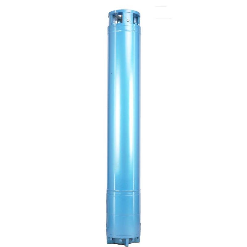
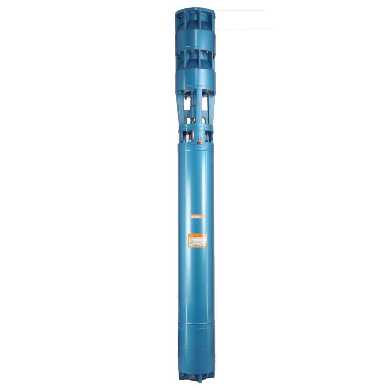
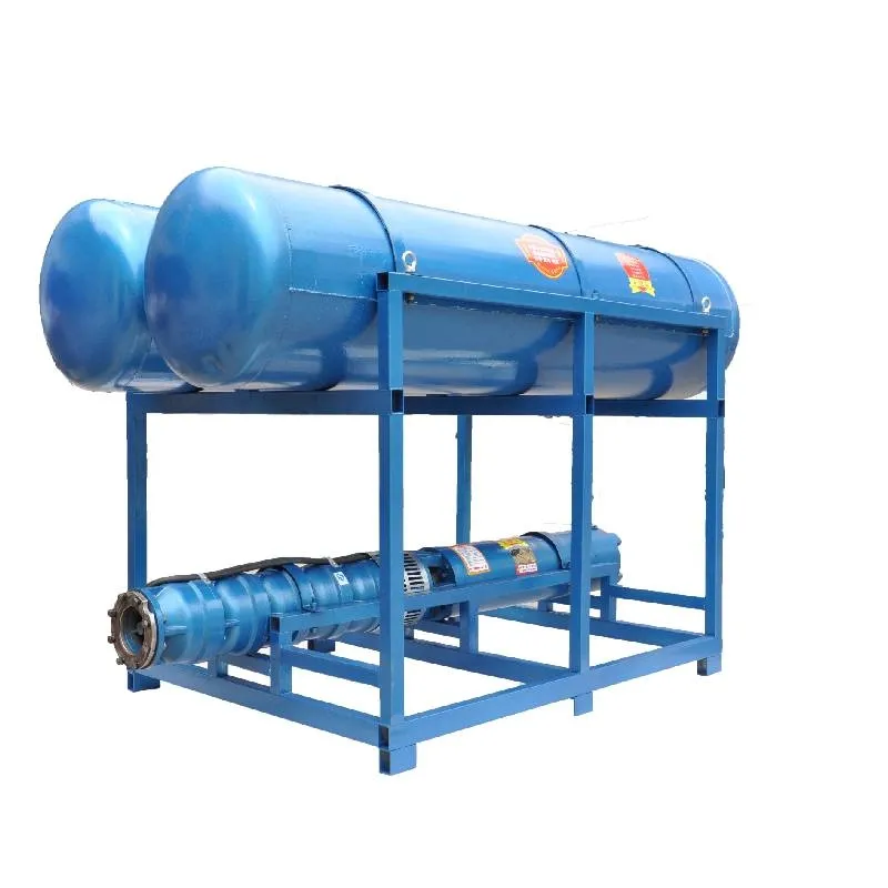
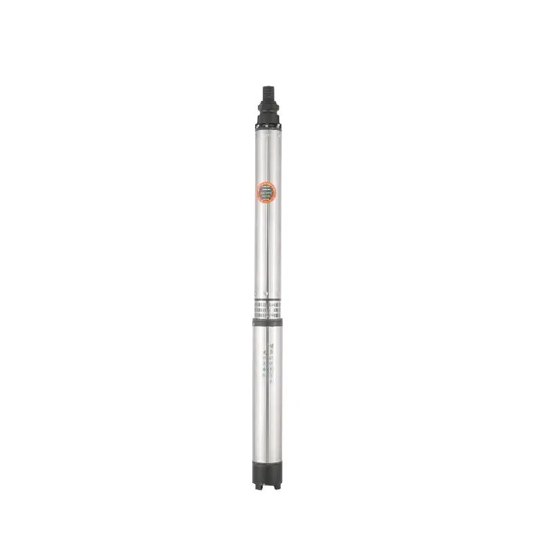
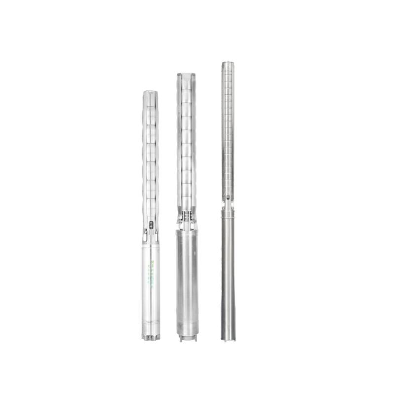
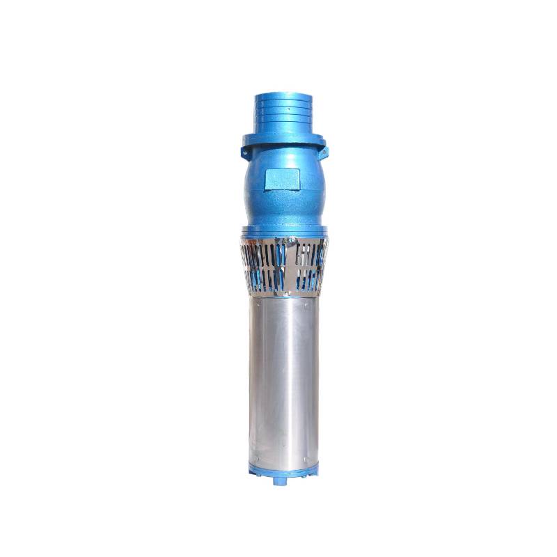
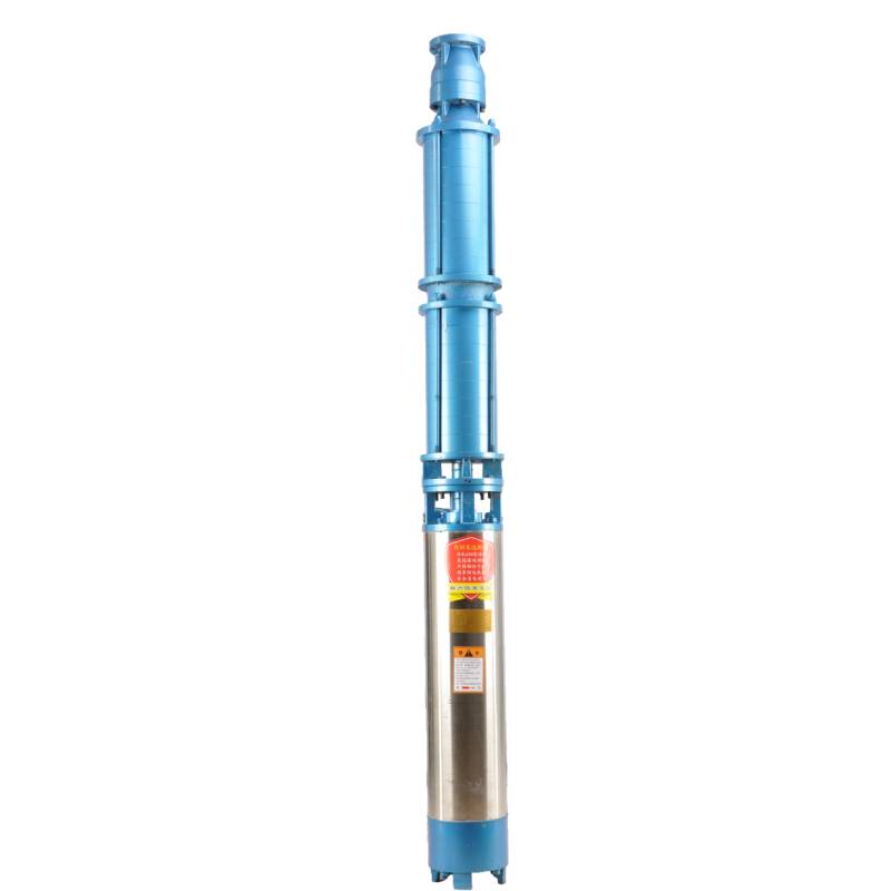
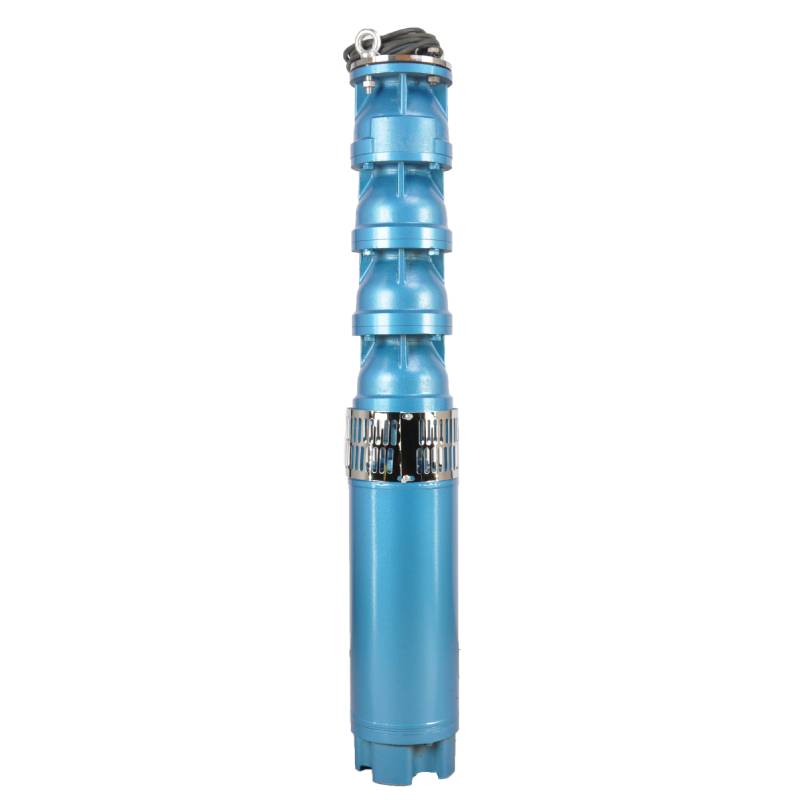
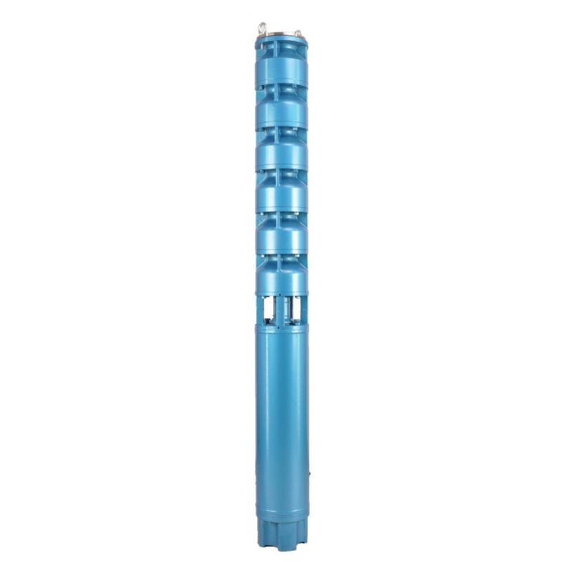
This hot water pump adopts the motor made of 50W400 grade high quality cold rolled silicon steel, which is stamped by high speed punch press. It has the advantages of low stator iron loss and low self-heating. The motor winding is designed for hot water pump, high temperature resistance and anti-aging. The winding has water resistance, and adopts 3CR13 stainless steel blade shaft, high temperature resistant bushing and other high quality accessories to enable it to operate for a long time at high temperature, and can be used with frequency converter, so as to automatically adjust according to the amount of water used. This hot water pump is the ideal choice for your hot water equipment, which can operate stably and efficiently, providing you with a lasting hot water supply.
The product is a three-phase AC 380V (tolerance + / - 5%), 50HZ (tolerance + / - 1%) power supply submersible pump. With water quality requirements: water temperature is not higher than 20 °C; solid impurities content (mass ratio) is not more than 0.01%; PH value (pH) is 6.5-8.5; hydrogen sulfide content is not more than 1.5mg/L; chloride ion content is not more than 400mg/L. The electric pump adopts closed or water sealed wet structure, before use must be submersible motor inner cavity filled with clean water to prevent empty, and then tighten the water and air bolts, otherwise not to use. Its work should be completely immersed in water, immersion depth is not more than 70 meters, the distance between the bottom of the pump and the bottom of the well is not less than 3 meters. Well water inflow quantity should be able to meet the electric pump water output and continuous operation, the output water quantity should be controlled at 0.7-1.2 times of the rated flow. The well should be vertical, the electric pump can not be used horizontally or inclined, only vertically placed. The electric pump must be equipped with cables and external overload protection device as required. It is strictly prohibited to conduct no-load test under no water condition.
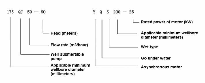
| Model | Flow (m3/h) | Caput (m) |
Rotatingspeed (Mutatio / punctum) |
Aqua sentinam(%) | Outlet diametri (mm) |
Lorem bene diametri (mm) |
Ratum power(KW) |
Ratum voltage(V) |
Ratum current (A * |
Motorefficiency (%) | power factorcosφ | Unitas Aculeis Maximus amplitudo (mm) |
Animadverte | |||||||||
| 300QJ200-40 | 200 | 40 | 2900 | 76 | 150 | 300supra | 37 | 380 | 77.8 | 85.0 | 0.85 | 281 | ||||||||||
| 300QJ200-60 | 60 | 55 | 115 | 85.5 | 0.85 | |||||||||||||||||
| 300QJ200-80 | 80 | 75 | 154.1 | 86.0 | 0.86 | |||||||||||||||||
| 300QJ200-100 | 100 | 90 | 183.8 | 86.5 | 0.86 | |||||||||||||||||
| 300QJ200-120 | 120 | 100 | 204.3 | 86.5 | 0.86 | |||||||||||||||||
| 300QJ200-140 | 140 | 125 | 249.5 | 87.5 | 0.87 | |||||||||||||||||
| 300QJ200-160 | 160 | 140 | 277.8 | 88.0 | 0.87 | |||||||||||||||||
| 300QJ200-180 | 180 | 160 | 317.5 | 88.0 | 0.87 | |||||||||||||||||
| 300QJ200-200 | 200 | 185 | 367.2 | 88.0 | 0.87 | |||||||||||||||||
| 300QJ200-240 | 240 | 220 | 436.6 | 88.0 | 0.87 | |||||||||||||||||
| 300QJ320-30 | 320 | 30 | 2900 | 77 | 200 | 300supra | 45 | 380 | 94.6 | 85.0 | 0.85 | 281 | ||||||||||
| 300QJ320-60 | 60 | 90 | 183.8 | 86.5 | 0.86 | |||||||||||||||||
| 300QJ320-90 | 90 | 125 | 249.5 | 87.5 | 0.87 | |||||||||||||||||
| 300QJ320-120 | 120 | 160 | 317.5 | 88.0 | 0.87 | |||||||||||||||||
1, well submersible pump for clean water pump, prohibit the new well, pumping sediment and muddy water,
2, well water pump voltage grade of 380/50HZ, the use of other voltage grades of submersible motors need to be customized. The underground cable must use waterproof cable, must be equipped with starting equipment, such as distribution box, start not ready should have commonly used motor comprehensive protection function, such as short circuit overload protection, phase protection, undervoltage protection, grounding protection, idling protection, in case of abnormal conditions, the protection device should be timely action trip.
3, the installation and use of the pump must be reliably grounded, prohibit the push and pull switch when the hands and feet are wet, the installation and maintenance of the pump must be cut off the power supply, the use of the pump place to set up "to prevent electric shock" obvious signs:
4, down the well or before installation, the motor cavity must be filled with distilled water or non-corrosive clean cold boiling water, tighten the / water bolt, the pump on the ground test run, must be to the pump chamber water lubrication rubber bearings, instant start not more than a second, see whether the steering is the same as the steering instructions. When the pump is upright, pay attention to safety, prevent overturning injury.
V, stricte secundum praescripta sentinae tollunt, fluunt usui, ne humilis fluat vel alta vi flare tollat, impulsus sustinens et alias partes indumenti, motor oneris combustus.
VI, post sentinam putei, mensura motoris ad terram resistentia velit non minus quam 100M esse, post initium intentionis et currentis observare, sisto motore sinuoso velit, sive secundum requisita; sentinam repono locationis temperaturae si minus quam punctum congelatur, aqua in cavitate motoria sicca debet, ne aquae motoris cavitas glaciei damnum per frigiditas temperatura exstinguat.
The pump part is mainly composed of pump shaft, impeller, shunt shell, rubber bearing, check valve body (optional) and other components. The motor part is mainly composed of base, pressure regulating diaphragm, thrust bearing, thrust plate, lower guide bearing seat, stator, rotor, upper guide bearing seat, sand discharging ring, water inlet section, lead cable and other components. The main characteristic of this product is that the motor is a water-cooled submersible three-phase asynchronous motor, and the motor cavity is filled with water to cool the motor and lubricate the bearing. The pressure regulating diaphragm at the bottom is used to adjust the expansion-contraction pressure difference in the body caused by the change of the temperature rise of the motor. In order to prevent the sand particles in the well water from entering the motor, two oil seals are installed at the upper end of the motor shaft extension, and a sand discharging ring is installed to form a sand discharging structure. In order to prevent the pump shaft from jumping when starting, the pump shaft and the motor shaft are connected together through a coupling, and a thrust bearing is installed at the bottom of the motor. The lubrication of the motor and the pump bearing is realized through water lubrication. The stator winding of the motor is made of high-quality well motor winding wire, with high insulation performance. The pump is designed by computer CAD, with simple structure and good technical performance.

(I) Praeparatio ante institutionem:
1. Perspice an sentinam submersibilem usui conditionibus occurrat et ambitum in manuali definitum.
2. Utens obiectu gravi cum diametro aequali maximo diametro exterioris sentinae submersibilis, metire an inneldiametri putoris sentinam submersibilem aptare possit, et metire an puteus profundus ad institutionem requisita occurrat.
3. Reprehendo utrum puteus mundus sit, et si puteus aqua turbidus est. Numquam uti sentinam electricam submersibilem ad lavandum putorem sentinam lutum et aquam arenam ad vitandum praematurum damnum ad sentinam electricam submersibilem.
4. Reprehendo an positio fibulae institutionis welhead sit conveniens et an qualitatem totius unitatis sustinere possit
5. Reprehendo si partes sentinae submersibiles sint perfectae et rite institutae secundum schematis conventus in manu-Removeo velum colum et gyrari queat ad videndum an mollius circumagatur.
6. Aquam cochleae et cavum mobilem reple, non mordax aqua (ex corrosivis (vide ut eam sursum), tum obstringas aqualram. Post 12 horas aquae injectiones, insulatio motoris resistentia non minus quam 150M Q mensurata est cum 500V tabula quatiens.
7. Cable joint, cut off a 120mm rubber sleeve from one end of the outgoing cable and the matching cable with an electrician's knifethen stagger the length of the three core wires in a stepped shape, peel off a 20mm copper core, scrape of the oxide layer on theoutside of the copper wire with a knife or sand cloth, and insert the two connected wire ends in palirs.After tying the layer tightly with fine copper wire, solder it thoroughly and firmly, and sand of any. burrs on the surface. Then, forthe three joints, use polyvester insulation tape to wrap them in a semi stacked manner for three lavers. Wrap the two ends of thewrapping layer tightywith nyion thread,and then use a semi stacked method to wrap the tape for three layers. Wrap the outellayer with high-pressure insulation tape for three layers. Finally, fold the threestrands together and repeatedly wrap them for fivelayers with high-pressure tape. Each layer must be tightly tied, and the interlayer joints must be tight and fimm to prevent water frompenetrating and damaging the insulation, After wrapping, soak in water at room temperature of 20 ’c for 12 hours, and measurethe insulation resistance with a shaking table, which should not be less than 100M Ω
Adnexa funis processus schematis wiring talis est: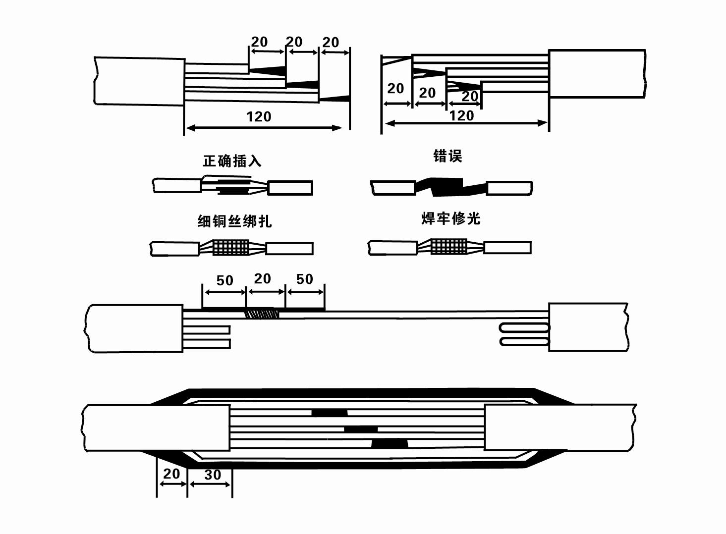
8. Multimetro utere ad reprimendam num tria-phasma fila connexa sint et an resistentia DC proxime libratum sit.
9. Perscriptio num ambitus et transformantis capacitas cumulatur, et tunc coniunge cum onere transitum tutelae vel apparatum incipiens. Vide Tabulam 2 ad exempla specifica, et mitte situlam aquae in sentinam aquae ex aqua sentinae exitum ad praestringendum iuvantis gestus in sentinam, et pone sentinam submersibilem electricam erectam et constantem.Start (non plus quam unum secundum) et vide utrum directio gubernii sit cum signo gubernaculo consonans. Sin minus, aliquos duos connexiones trium-phase cables permuto. Deinde colum inaugurare et ad puteum descendere parant. Si in peculiaribus occasionibus adhibeantur (sicut fossae, fossae, flumina, stagna, stagna, etc.), sentinam electricam certo fundari debent.
(2) Installation instrumentorum et instrumentorum;
1. Unum par catenarum levandi plus duobus talentis.
2. Tripode cum perpendiculo non minus quam quattuor metra.
3. Duo funes suspensi (funes filum) qui pondus plus quam unum ton ferre possunt (pondere aquae soleatus completae).
4. duo paria fibulatorum inaugurare (facile).
5. Clavis, malleis, verticillis, instrumentis electricis et instrumentis, etc.
(III) Electric sentinam institutionem:
1. Tabulae institutionis sentinae submersibilis electrici in Figura ostenditur 2. Specificae institutiones dimensiones in Tabula 3 monstrantur "Index institutionis Dimensiones Submersible Electric Pump".
2. Solatus electrici submersibiles cum capite minore quam 30 metra directe levari possunt in puteum caligarum et funiculos filum vel alias funiculos cannabinos, qui plenum pondus totius machinae, fistulae aquae et aquae in tibiis ferre possunt.
3. Pumps cum capite plusquam 30 metrorum utimur fistulis ferreis, et series institutionis haec est:
① Fibulae utere ad fibulae partem superiorem sentinam aquae (motricis et aquae sentinae hoc tempore coniunctae sunt), eam cum cathena pensili tolle, et lente eam in puteum ligabis, donec Fibulae in putei caput auferas et removeas. catena pendula.
② Alterum par fibularum utere ad fistulam fibulae, eam leva cum cathena pendula 15 cm a LABIUM, et lente deprime. Inter fistulam LABIUM et sentinam flangePut Flexilis caudex in loco, et obstringere tibiam et sentinam aequabiliter cum valvis, nucibus et lavatoribus veris.
③ Sentinam submersibilem leviter tolle, fibulam in superiore fine aquae sentinae tolle, funem ligabis ad fistulam aquae cum taenia plastica firmiter, et lente ligabis eam donec Fibulae ad putei caput ponatur.
Eadem methodo omnes aquae fistulas in puteum alligant.
⑤Post funem plumbeum ad imperium transitum coniungitur, cum copia trium phase iungitur.
(4.) Notae in installation:
1. Si vallum phaenomenon in flantibus processum inveniatur, vertere vel fistulam aquam trahere, ut punctum vallum superetur. Si variae mensurae adhuc non operantur, quaeso Noli sentinam cogere ad vitandum damnum in sentinam electricam et puteum submersibilem.
2. In institutione, codex iuvantis ad cuiusque fistulae LABIUM collocari debet et aequaliter coarctari.
3. Cum aqua sentina in puteum demissa, in media fistula putei poni debet, ne sentinam contra murum putei diu curreret, sentinam pulsum et motorem verrere et comburere. .
4. Determinare profunditatem aquae sentinae ad imum putei iuxta arenam fluentem et condiciones putei limum. Sentinam in luto non sepelias. Distantia aquae sentinae ad fundum putei fere non minus quam 3 metra (vide figura 2).
5. Aquae viscus profunditas aquae sentinae non minus esse debet quam 1-1.5 metra a gradu aquae dynamicae ad nodi aquae diverticulum (vide Figure 2). Alioquin aquae sentinae gestus facile laedantur.
6. Aquae levare sentinam nimis humilis esse non potest. Alioquin valvae portae aquae putei fistulae inaugurari debet ut fluere sentinam fluere apud punctum aestimatum fluere prohibeat ne motor oneretur et exuratur propter magnas rates fluxus.
7. Cum aqua currit sentina, aqua output continuum et par esse debet, currens sit stabilis (sub condiciones operationis aestimatae, plerumque non plus quam 10% currentis aestimatae), nec vibratio nec strepitus esse debet. Si qua deprauatio est, machina cessari debet causam cognoscendi et removendi.
8. Cum inaugurari, attende ad occasum filum fundationis motoris (vide Figure 2). Fistula cum aqua est ferrea tibia, a puteo fibulato duc; cum fistula aquatica fistula plastica est, eam a fundamento sentinae electrici notam duc.
After installation of the underwater pump, it is necessary to recheck the insulation resistance and three-phase continuity of the switch, and check whether the connection between the instrument and the starting equipment is wrong. If there is no problem, you can start the test machine. After starting, observe whether the indication reading of each instrument is correct. If the rated voltage and current specified on the nameplate are exceeded, observe whether the pump has any noise or vibration. If everything is normal, it can be put into operation. Four hours after the first operation of the pump, it should be turned off and the thermal insulation resistance of the motor should be quickly tested, and its value should not be less than 0.5 megaohm. After stopping the pump, it should be restarted after an interval of five minutes to prevent the water column in the pipeline from completely reversing, resulting in the motor burning due to excessive current. After the pump is put into normal operation, in order to prolong its service life, it is necessary to check regularly whether the supply voltage, working current and insulation resistance are normal. If the following conditions are found, the machine should be stopped immediately to eliminate the fault:
1 the current exceeds 20% under the rated working condition.
2 the dynamic water level drops to the inlet section, resulting in intermittent drainage.
3 the underwater pump vibrates violently or emits huge noise.
4 the supply voltage is lower than 340 volts.
5 a fuse is burned.
6 the water pipe is damaged.
7 the thermal insulation resistance of the motor to the ground is less than 0.5 megaohm.
When disassembling the device, it is necessary to untie the cable bundle and remove the pipeline part and the line protection plate. Remove the drain bolt and exclude all water in the motor chamber. Remove the filter element and loosen the screw on the coupling fixed to the motor shaft. Unscrew the bolt connecting the water inlet section and the motor, and separate the pump and the motor (pay attention to placing the device horizontally when separating to prevent the bending of the pump shaft). The sequence of disassembling the pump is as follows: (see Figure 1) water inlet section, impeller, water inlet shell, impeller. Check the valve body, and use a special tool to loosen the cone sleeve fixed to the impeller when removing the impeller. In the process of disassembly, avoid bending the pump shaft and damaging various components. The disassembly process of the motor is as follows: (see Figure 1) put the motor on the platform, and remove the nuts on the screw (pull rod bolt), base, shaft head lock nut, thrust plate, key and lower guide rail - bearing seat, bolt, and then remove the rotor (be careful not to damage the wiring harness), and finally remove the connecting parts and upper guide bearing seat. Unit assembly: before assembly, the rust and dirt of each component should be cleaned, and the sealant should be coated on each mating surface and fastener, and then assembled in the opposite order of disassembly (the movement of the motor shaft after assembly is about one millimeter), after the assembly is completed, the coupling should be flexibly rotated, and then the filter element should be placed for testing. Each time the underwater electric pump has been used for one year, or less than one year but has been immersed for two years, it must be disassembled and inspected in accordance with Article 5 and replace the worn parts.
I, aquam in cavo motorio extingue (praesertim hieme ne motor a frigore) et funem bene ligaveris.
2, store in an indoor room without corrosive substances and gases, with a temperature below 40 °C.
III, diu terminus usus observandum ne rubigo soleatus submersible.
- Impeller
- hastile sleeve
- Flexilis scapus sleeve
-
signantes anulum
I Aquam profunda bene attractio
II High-surgere aquarum copia
03 mons aquae copia
04 aqua turris
05 Irrigatio agriculturae
VI hortus irrigationis
07 attractio aquae fluminis
08 aqua domestica

