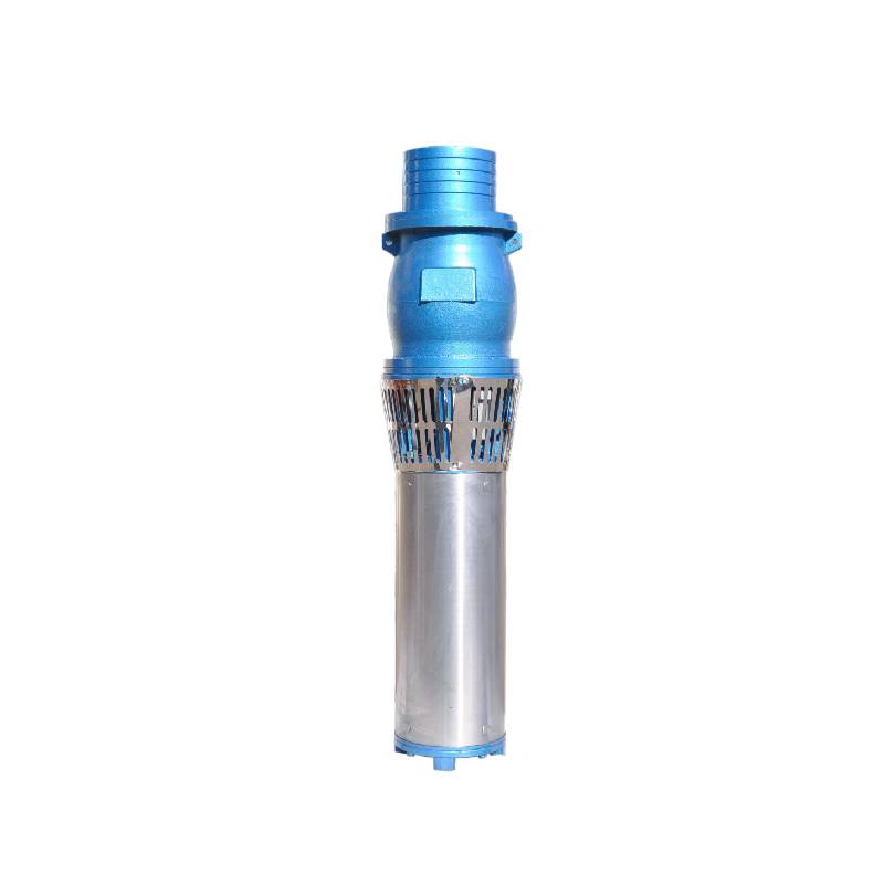
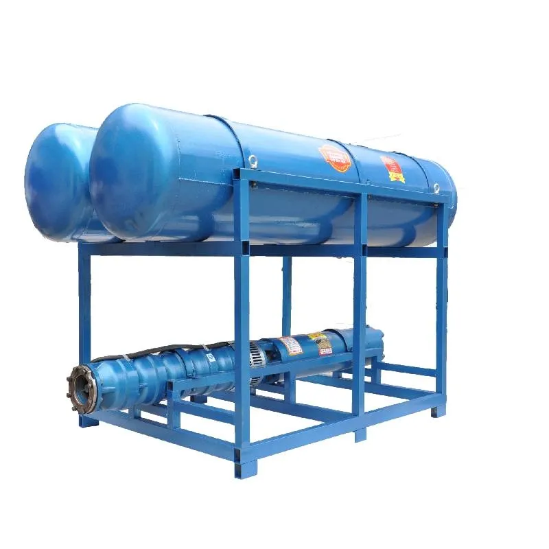
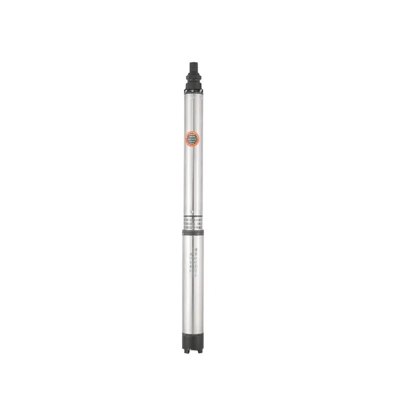
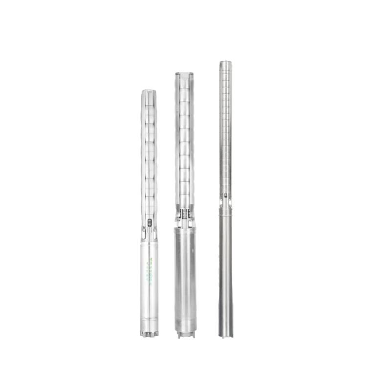
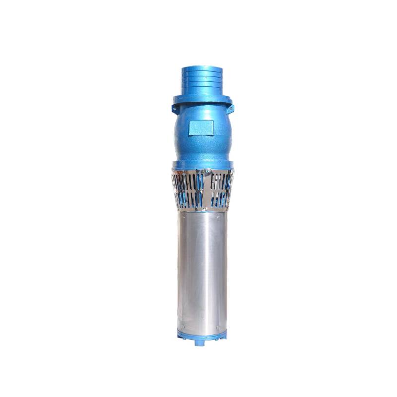
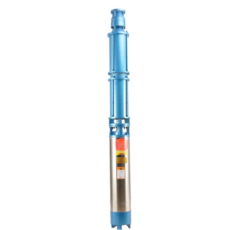
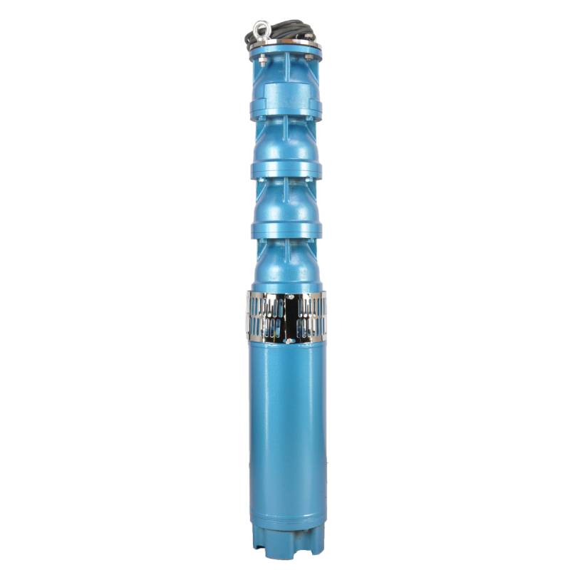
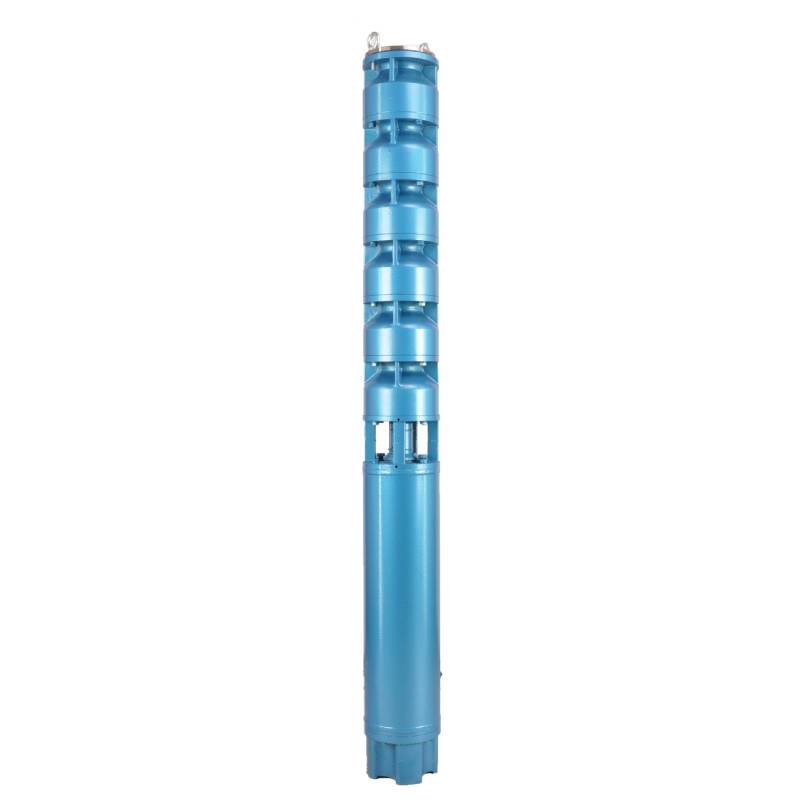
Well-designed sand-proof large flow water system, using water-immersed motor, no oil after burning machine does not pollute water. Suitable for freshwater aquaculture extraction of river water, sea water oxygen. Flow range 100-1000m3/h, lift 3-100m, power 3-100KW.
1、電源:三相AC 380V(許容誤差+/- 5%)、50HZ(許容誤差+/- 1%)。
2、水質:
(1) water temperature is not higher than 20 °C;
(2)固形不純物含有量(質量比)が0.01%以下であること
(3)PH値(pH)6.5~8.5
(4)硫化水素含有量が1.5mg/L以下であること
(5)塩化物イオン含有量が400mg/L以下であること。
3、モーターは密閉型または水入りの湿式構造であるため、使用前に水中モーターキャビティをきれいな水で満たして、誤って満水にならないようにし、その後、水注入、エア抜きボルトを締めてください。そうしないと、使用できません。
4、水中ポンプは水中に完全に沈んでいなければならず、潜水深度は70m以下で、井戸底からの水中ポンプの底部は3m以上である必要があります。
5、井戸水の流量は水中ポンプの給水量と連続運転量を満たす必要があり、水中ポンプの給水量は定格流量の0.7~1.2倍に制御する必要があります。
6、井戸は真っ直ぐでなければならず、水中ポンプは使用したり捨てたりすることができず、垂直にのみ使用できます。
7、水中ポンプは、要求に応じてケーブルと外部過負荷保護装置を一致させる必要があります。8、ポンプは水無負荷試験機なしでは厳禁です。
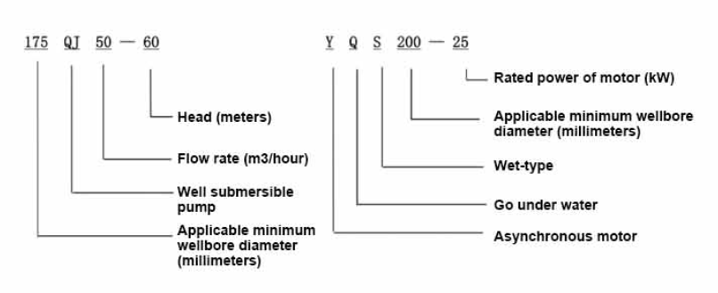
| 200 QS 水中ポンプ性能表 非標準カスタマイズシリーズ |
||||||||
| モデル | モデル | |||||||
| QS5-70-2.2KW | QS10-52-4KW | |||||||
| QS5-90-3KW | QS10-70-5.5KW | |||||||
| QS5-108-4KW | QS10-90-7.5KW | |||||||
| QS5-126-5.5KW | QS10-108-7.5KW | |||||||
| QS5-144-5.5KW | QS20-40-4KW | |||||||
| QS5-160-7.5KW | QS20-54-5.5KW | |||||||
| QS5-180-7.5KW | QS20-65-7.5KW | |||||||
| QS10-36-2.2KW | QS20-81-7.5KW | |||||||
| QS10-54-3KW | QS32-13-2.2KW | |||||||
| QS10-70-4KW | QS32-26-4KW | |||||||
| QS10-90-5.5KW | QS32-52-7.5KW | |||||||
| QS10-108-5.5KW | QS40-39-7.5KW | |||||||
| QS10-126-7.5KW | QS40-13-4KW | |||||||
| QS10-140-7.5KW | QS40-26-5.5KW | |||||||
| QS15-38-3KW | QS50-13-4KW | |||||||
| QS15-54-4KW | QS50-26-5.5KW | |||||||
| QS15-65-5.5KW | QS50-39-7.5KW | |||||||
| QS15-81-5.5KW | QS63-12-4KW | |||||||
| QS15-100-7.5KW | QS63-24-7.5KW | |||||||
| QS20-30-3KW | QS80-11-4KW | |||||||
| QS20-45-4KW | QS80-22-7.5KW | |||||||
| QS20-60-5.5KW | QS10-88-7.5KW | |||||||
| QS20-75-7.5KW | QS10-105-7.5KW | |||||||
| QS20-81-7.5KW | QS40-52-11KW | |||||||
| QS10-198-15KW | QS50-60-11KW | |||||||
| QS10-160-9.2KW | QS65-30-9.2KW | |||||||
| QS15-180-15KW | QS80-28-9.2KW | |||||||
| QS10-180-11KW | QS125-15-7.5KW | |||||||
This well submersible pump is a clean water pump. It is strictly prohibited to excavate new wells, discharge sediments and muddy water. The voltage rating of the pump is 380/50 hertz, and other voltage ratings are not allowed. The submersible motor needs to be customized, and the underground cable must be waterproof cable, and must be equipped with starting equipment, such as distribution box, etc. The starting equipment should have common motor comprehensive protection functions, such as short circuit overload protection, phase loss protection, undervoltage protection, grounding protection and idling protection, etc. In order to prevent abnormal conditions, the protection device should be timely trip. During the installation and use process, the pump must be reliably grounded. It is strictly prohibited to push and pull the switch when hands and feet are wet. The power supply must be cut off before installation and maintenance of the pump. An obvious "anti-electric shock" sign must be set up where the pump is used. Before going down the well or installing, the motor must fill the inner cavity with distilled water or non-corrosive clean cold water, and the inlet and outlet bolts must be tightened. When testing the pump, the pump cavity must be filled with water to lubricate the rubber bearings, and the instant start time shall not exceed one second to check whether the direction is correct. Pay attention to safety when lifting, and prevent the overturning of the pump from causing injury. Strictly according to the provisions of the pump lift and flow range, to prevent the pump in low lift when the large flow or in high lift when the large pull, resulting in serious wear and tear of thrust bearings and other parts, causing motor overload and burnout. After the pump into the well, the insulation resistance between the motor and the ground should not be less than 100MΩ, after the start of regular observation of voltage and current, and check whether the motor winding insulation meets the requirements; if the pump storage temperature below freezing, the water in the motor cavity should be discharged to prevent the cold temperature caused by the motor cavity water icing and damage the motor due to low temperature.
構造の簡単な紹介:ポンプ部分は主にポンプシャフト、インペラ、転流シェル、ゴムベアリング、チェックバルブ本体(オプション部品)などの部品で構成されています。モーター部分は主にベース、圧力調整フィルム、スラストベアリング、スラストプレート、下部ガイドベアリングシート、ステーター、ローター、上部ガイドベアリングシート、サンドリング、水入口セクション、ケーブルなどの部品で構成されています。
製品の主な特徴は次のとおりです。
1、モーターは水を満たした湿式水中三相非同期モーターで、モーターキャビティはきれいな水で満たされ、モーターの冷却とベアリングの潤滑に使用され、モーターの底部の圧力調整フィルムは、モーターの温度上昇の変化によって引き起こされる本体内の水の膨張と収縮の圧力差を調整するために使用されます。
2、井戸水中の砂がモーター内に侵入するのを防ぐため、モーター軸の上端にオイルシールを2個装備し、さらにサンドリングを設置して砂侵入防止構造を形成しています。
3、始動時にポンプ軸が跳ね上がるのを防止するため、ポンプ軸とモーター軸をカップリングで接続し、モーター下部に上部スラストベアリングを設置しています。
4、モーターとポンプベアリングの潤滑は水潤滑です。
5、モーターのステーター巻線は、高い絶縁性能を備えた高品質の水中モーター巻線で作られています。
6、ポンプはコンピュータCADによって設計されており、構造がシンプルで技術的な性能が優れています。

(1)設置前の準備:
1. 水中ポンプがマニュアルに指定された使用条件と範囲を満たしているかどうかを確認します。
2. 水中ポンプの最大外径に等しい直径の重い物体を使用して、井戸の内径が水中ポンプに適合するかどうかを測定し、井戸の深さが設置要件を満たしているかどうかを測定します。
3. 井戸が清潔かどうか、井戸水が濁っていないかどうかを確認します。水中電動ポンプの早期損傷を避けるため、水中電動ポンプを使用して井戸ポンプの泥や砂水を洗浄しないでください。
4. ウェルヘッド取り付けクランプの位置が適切かどうか、ユニット全体の品質に耐えられるかどうかを確認します。
5. 水中ポンプの部品が揃っていて、マニュアルの組み立て図に従って正しく取り付けられているかどうかを確認します。フィルタースクリーンを取り外し、カップリングを回転させて、柔軟に回転するかどうかを確認します。
6. 水栓を緩めて、モーターの空洞に清潔で腐食しない水を入れ(注:必ず満たしてください)、水栓を締めます。12 時間の注水後、500V 振動台で測定した場合、モーターの絶縁抵抗は 150M Q 以上である必要があります。
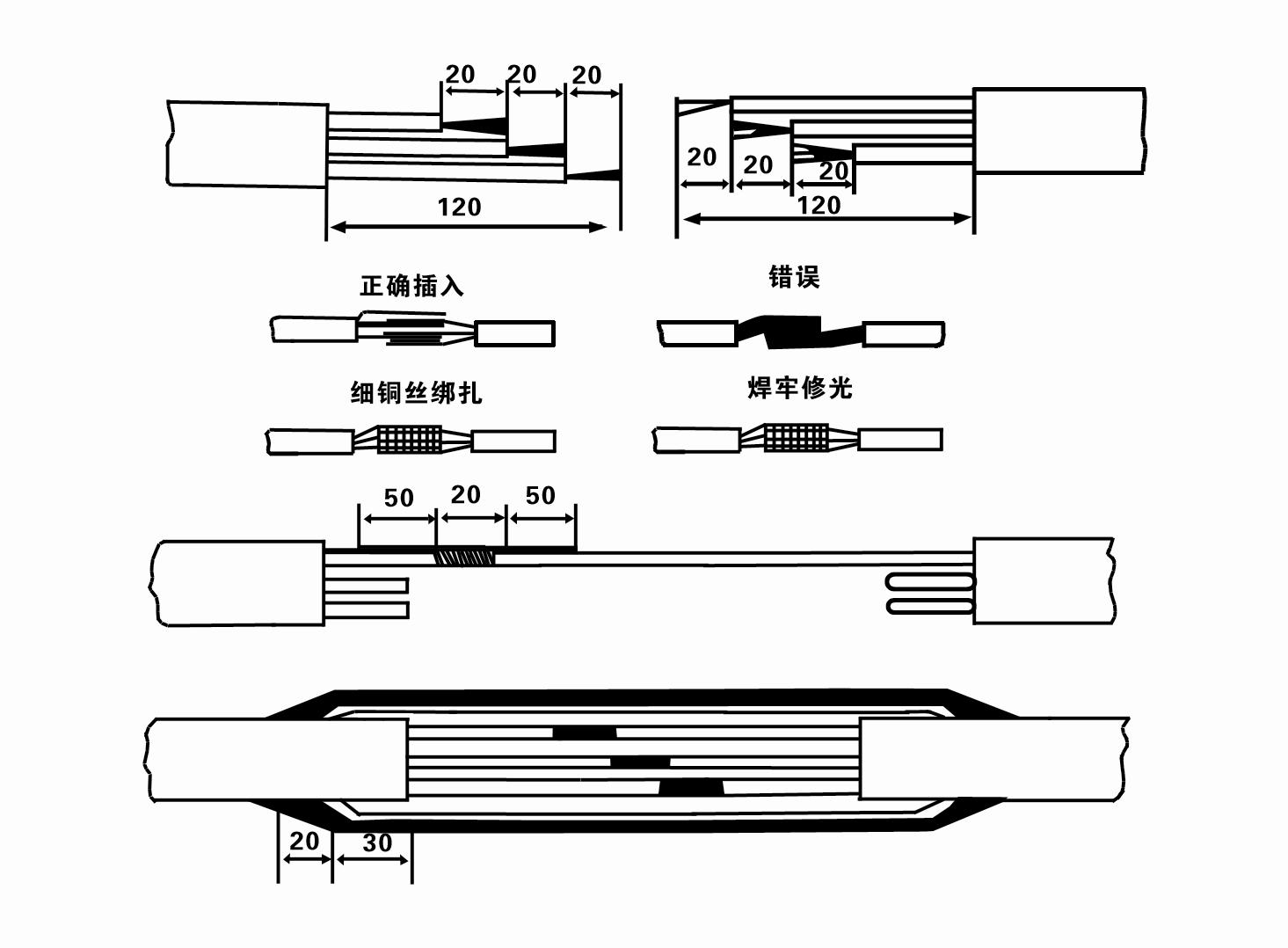
7. Cable joint, cut off a 120mm rubber sleeve from one end of the outgoing cable and the matching cable with an electrician's knifethen stagger the length of the three core wires in a stepped shape, peel off a 20mm copper core, scrape of the oxide layer on theoutside of the copper wire with a knife or sand cloth, and insert the two connected wire ends in palirs.After tying the layer tightly with fine copper wire, solder it thoroughly and firmly, and sand of any. burrs on the surface. Then, forthe three joints, use polyvester insulation tape to wrap them in a semi stacked manner for three lavers. Wrap the two ends of thewrapping layer tightywith nyion thread,and then use a semi stacked method to wrap the tape for three layers. Wrap the outellayer with high-pressure insulation tape for three layers. Finally, fold the threestrands together and repeatedly wrap them for fivelayers with high-pressure tape. Each layer must be tightly tied, and the interlayer joints must be tight and fimm to prevent water frompenetrating and damaging the insulation, After wrapping, soak in water at room temperature of 20 ’c for 12 hours, and measurethe insulation resistance with a shaking table, which should not be less than 100M Ω
添付のケーブル配線工程図は以下のとおりです。
8. マルチメーターを使用して、三相配線が接続されているかどうか、および DC 抵抗がほぼバランスしているかどうかを確認します。
9.回路と変圧器の容量が過負荷になっていないか確認し、過負荷保護スイッチまたは始動装置を接続します。具体的なモデルについては表2を参照してください。次に、バケツの水を水ポンプ出口から水ポンプに注ぎ、ポンプ内のゴムベアリングを潤滑してから、水中電動ポンプを垂直に安定させます。始動(1秒以内)し、ステアリング方向がステアリングサインと一致しているかどうかを確認します。一致しない場合は、3相ケーブルの任意の2つのコネクタを交換します。次に、フィルターを取り付けて、井戸を下る準備をします。特別な場合(溝、溝、川、池、池など)で使用する場合は、電動ポンプを確実に接地する必要があります。
(2)設置設備及び工具:
1. 2トン以上の場合は吊り上げチェーン1組。
2. 垂直の高さが4メートル以上の三脚。
3. 1トン以上の重量に耐えられる吊りロープ(ワイヤーロープ)2本(水ポンプ一式の重量に耐えられる)。
4. クランプ(添え木)を2組取り付けます。
5. レンチ、ハンマー、ドライバー、電動工具、器具等
(3)電動ポンプの設置:
1. 水中電動ポンプの設置図を図2に示します。具体的な設置寸法は表3「水中電動ポンプの設置寸法一覧」に示します。
2. 揚程が 30 メートル未満の水中電動ポンプは、機械全体、水道管、およびパイプ内の水の全重量に耐えられるホースとワイヤーロープまたはその他の麻ロープを使用して、井戸に直接吊り上げることができます。
3. 揚程が30メートルを超えるポンプには鋼管が使用され、設置手順は次のとおりです。
①水ポンプ部分(この時点ではモーターと水ポンプは接続されています)の上端をクランプで挟み、吊りチェーンで持ち上げ、ゆっくりと井戸の中に結び付けます。クランプを井戸頭に当て、吊りチェーンを外します。
②別のクランプでパイプを挟み、吊りチェーンでフランジから15cm離れたところまで持ち上げ、ゆっくり下ろします。パイプフランジとポンプフランジの間にゴムパッドを置き、ボルト、ナット、スプリングワッシャーでパイプとポンプを均等に締めます。
③水中ポンプを少し持ち上げ、水中ポンプの上端にあるクランプを外し、ケーブルをビニールテープで水道管にしっかりと結び、クランプが井戸元に当たるまでゆっくりと締め付けます。
④同じ方法で、すべての水道管を井戸に結びます。
⑤引き出しケーブルを制御スイッチに接続した後、三相電源に接続します。
(4)設置時の注意事項
1. ポンプの作業中に詰まり現象が見つかった場合は、水道管を回すか引っ張って詰まり箇所を解消してください。それでもさまざまな対策が効かない場合は、水中電動ポンプと井戸の損傷を防ぐため、ポンプを無理に押し下げないでください。
2. 取り付け時には、各パイプのフランジにゴムパッドを置き、均等に締め付けます。
3. 水ポンプを井戸に降ろすときは、ポンプが井戸壁に長時間ぶつかって振動したり、モーターが回転して焼損したりしないように、井戸パイプの中央に配置する必要があります。
4. 井戸の砂やシルトの流動状況に応じて、井戸底までの水ポンプの深さを決定します。ポンプを泥の中に埋めないでください。水ポンプから井戸底までの距離は、通常 3 メートル以上です (図 2 を参照)。
5. 水ポンプの浸水深は、動水位から水入口ノードまで 1 ~ 1.5 メートル以上である必要があります (図 2 を参照)。そうでない場合、水ポンプのベアリングが簡単に損傷する可能性があります。
6. 水ポンプの揚程は低すぎてはいけません。低すぎる場合は、定格流量点でポンプの流量を制御するゲートバルブを井戸元水パイプラインに設置して、大流量によるモーターの過負荷や焼損を防ぐ必要があります。
7. 水ポンプが作動しているとき、水の出力は連続的かつ均一で、電流は安定している必要があります(定格動作条件下では、通常、定格電流の10%以下)、振動や騒音はありません。異常がある場合は、機械を停止して原因を突き止め、除去する必要があります。
8. 設置時には、モーターのアース線の設定に注意してください(図2を参照)。水道管が鋼管の場合は、井戸頭クランプから引き出します。水道管がプラスチック管の場合は、電動ポンプのアースマークから引き出します。
- 1.After the submersible electric pump is installed, recheck the insulation resistance and three-phase continuity from the switch, and check whether there are any errors in the connection of the instruments and starting equipment. If there are no problems, you can start the test machine. After starting, observe whether the indication readings of each instrument are correct. If the rated voltage and current specified on the nameplate are exceeded, observe whether the water pump has any noise or vibration. If everything is normal, it can be put into operation.
2. Four hours after the water pump is operated for the first time, the motor should be stopped and the thermal insulation resistance tested quickly. The value should be no less than 0.5 megohms.
3.After the water pump is stopped, it should be restarted after an interval of five minutes to prevent the water column in the pipe from flowing back completely and causing the motor to burn out due to excessive current.
4. After the water pump is put into normal operation, in order to extend its service life, it is necessary to regularly check whether the power supply voltage, operating current and insulation resistance are normal. If the following conditions are found, the machine should be shut down immediately to eliminate the fault.
①Under rated working conditions, the current exceeds 20%.
② The dynamic water level drops to the water inlet section, causing intermittent water discharge.
③The submersible pump vibrates violently or makes loud noise.
④The power supply voltage is lower than 340 volts.
⑤One phase of the fuse is burned out.
⑥The water pipe is damaged.
⑦The thermal insulation resistance of the motor to the ground is less than 0.5 megohms.
5. Unit disassembly:
① Untie the cable tether, remove the pipeline part, and remove the wire protection plate.
② Unscrew the water drain bolt and drain all the water in the motor cavity.
③Remove the filter and loosen the fixing screw on the coupling that fixes the motor shaft.
④ Unscrew the bolts connecting the water inlet section and the motor, and separate the water pump from the motor (pay attention to leveling the unit when separating to prevent the pump shaft from bending)
⑤The water pump disassembly sequence is: (see Figure 1) water inlet section, impeller, diversion shell, impeller... check valve body. When disassembling the impeller, use a special tool to first loosen the tapered sleeve that fixes the impeller. Avoid disassembly during the disassembly process. Bend the pump shaft and damage various parts.
⑥The motor disassembly process is: (See Figure 1) Place the motor on the platform, and remove the nuts, bases, shaft head locking nuts, thrust plates, keys, and lower guides on the stud bolts (tie rod bolts) in sequence from the bottom of the motor. bearing seat, stud bolts, and then take out the rotor (be careful not to
If the wire package is damaged), finally remove the connecting section and upper guide bearing seat.
⑦Unit assembly:
Before assembly, all parts should be cleaned of rust and dirt, and all mating surfaces and fasteners should be coated with sealant, and then assembled in the reverse order of disassembly (the amount of movement of the motor shaft after assembly is about one millimeter). After completion, the coupling should be flexible, and then put the filter on to test the machine.
6. Every time the submersible electric pump is operated for one year, or if it is operated for less than one year but has been submerged for two years, it should be disassembled and inspected in accordance with Article 5 to replace worn parts.
1、モーターキャビティ内の水を排出し(特に冬場はモーターの凍結を防ぐため)、ケーブルをしっかりと結びます。
2, store in an indoor room without corrosive substances and gases, with a temperature below 40 °C.
3、長期使用の場合は水中ポンプの防錆に注意する必要があります。
- インペラ
- シャフトスリーブ
- ゴムシャフトスリーブ
-
シーリングリング
01 深井戸取水
02 高層給水
03 山の水供給
04 タワーウォーター
05 農業用灌漑
06 庭の灌漑
07 河川取水口
08 家庭用水

