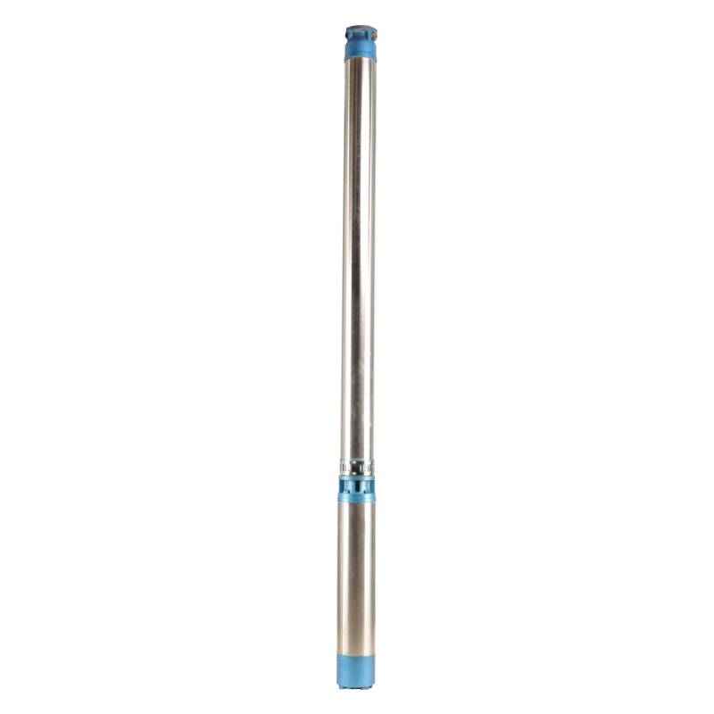
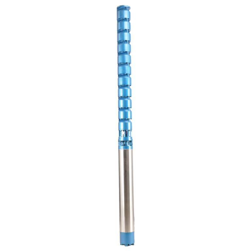
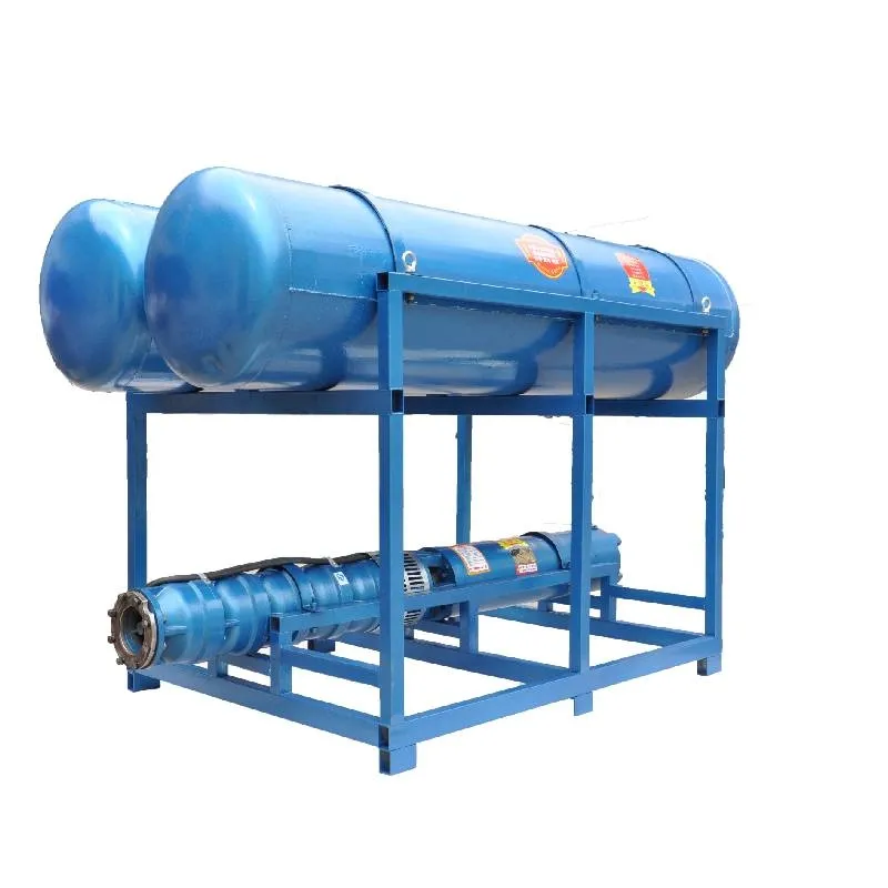
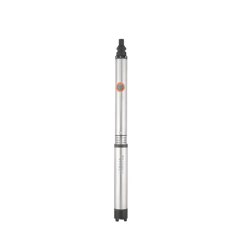
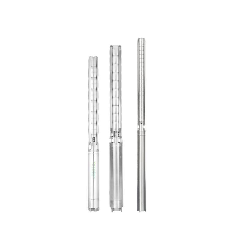
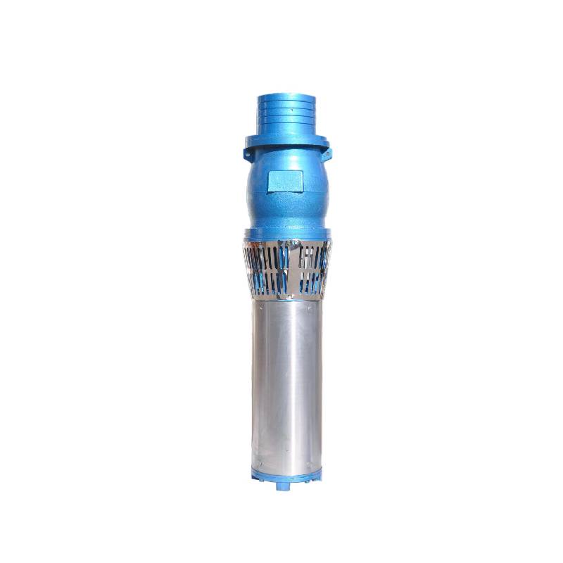
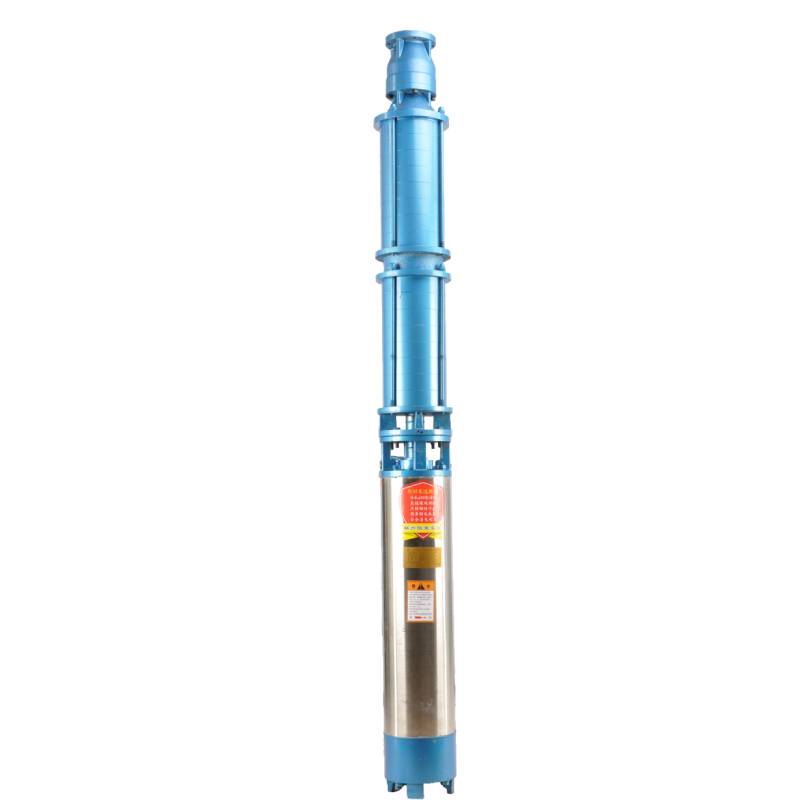
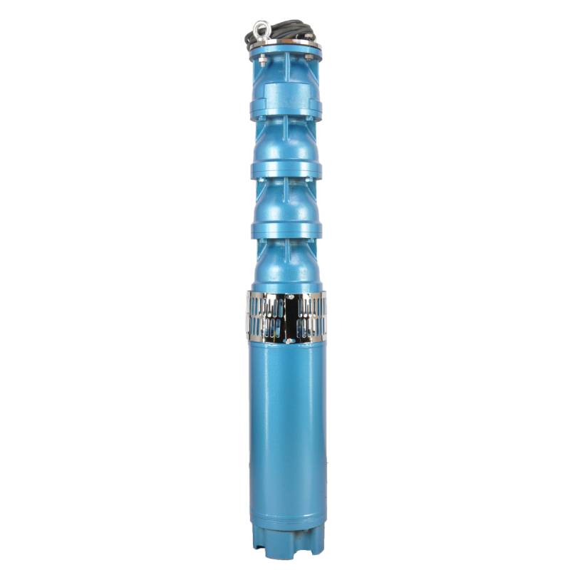
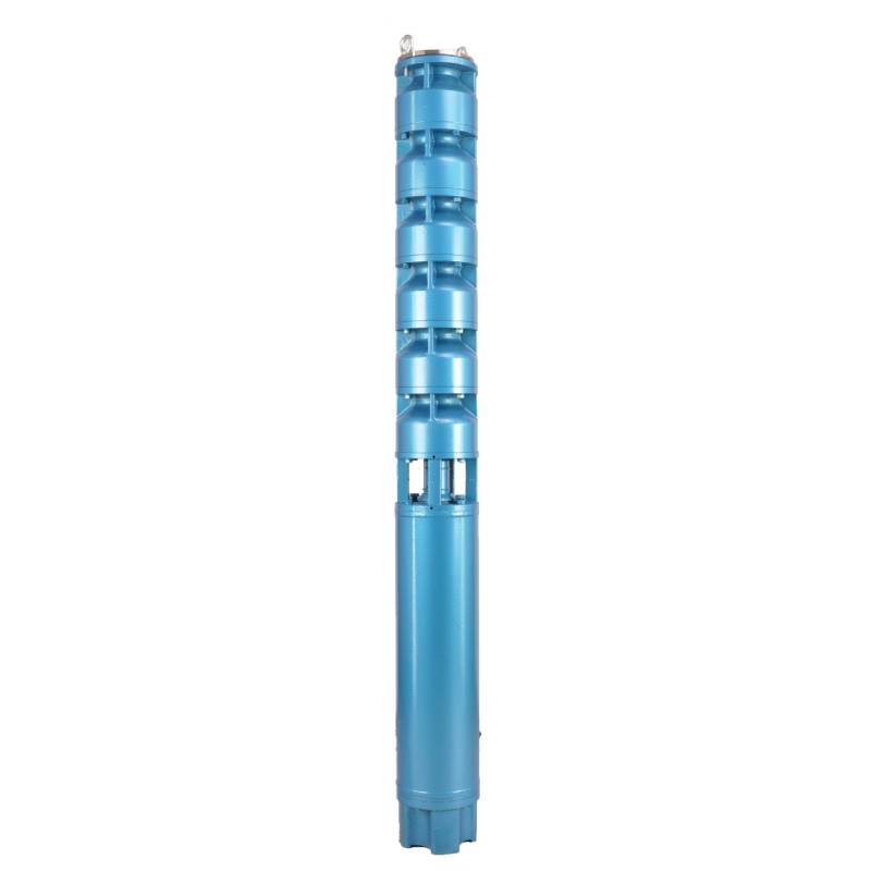
The variable frequency winding design ensures the motor's long-term smooth conversion operation between 1HZ-50HZ, energy saving and longer service life. This product stands out for its advanced technology and efficient performance, which can achieve energy-saving and environmentally friendly operation, while ensuring the stability and reliability of the motor for long-term use. Not only that, its design makes the product with a longer life, bringing more value to users. Whether in home applications or industrial fields, this motor can provide you with excellent performance to meet a variety of needs.
1,Power supply: three-phase AC 380V (tolerance + / - 5%), 50HZ (tolerance + / - 1%).
2, якість води:
(1) water temperature is not higher than 20 °C;
(2) вміст твердих домішок (масове співвідношення) не перевищує 0,01%;
(3) значення PH (pH) 6,5-8,5;
(4) вміст сірководню не перевищує 1,5 мг/л;
(5) вміст іонів хлориду не перевищує 400 мг/л.
3, the motor is a closed or water-filled wet structure, before use the submersible motor cavity must be full of clean water, to prevent false full, and then tighten the water injection, air release bolts, otherwise not allowed to use
4, the submersible pump must be completely submerged in the water, the diving depth is not greater than 70m, the bottom of the submersible pump from the bottom of the well is not less than 3m.
5, потік води в свердловині повинен бути в змозі задовольнити продуктивність води занурювального насоса та безперервну роботу, потік води занурювального насоса повинен контролюватися в 0,7 - 1,2 рази від номінального потоку.
6, колодязь повинен бути прямим, занурювальний насос не можна використовувати або скидати, лише вертикальне використання.
7, занурювальний насос повинен бути узгоджений з кабелем відповідно до вимог і зовнішнім пристроєм захисту від перевантаження.
8, the pump is strictly prohibited without water no-load test machine.
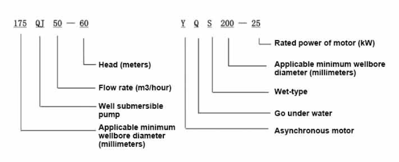
| Модель | Потік (м3/год) | Голова (м) |
Швидкість обертання (зміна/точка) |
Водяний насос(%) | Розетка діаметр (мм) |
Застосовується добре діаметр (мм) |
Оцінений потужність (кВт) |
Оцінений напруга (В) |
Оцінений струм (А) |
Моторна ефективність (%) | power factorcosφ | одиниця Максимальний радіальний розмір (мм) |
Зауваження | |||||||||
| 135QJ5-34 | 5 | 34 | 2850 | 40 | 135вище | 1.5 | 380 | 4.23 | 128 | |||||||||||||
| 135QJ5-51 | 51 | 2.2 | 6.03 | |||||||||||||||||||
| 135QJ5-68 | 68 | 3 | 8.01 | |||||||||||||||||||
| 135QJ5-85 | 85 | 4 | 10.53 | |||||||||||||||||||
| 135QJ5-102 | 102 | 5.5 | 14.1 | |||||||||||||||||||
| 135QJ5-119 | 119 | 5.5 | 14.1 | |||||||||||||||||||
| 135QJ5-240 | 240 | 11 | 26.28 | |||||||||||||||||||
| 135QJ5-280 | 5 | 280 | 2850 | 40 | 135вище | 13 | 380 | 30.87 | 128 | |||||||||||||
| 135QJ5-320 | 320 | 15 | 35.62 | |||||||||||||||||||
| 135QJ10-24 | 10 | 24 | 2850 | 50 | 135вище | 1.5 | 380 | 4.23 | 128 | |||||||||||||
| 135QJ10-32 | 32 | 2.2 | 6.03 | |||||||||||||||||||
| 135QJ10-48 | 48 | 3 | 8.01 | |||||||||||||||||||
| 135QJ10-56 | 56 | 4 | 10.53 | |||||||||||||||||||
| 135QJ10-72 | 72 | 5.5 | 14.1 | |||||||||||||||||||
| 135QJ10-80 | 80 | 5.5 | 14.1 | |||||||||||||||||||
| 135QJ10-104 | 104 | 7.5 | 19.0 | |||||||||||||||||||
| 135QJ10-120 | 120 | 7.5 | 19.0 | |||||||||||||||||||
| 135QJ10-136 | 136 | 9.2 | 22.7 | |||||||||||||||||||
| 135QJ10-180 | 180 | 11 | 26.28 | |||||||||||||||||||
| 135QJ10-210 | 210 | 13 | 30.87 | |||||||||||||||||||
| 135QJ10-240 | 240 | 15 | 35.62 | |||||||||||||||||||
| 135QJ10-300 | 300 | 18.5 | 43.12 | |||||||||||||||||||
| 135QJ15-36 | 15 | 36 | 2850 | 50 | 135вище | 2.2 | 380 | 6.03 | 128 | |||||||||||||
| 135QJ15-39 | 39 | 3 | 8.01 | |||||||||||||||||||
| 135QJ15-46 | 46 | 4 | 10.53 | |||||||||||||||||||
| 135QJ15-52 | 52 | 4 | 10.53 | |||||||||||||||||||
| 135QJ15-59 | 59 | 5.5 | 14.1 | |||||||||||||||||||
| 135QJ15-65 | 65 | 5.5 | 14.1 | |||||||||||||||||||
| 135QJ15-78 | 78 | 7.5 | 19.0 | |||||||||||||||||||
| 135QJ15-91 | 91 | 7.5 | 19.0 | |||||||||||||||||||
| 135QJ15-104 | 104 | 9.2 | 22.7 | |||||||||||||||||||
| 135QJ15-120 | 120 | 11 | 26.28 | |||||||||||||||||||
| 135QJ15-142 | 142 | 13 | 30.87 | |||||||||||||||||||
| 135QJ15-162 | 162 | 15 | 35.62 | |||||||||||||||||||
| 135QJ15-200 | 200 | 18.5 | 43.12 | |||||||||||||||||||
| 135QJ20-16 | 20 | 16 | 2850 | 50 | 135above | 2.2 | 380 | 6.03 | 128 | |||||||||||||
| 135QJ20-24 | 24 | 3 | 8.01 | |||||||||||||||||||
| 135QJ20-32 | 32 | 4 | 10.53 | |||||||||||||||||||
| 135QJ20-40 | 40 | 4 | 10.53 | |||||||||||||||||||
| 135QJ20-48 | 48 | 5.5 | 14.1 | |||||||||||||||||||
| 135QJ20-56 | 56 | 5.5 | 14.1 | |||||||||||||||||||
| 135QJ20-64 | 64 | 7.5 | 19.0 | |||||||||||||||||||
| 135QJ20-72 | 72 | 7.5 | 19.0 | |||||||||||||||||||
| 135QJ20-80135QJ20-100 | 80 | 9.2 | 22.7 | |||||||||||||||||||
| 100 | 11 | 26.28 | ||||||||||||||||||||
| 135QJ20-120 | 120 | 13 | 30.87 | |||||||||||||||||||
| 135QJ20-136 | 136 | 15 | 35.62 | |||||||||||||||||||
| 135QJ20-168135QJ25-12 | 168 | 18.5 | 43.12 | |||||||||||||||||||
| 25 | 12 | 2850 | 65 | 135вище | 2.2 | 380 | 6.03 | 128 | ||||||||||||||
| 135QJ25-18 | 18 | 3 | 8.01 | |||||||||||||||||||
| 135QJ25-24 | 24 | 4 | 10.53 | |||||||||||||||||||
| 135QJ25-30 | 30 | 4 | 10.53 | |||||||||||||||||||
| 135QJ25-36 | 36 | 5.5 | 14.1 | |||||||||||||||||||
| 135QJ25-48 | 48 | 7.5 | 19.0 | |||||||||||||||||||
| 135QJ25-60 | 60 | 9.2 | 22.7 | |||||||||||||||||||
| 135QJ25-82 | 82 | 11 | 26.28 | |||||||||||||||||||
| 135QJ25-97 | 97 | 13 | 30.87 | |||||||||||||||||||
| 135QJ25-110 | 110 | 15 | 35.62 | |||||||||||||||||||
| 135QJ25-130 | 130 | 18.5 | 43.12 | |||||||||||||||||||
| 135QJ32-24 | 32 | 24 | 2850 | 80 | 135вище | 4 | 380 | 10.53 | 128 | |||||||||||||
| 135QJ32-30 | 30 | 5.5 | 14.1 | |||||||||||||||||||
| 135QJ32-42 | 42 | 7.5 | 19.0 | |||||||||||||||||||
| 135QJ32-54 | 54 | 9.2 | 22.7 | |||||||||||||||||||
| 135QJ32-68 | 68 | 11 | 26.28 | |||||||||||||||||||
| 135QJ32-80 | 80 | 13 | 30.87 | |||||||||||||||||||
| 135QJ32-92 | 92 | 15 | 35.62 | |||||||||||||||||||
| 135QJ32-104 | 104 | 18.5 | 43.12 | |||||||||||||||||||
| 135QJ40-46 | 40 | 46 | 2850 | 80 | 135вище | 11 | 380 | 26.28 | 128 | |||||||||||||
| 135QJ40-54 | 54 | 13 | 30.87 | |||||||||||||||||||
| 135QJ40-62 | 62 | 15 | 35.62 | |||||||||||||||||||
| 135QJ40-84 | 84 | 18.5 | 43.12 | |||||||||||||||||||
1, well submersible pump for clean water pump, prohibit the new well, pumping sediment and muddy water,
2, well water pump voltage grade of 380/50HZ, the use of other voltage grades of submersible motors need to be customized. The underground cable must use waterproof cable, must be equipped with starting equipment, such as distribution box, start not ready should have commonly used motor comprehensive protection function, such as short circuit overload protection, phase protection, undervoltage protection, grounding protection, idling protection, in case of abnormal conditions, the protection device should be timely action trip.
3, the installation and use of the pump must be reliably grounded, prohibit the push and pull switch when the hands and feet are wet, the installation and maintenance of the pump must be cut off the power supply, the use of the pump place to set up "to prevent electric shock" obvious signs:
4, down the well or before installation, the motor cavity must be filled with distilled water or non-corrosive clean cold boiling water, tighten the / water bolt, the pump on the ground test run, must be to the pump chamber water lubrication rubber bearings, instant start not more than a second, see whether the steering is the same as the steering instructions. When the pump is upright, pay attention to safety, prevent overturning injury.
5, суворо відповідно до положень підйому насоса, діапазону витрат, щоб запобігти низькому потоку або високому підйому, насосна сила, упорний підшипник та інші частини зносу, перевантаження двигуна спалено 6, після того, як насос вниз свердловини, вимірювання опору ізоляції двигуна до землі не повинно бути менше 100 М, після запуску спостерігати за напругою та струмом, перевіряти ізоляцію обмотки двигуна, чи відповідає вимогам; Якщо температура місця зберігання насоса нижче точки замерзання, слід висушити воду в порожнині двигуна, запобігти пошкодженню порожнини двигуна водяним льодом, спричиненим низькою температурою.
The pump parts are mainly composed of pump shaft, impeller, shunt shell, rubber bearing, check valve body (optional) and other components. The motor parts are mainly composed of base, pressure regulating diaphragm, thrust bearing, thrust plate, lower guide bearing seat, stator, rotor, upper guide bearing seat, sand discharging ring, water inlet section, and lead cable.
До основних особливостей продукту відносяться:
The main characteristic of the product is that the pump is a water-immersed three-phase asynchronous motor, and the motor cavity is full of water for cooling the motor and lubricating the bearing. The pressure regulating diaphragm at the bottom of the motor is used to adjust the expansion-contraction pressure difference of the water inside the body caused by the change of temperature. At the same time, in order to prevent the sand particles in the well water from entering the motor, two oil seals are installed at the end of the motor shaft, and the sand discharging ring is installed to form a sand control structure. In order to prevent the pump shaft from beating when starting up, the pump shaft and the motor shaft are connected by a coupling, and the thrust bearing is installed at the bottom of the motor. In addition, the motor and the pump bearing are water-lubricated, and the stator winding of the motor uses high-quality submersible motor winding to ensure high insulation performance. The overall design is made of computer CAD, with simple structure and superior technical performance.

(1) Підготовка перед установкою:
1. Перевірте, чи відповідає занурювальний насос умовам використання та обсягу, зазначеним у посібнику.
2. Використовуючи важкий об’єкт діаметром, що дорівнює максимальному зовнішньому діаметру занурювального насоса, виміряйте, чи внутрішній діаметр стовбура свердловини підходить для погружного насоса, і виміряйте, чи відповідає глибина свердловини вимогам до встановлення.
3. Перевірте чи чистий стовбур свердловини і чи не каламутна вода в свердловині. Ніколи не використовуйте занурювальний електричний насос для промивання бруду та піску насоса Welor, щоб уникнути передчасного пошкодження занурювального електричного насоса.
4. Перевірте, чи підходить положення монтажного хомута бурової головки та чи може він витримати якість усього блоку
5. Перевірте, чи компоненти занурювального насоса укомплектовані та встановлені належним чином відповідно до монтажної схеми в посібнику. Зніміть сітку фільтра та поверніть муфту, щоб перевірити, чи вона гнучко обертається
6. Відкрутіть гвинт подачі води та заповніть порожнину двигуна чистою водою, яка не викликає корозії (зверніть увагу, обов’язково наповніть її), а потім затягніть гвинт подачі води. Після 12 годин впорскування води опір ізоляції двигуна не повинен бути меншим за 150 М Q при вимірюванні за допомогою струшувального столу 500 В.
7. Cable joint, cut off a 120mm rubber sleeve from one end of the outgoing cable and the matching cable with an electrician's knifethen stagger the length of the three core wires in a stepped shape, peel off a 20mm copper core, scrape of the oxide layer on theoutside of the copper wire with a knife or sand cloth, and insert the two connected wire ends in palirs.After tying the layer tightly with fine copper wire, solder it thoroughly and firmly, and sand of any. burrs on the surface. Then, forthe three joints, use polyvester insulation tape to wrap them in a semi stacked manner for three lavers. Wrap the two ends of thewrapping layer tightywith nyion thread,and then use a semi stacked method to wrap the tape for three layers. Wrap the outellayer with high-pressure insulation tape for three layers. Finally, fold the threestrands together and repeatedly wrap them for fivelayers with high-pressure tape. Each layer must be tightly tied, and the interlayer joints must be tight and fimm to prevent water frompenetrating and damaging the insulation, After wrapping, soak in water at room temperature of 20 ’c for 12 hours, and measurethe insulation resistance with a shaking table, which should not be less than 100M Ω
Схема процесу підключення кабелю, що додається, така:
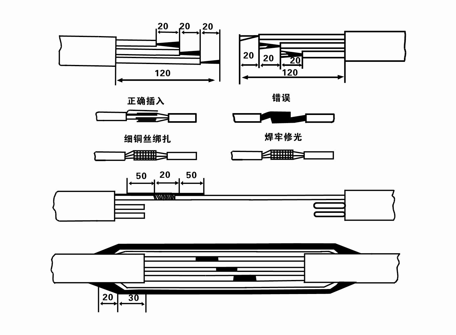
8. За допомогою мультиметра перевірте, чи підключені трифазні дроти і чи приблизно збалансований опір постійному струму.
9. Перевірте, чи не перевантажена ланцюг і потужність трансформатора, а потім підключіть вимикач захисту від перевантаження або пускове обладнання. Див. Таблицю 2 для конкретних моделей, а потім налийте відро води у водяний насос із вихідного отвору водяного насоса, щоб змастити гумові підшипники в насосі, а потім поставте занурювальний електричний насос вертикально та стійко. Запуск (не більше однієї секунди) і перевірте, чи напрям рульового керування відповідає кермовому знаку. Якщо ні, поміняйте місцями будь-які два роз’єми трифазного кабелю. Потім встановіть фільтр і підготуйтеся до спуску в колодязь. Якщо використовується в особливих випадках (таких як канави, канави, річки, ставки, ставки тощо), електронасос повинен бути надійно заземлений.
(2) Інсталяційне обладнання та інструменти:
1. Одна пара вантажопідйомних ланцюгів більше двох тонн.
2. Штатив висотою по вертикалі не менше чотирьох метрів.
3. Дві підвісні мотузки (троси), які витримують вагу понад одну тонну (можуть витримувати вагу повного комплекту водяних насосів).
4. Встановити дві пари затискачів (шпон).
5. Ключі, молотки, викрутки, електроінструменти та ін.
(3) Установка електричного насоса:
1. Схема монтажу занурювального електричного насоса показана на малюнку 2. Конкретні розміри для встановлення наведені в таблиці 3 «Перелік установочних розмірів занурювального електричного насоса».
2. Занурювальні електричні насоси з напором менше 30 метрів можна підняти безпосередньо в колодязь за допомогою шлангів і дротяних канатів або інших пенькових мотузок, які можуть витримати повну вагу всієї машини, водопровідних труб і води в трубах.
3. Для насосів з напором більше 30 метрів використовуються сталеві труби, послідовність монтажу наступна:
①Використовуйте затискач, щоб затиснути верхній кінець частини водяного насоса (двигун і водяний насос наразі з’єднані), підніміть його за допомогою підвісного ланцюга та повільно прив’яжіть до колодязя, доки не надягнете затискач на гирлі свердловини та не зніміть підвісний ланцюг.
② Використовуйте іншу пару затискачів, щоб затиснути трубу, підніміть її за допомогою підвісного ланцюга на 15 см від фланця та повільно опустіть. Між фланцем труби та фланцем насоса Вставте гумову прокладку на місце та рівномірно затягніть трубу та насос болтами, гайками та пружинними шайбами.
③ Злегка підніміть занурювальний насос, зніміть хомут на верхньому кінці водяного насоса, міцно прив’яжіть кабель до водопровідної труби пластиковою стрічкою та повільно прив’яжіть його, доки хомут не буде встановлено на гирлі свердловини.
④Використовуйте той самий метод, щоб прив’язати всі водопровідні труби до колодязя.
⑤Після того, як вихідний кабель під’єднано до перемикача керування, його підключають до трифазного джерела живлення.
(4) На що слід звернути увагу під час встановлення:
1. Якщо під час процесу перекачування виявлено заклинювання, поверніть або потягніть водопровідну трубу, щоб подолати точку заклинювання. Якщо різні заходи все ще не працюють, будь ласка, не опускайте насос силою, щоб уникнути пошкодження занурювального електричного насоса та колодязя.
2. Під час монтажу гумову прокладку слід помістити на фланець кожної труби та рівномірно затягнути.
3. Коли водяний насос опускається в колодязь, його слід розташувати в середині колодязьної труби, щоб запобігти довгому натисканню насоса на стінку колодязя, що спричиняє вібрацію насоса, а двигун – підмітання та горіння. .
4. Визначте глибину залягання водяного насоса на дно свердловини відповідно до умов текучого піску та мулу свердловини. Не заривайте насос у багнюку. Відстань від водяного насоса до дна колодязя, як правило, становить не менше 3 метрів (див. рис. 2).
5. Глибина входу води водяного насоса повинна бути не менше 1-1,5 метра від динамічного рівня води до вузла водозабору (див. рисунок 2). Інакше можна легко пошкодити підшипники водяного насоса.
6. Підйом водяного насоса не може бути занадто низьким. В іншому випадку необхідно встановити засувний клапан на водопровідному трубопроводі гирла свердловини, щоб контролювати потік насоса при номінальній точці потоку, щоб запобігти перевантаженню та згорянню двигуна через великі витрати.
7. Коли водяний насос працює, вихід води повинен бути безперервним і рівномірним, струм повинен бути стабільним (за номінальних умов роботи, як правило, не більше 10% від номінального струму), і не повинно бути вібрації або шуму. Якщо є будь-яка несправність, машину слід зупинити, щоб з’ясувати причину та усунути її.
8. Під час встановлення зверніть увагу на налаштування дроту заземлення двигуна (див. Малюнок 2). Якщо водопровід є сталевою трубою, виведіть її від гирлового хомута; якщо водопровідна труба пластикова, проведіть її від позначки заземлення електричного насоса.
- 1.After the submersible pump is installed, check the insulation resistance and three-phase conduction from the switch again, check whether the instrument and the connection of the start equipment are wrong, if there is no problem, the trial machine can be started, and after the start, observe whether the indicator readings of the instrument exceed the rated voltage and current specified on the nameplate, observe whether the pump has noise and vibration phenomenon, and put into operation if everything is normal.
- 2. After the first operation of the pump for four hours, the motor should be stopped to test the thermal insulation resistance quickly, and its value should not be less than 0.5 megaohm.
- 3. After the pump is stopped, it should be started after five minutes to prevent the water column in the pipe from being completely reflowed and causing the motor to burn out due to excessive current.
- 4. Our pump is designed to provide efficient, reliable and lasting pumping solutions.After normal operation, in order to prolong the service life of the pump, it is necessary to check the power supply voltage, running current and insulation resistance regularly to ensure that they are normal.
- If the following conditions are found, the machine should be shut down immediately to eliminate the fault:
- - the current exceeds 20% under the rated working conditions;
- - the dynamic water level drops to the inlet section, resulting in intermittent drainage;
- - the submersible pump vibrates violently or emits noisy sounds;
- - the power supply voltage is lower than 340 volts;
- - one phase of a fuse is blown out;
- - the water pipe is damaged;
- - the thermal insulation resistance of the motor to the ground is less than 0.5 megaohm.
- The steps of disassembling the unit include unlocking the cable holder, taking off the pipe part, removing the line protection plate, rotating the drain screw and emptying all the water in the motor chamber, taking out the filter and loosening the screw of the coupling fixed to the motor shaft.Unscrew the bolt connecting the water inlet section and the motor, and separate the pump and the motor (note that the unit should be placed horizontally when separating to prevent the bending of the pump shaft).
- 5. The disassembly sequence of the pump includes: water inlet part, impeller, shunt shell, impeller, check valve body.When removing the impeller, use a special tool to loosen the cone sleeve fixing the impeller.During the disassembly process, avoid bending the pump shaft and damaging various parts.The disassembly process of the motor includes: placing the motor on the platform, and then removing the nuts on the studs, base, shaft head lock nut, thrust plate, key, lower guide rail, bearing seat and bolt from the bottom of the motor, then removing the rotor (be careful not to damage the winding), and finally removing the connecting parts and upper guide bearing seat. Before assembling the unit, it is necessary to clean the rust and dirt of each part, and apply sealant on each mating surface and fastener, and then assemble it in the opposite order of disassembly.After assembly, the coupling should be flexibly rotated, and then the filter should be put on to test the machine. Our pump products are designed to provide superior performance and reliability to meet your pumping needs.
- 6. Submersible pumps operating every year, or less than a year of operation but the submersible time has reached two years, should be taken out of the well according to the 5th dismantled maintenance, replacement of worn parts.
1, вилийте воду з порожнини двигуна (особливо взимку, щоб запобігти замерзанню двигуна) і добре зав’яжіть кабель.
2, store in an indoor room without corrosive substances and gases, with a temperature below 40 °C.
3, при тривалому використанні слід звернути увагу на запобігання іржі занурювальних насосів.
- крильчатка
- Втулка валу
- Гумова втулка валу
- Ущільнювальне кільце
01 Водозабір глибокої свердловини
02 Багатоповерховий водопровід
03 гірський водопровід
04 водопровідна башта
05 Сільськогосподарське зрошення
06 зрошення саду
07 річковий водозабір
08 побутова вода

