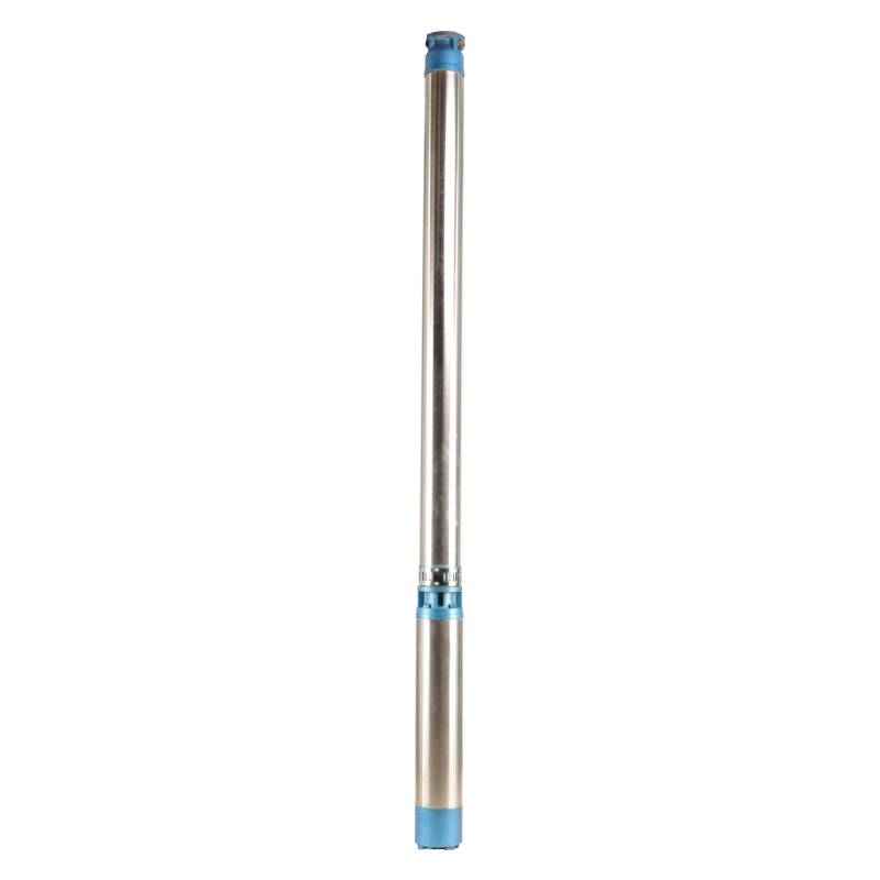
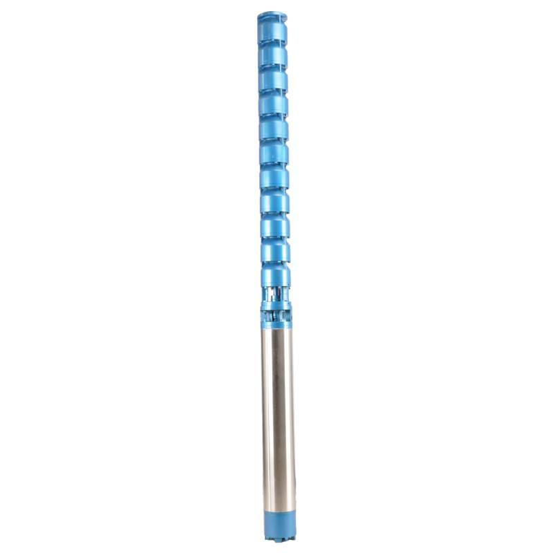
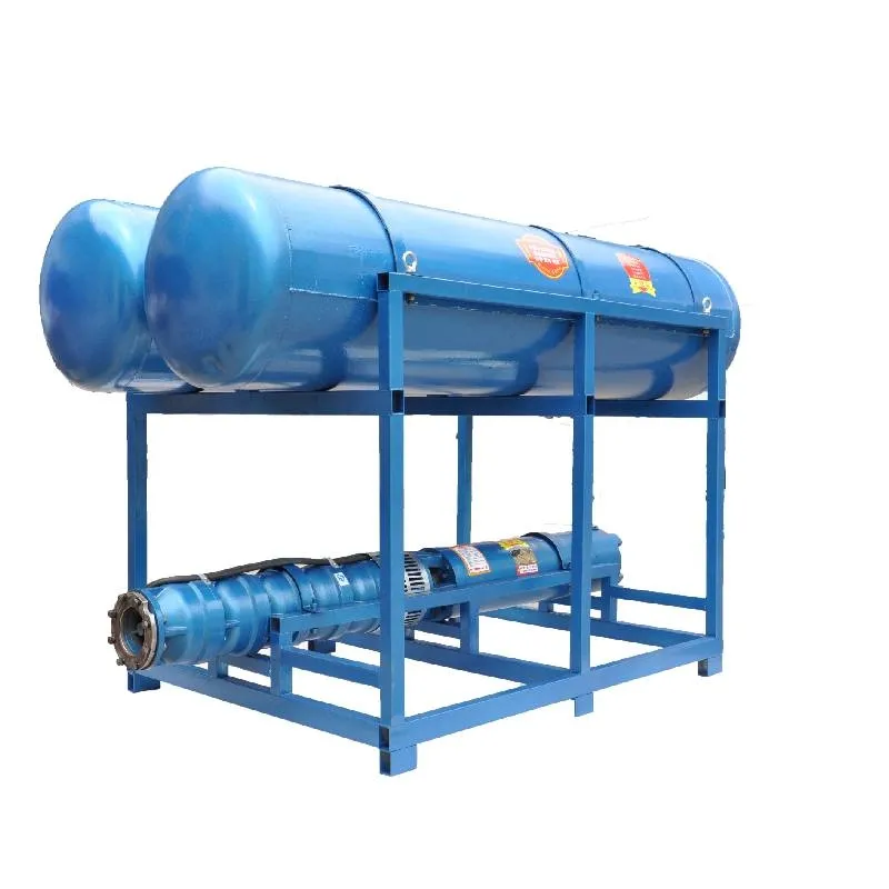
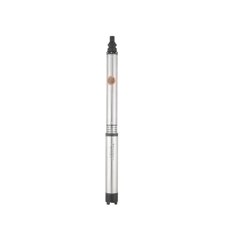
The variable frequency winding design ensures the motor's long-term smooth conversion operation between 1HZ-50HZ, energy saving and longer service life. This product stands out for its advanced technology and efficient performance, which can achieve energy-saving and environmentally friendly operation, while ensuring the stability and reliability of the motor for long-term use. Not only that, its design makes the product with a longer life, bringing more value to users. Whether in home applications or industrial fields, this motor can provide you with excellent performance to meet a variety of needs.
1,Power supply: three-phase AC 380V (tolerance + / - 5%), 50HZ (tolerance + / - 1%).
2, qualitat de l'aigua:
(1) water temperature is not higher than 20 °C;
(2) el contingut d'impureses sòlides (proporció de massa) no és superior al 0,01%;
(3) valor de pH (pH) 6,5-8,5;
(4) el contingut de sulfur d'hidrogen no és superior a 1,5 mg/L;
(5) El contingut d'ions clorur no és superior a 400 mg/L.
3, the motor is a closed or water-filled wet structure, before use the submersible motor cavity must be full of clean water, to prevent false full, and then tighten the water injection, air release bolts, otherwise not allowed to use
4, the submersible pump must be completely submerged in the water, the diving depth is not greater than 70m, the bottom of the submersible pump from the bottom of the well is not less than 3m.
5, el cabal d'aigua del pou ha de poder satisfer la sortida d'aigua de la bomba submergible i el funcionament continu, la sortida d'aigua de la bomba submergible s'ha de controlar entre 0,7 i 1,2 vegades el cabal nominal.
6, el pou ha de ser recte, la bomba submergible no es pot utilitzar ni abocar, només ús vertical.
7, la bomba submergible s'ha de combinar amb el cable segons els requisits i el dispositiu extern de protecció contra sobrecàrregues.
8, the pump is strictly prohibited without water no-load test machine.
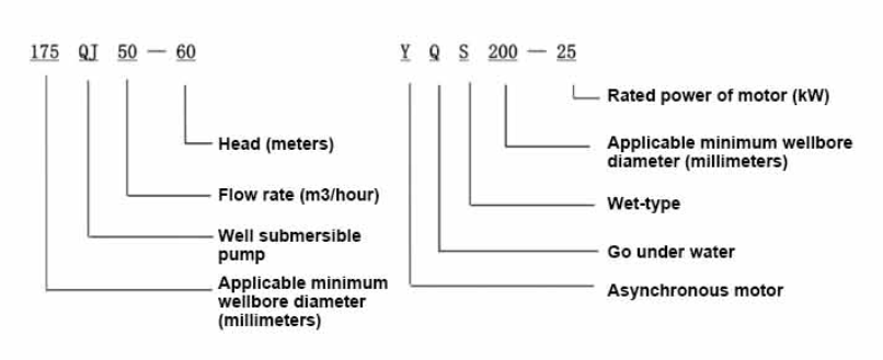
| Model | Caudal (m3/h) | Cap (m) |
Velocitat de gir (canvi/punt) |
Bomba d'aigua(%) | Outlet diàmetre (mm) |
Aplicable bé diàmetre (mm) |
Valorat potència (KW) |
Valorat tensió (V) |
Valorat corrent (A) |
Eficiència motora (%) | power factorcosφ | Unitat Mida màxima radial (mm) |
Observació | |||||||||
| 135QJ5-34 | 5 | 34 | 2850 | 40 | 135a dalt | 1.5 | 380 | 4.23 | 128 | |||||||||||||
| 135QJ5-51 | 51 | 2.2 | 6.03 | |||||||||||||||||||
| 135QJ5-68 | 68 | 3 | 8.01 | |||||||||||||||||||
| 135QJ5-85 | 85 | 4 | 10.53 | |||||||||||||||||||
| 135QJ5-102 | 102 | 5.5 | 14.1 | |||||||||||||||||||
| 135QJ5-119 | 119 | 5.5 | 14.1 | |||||||||||||||||||
| 135QJ5-240 | 240 | 11 | 26.28 | |||||||||||||||||||
| 135QJ5-280 | 5 | 280 | 2850 | 40 | 135a dalt | 13 | 380 | 30.87 | 128 | |||||||||||||
| 135QJ5-320 | 320 | 15 | 35.62 | |||||||||||||||||||
| 135QJ10-24 | 10 | 24 | 2850 | 50 | 135a dalt | 1.5 | 380 | 4.23 | 128 | |||||||||||||
| 135QJ10-32 | 32 | 2.2 | 6.03 | |||||||||||||||||||
| 135QJ10-48 | 48 | 3 | 8.01 | |||||||||||||||||||
| 135QJ10-56 | 56 | 4 | 10.53 | |||||||||||||||||||
| 135QJ10-72 | 72 | 5.5 | 14.1 | |||||||||||||||||||
| 135QJ10-80 | 80 | 5.5 | 14.1 | |||||||||||||||||||
| 135QJ10-104 | 104 | 7.5 | 19.0 | |||||||||||||||||||
| 135QJ10-120 | 120 | 7.5 | 19.0 | |||||||||||||||||||
| 135QJ10-136 | 136 | 9.2 | 22.7 | |||||||||||||||||||
| 135QJ10-180 | 180 | 11 | 26.28 | |||||||||||||||||||
| 135QJ10-210 | 210 | 13 | 30.87 | |||||||||||||||||||
| 135QJ10-240 | 240 | 15 | 35.62 | |||||||||||||||||||
| 135QJ10-300 | 300 | 18.5 | 43.12 | |||||||||||||||||||
| 135QJ15-36 | 15 | 36 | 2850 | 50 | 135a dalt | 2.2 | 380 | 6.03 | 128 | |||||||||||||
| 135QJ15-39 | 39 | 3 | 8.01 | |||||||||||||||||||
| 135QJ15-46 | 46 | 4 | 10.53 | |||||||||||||||||||
| 135QJ15-52 | 52 | 4 | 10.53 | |||||||||||||||||||
| 135QJ15-59 | 59 | 5.5 | 14.1 | |||||||||||||||||||
| 135QJ15-65 | 65 | 5.5 | 14.1 | |||||||||||||||||||
| 135QJ15-78 | 78 | 7.5 | 19.0 | |||||||||||||||||||
| 135QJ15-91 | 91 | 7.5 | 19.0 | |||||||||||||||||||
| 135QJ15-104 | 104 | 9.2 | 22.7 | |||||||||||||||||||
| 135QJ15-120 | 120 | 11 | 26.28 | |||||||||||||||||||
| 135QJ15-142 | 142 | 13 | 30.87 | |||||||||||||||||||
| 135QJ15-162 | 162 | 15 | 35.62 | |||||||||||||||||||
| 135QJ15-200 | 200 | 18.5 | 43.12 | |||||||||||||||||||
| 135QJ20-16 | 20 | 16 | 2850 | 50 | 135above | 2.2 | 380 | 6.03 | 128 | |||||||||||||
| 135QJ20-24 | 24 | 3 | 8.01 | |||||||||||||||||||
| 135QJ20-32 | 32 | 4 | 10.53 | |||||||||||||||||||
| 135QJ20-40 | 40 | 4 | 10.53 | |||||||||||||||||||
| 135QJ20-48 | 48 | 5.5 | 14.1 | |||||||||||||||||||
| 135QJ20-56 | 56 | 5.5 | 14.1 | |||||||||||||||||||
| 135QJ20-64 | 64 | 7.5 | 19.0 | |||||||||||||||||||
| 135QJ20-72 | 72 | 7.5 | 19.0 | |||||||||||||||||||
| 135QJ20-80135QJ20-100 | 80 | 9.2 | 22.7 | |||||||||||||||||||
| 100 | 11 | 26.28 | ||||||||||||||||||||
| 135QJ20-120 | 120 | 13 | 30.87 | |||||||||||||||||||
| 135QJ20-136 | 136 | 15 | 35.62 | |||||||||||||||||||
| 135QJ20-168135QJ25-12 | 168 | 18.5 | 43.12 | |||||||||||||||||||
| 25 | 12 | 2850 | 65 | 135a dalt | 2.2 | 380 | 6.03 | 128 | ||||||||||||||
| 135QJ25-18 | 18 | 3 | 8.01 | |||||||||||||||||||
| 135QJ25-24 | 24 | 4 | 10.53 | |||||||||||||||||||
| 135QJ25-30 | 30 | 4 | 10.53 | |||||||||||||||||||
| 135QJ25-36 | 36 | 5.5 | 14.1 | |||||||||||||||||||
| 135QJ25-48 | 48 | 7.5 | 19.0 | |||||||||||||||||||
| 135QJ25-60 | 60 | 9.2 | 22.7 | |||||||||||||||||||
| 135QJ25-82 | 82 | 11 | 26.28 | |||||||||||||||||||
| 135QJ25-97 | 97 | 13 | 30.87 | |||||||||||||||||||
| 135QJ25-110 | 110 | 15 | 35.62 | |||||||||||||||||||
| 135QJ25-130 | 130 | 18.5 | 43.12 | |||||||||||||||||||
| 135QJ32-24 | 32 | 24 | 2850 | 80 | 135a dalt | 4 | 380 | 10.53 | 128 | |||||||||||||
| 135QJ32-30 | 30 | 5.5 | 14.1 | |||||||||||||||||||
| 135QJ32-42 | 42 | 7.5 | 19.0 | |||||||||||||||||||
| 135QJ32-54 | 54 | 9.2 | 22.7 | |||||||||||||||||||
| 135QJ32-68 | 68 | 11 | 26.28 | |||||||||||||||||||
| 135QJ32-80 | 80 | 13 | 30.87 | |||||||||||||||||||
| 135QJ32-92 | 92 | 15 | 35.62 | |||||||||||||||||||
| 135QJ32-104 | 104 | 18.5 | 43.12 | |||||||||||||||||||
| 135QJ40-46 | 40 | 46 | 2850 | 80 | 135a dalt | 11 | 380 | 26.28 | 128 | |||||||||||||
| 135QJ40-54 | 54 | 13 | 30.87 | |||||||||||||||||||
| 135QJ40-62 | 62 | 15 | 35.62 | |||||||||||||||||||
| 135QJ40-84 | 84 | 18.5 | 43.12 | |||||||||||||||||||
1, well submersible pump for clean water pump, prohibit the new well, pumping sediment and muddy water,
2, well water pump voltage grade of 380/50HZ, the use of other voltage grades of submersible motors need to be customized. The underground cable must use waterproof cable, must be equipped with starting equipment, such as distribution box, start not ready should have commonly used motor comprehensive protection function, such as short circuit overload protection, phase protection, undervoltage protection, grounding protection, idling protection, in case of abnormal conditions, the protection device should be timely action trip.
3, the installation and use of the pump must be reliably grounded, prohibit the push and pull switch when the hands and feet are wet, the installation and maintenance of the pump must be cut off the power supply, the use of the pump place to set up "to prevent electric shock" obvious signs:
4, down the well or before installation, the motor cavity must be filled with distilled water or non-corrosive clean cold boiling water, tighten the / water bolt, the pump on the ground test run, must be to the pump chamber water lubrication rubber bearings, instant start not more than a second, see whether the steering is the same as the steering instructions. When the pump is upright, pay attention to safety, prevent overturning injury.
5, estrictament d'acord amb les disposicions de l'elevació de la bomba, rang d'ús de flux, per evitar la força de bombament de baix cabal o elevació elevada, el coixinet d'empenta i altres parts del desgast, la sobrecàrrega del motor es crema 6, després de la bomba avall el pou, la mesura de la resistència d'aïllament del motor a terra no ha de ser inferior a 100 M, després de l'inici per observar la tensió i el corrent, comproveu l'aïllament del bobinat del motor, ja sigui d'acord amb els requisits; La temperatura de la ubicació d'emmagatzematge de la bomba si és inferior al punt de congelació, s'ha d'assecar l'aigua de la cavitat del motor, evitar els danys del gel de la cavitat del motor causats per la baixa temperatura.
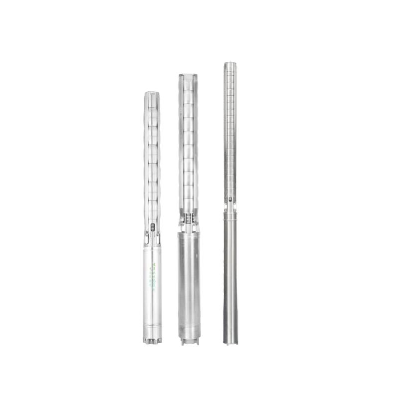
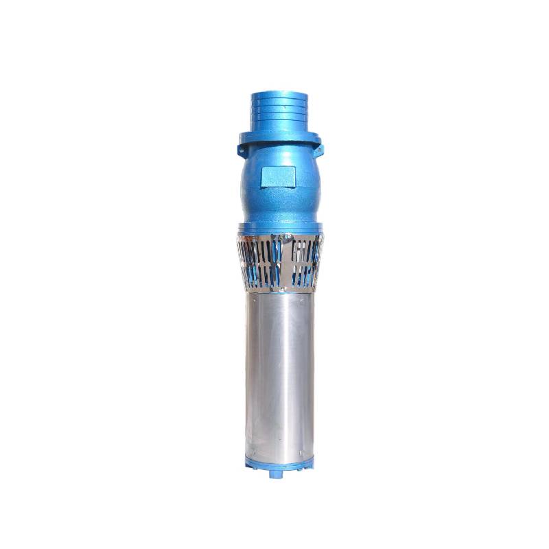
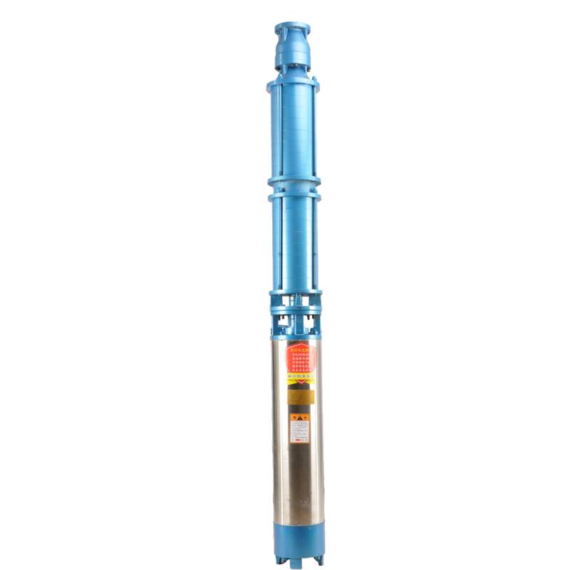
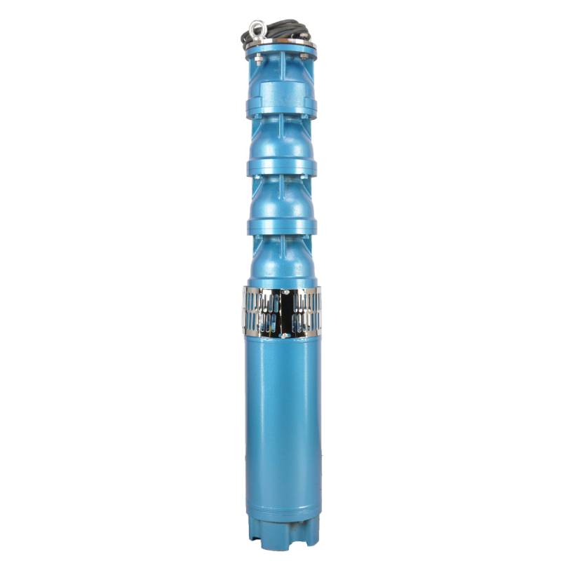
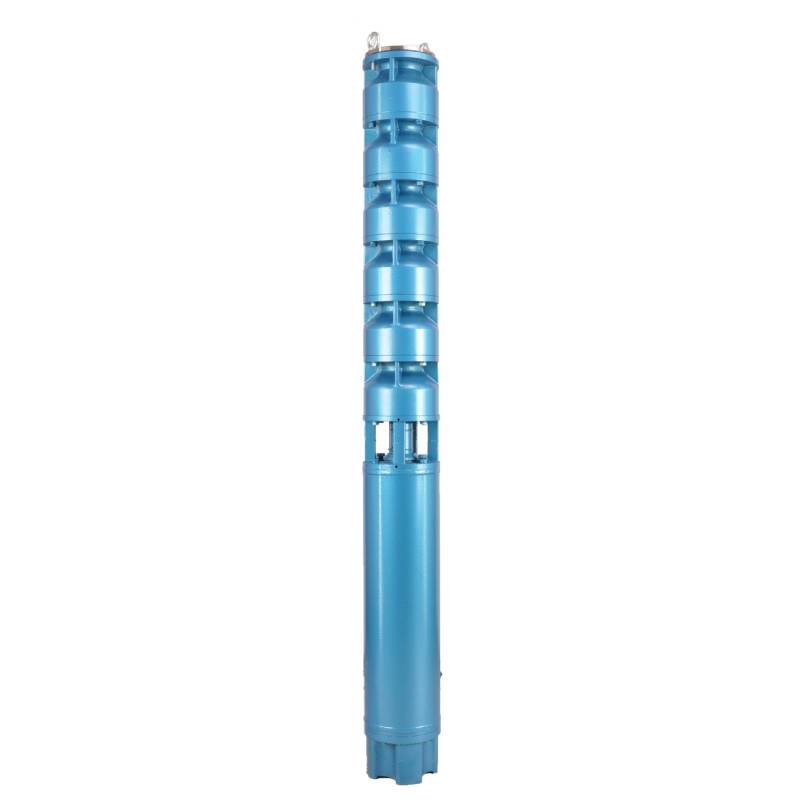
The pump parts are mainly composed of pump shaft, impeller, shunt shell, rubber bearing, check valve body (optional) and other components. The motor parts are mainly composed of base, pressure regulating diaphragm, thrust bearing, thrust plate, lower guide bearing seat, stator, rotor, upper guide bearing seat, sand discharging ring, water inlet section, and lead cable.
Les principals característiques del producte inclouen:
The main characteristic of the product is that the pump is a water-immersed three-phase asynchronous motor, and the motor cavity is full of water for cooling the motor and lubricating the bearing. The pressure regulating diaphragm at the bottom of the motor is used to adjust the expansion-contraction pressure difference of the water inside the body caused by the change of temperature. At the same time, in order to prevent the sand particles in the well water from entering the motor, two oil seals are installed at the end of the motor shaft, and the sand discharging ring is installed to form a sand control structure. In order to prevent the pump shaft from beating when starting up, the pump shaft and the motor shaft are connected by a coupling, and the thrust bearing is installed at the bottom of the motor. In addition, the motor and the pump bearing are water-lubricated, and the stator winding of the motor uses high-quality submersible motor winding to ensure high insulation performance. The overall design is made of computer CAD, with simple structure and superior technical performance.

(1) Preparació abans de la instal·lació:
1. Comproveu si la bomba submergible compleix les condicions d'ús i l'abast especificats al manual.
2. Utilitzant un objecte pesat amb un diàmetre igual al diàmetre exterior màxim de la bomba submergible, mesura si el diàmetre interior del pou pot adaptar-se a la bomba submergible i mesura si la profunditat del pou compleix els requisits d'instal·lació.
3. Comproveu si el pou està net i si l'aigua del pou està tèrbol. No utilitzeu mai una bomba elèctrica submergible per rentar el fang i l'aigua de sorra de la bomba Welor per evitar danys prematurs a la bomba elèctrica submergible.
4. Comproveu si la posició de la pinça d'instal·lació del capçal és adequada i si pot suportar la qualitat de tota la unitat
5. Comproveu si els components de la bomba submergible estan complets i instal·lats correctament segons el diagrama de muntatge del manual. Traieu la pantalla del filtre i gireu l'acoblament per veure si gira amb flexibilitat.
6. Desenrosqueu el cargol d'aigua i ompliu la cavitat del motor amb aigua neta i no corrosiva (nota: assegureu-vos d'omplir-lo), a continuació, premeu el cargol d'aigua. Després de 12 hores d'injecció d'aigua, la resistència d'aïllament del motor no ha de ser inferior a 150 M Q quan es mesura amb una taula de sacsejada de 500 V.
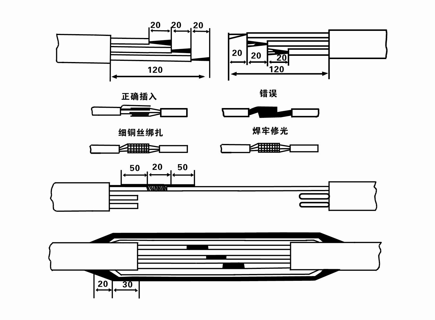
7. Cable joint, cut off a 120mm rubber sleeve from one end of the outgoing cable and the matching cable with an electrician's knifethen stagger the length of the three core wires in a stepped shape, peel off a 20mm copper core, scrape of the oxide layer on theoutside of the copper wire with a knife or sand cloth, and insert the two connected wire ends in palirs.After tying the layer tightly with fine copper wire, solder it thoroughly and firmly, and sand of any. burrs on the surface. Then, forthe three joints, use polyvester insulation tape to wrap them in a semi stacked manner for three lavers. Wrap the two ends of thewrapping layer tightywith nyion thread,and then use a semi stacked method to wrap the tape for three layers. Wrap the outellayer with high-pressure insulation tape for three layers. Finally, fold the threestrands together and repeatedly wrap them for fivelayers with high-pressure tape. Each layer must be tightly tied, and the interlayer joints must be tight and fimm to prevent water frompenetrating and damaging the insulation, After wrapping, soak in water at room temperature of 20 ’c for 12 hours, and measurethe insulation resistance with a shaking table, which should not be less than 100M Ω
El diagrama de procés de cablejat del cable adjunt és el següent:
8. Utilitzeu un multímetre per comprovar si els cables trifàsics estan connectats i si la resistència de CC està aproximadament equilibrada.
9. Comproveu si el circuit i la capacitat del transformador estan sobrecarregats i, a continuació, connecteu l'interruptor de protecció de sobrecàrrega o l'equip d'arrencada. Consulteu la taula 2 per a models específics i, a continuació, aboqueu una galleda d'aigua a la bomba d'aigua des de la sortida de la bomba d'aigua per lubricar els coixinets de goma de la bomba i, a continuació, col·loqueu la bomba elèctrica submergible en posició vertical i constant. Inicieu (no més d'un segon) i comproveu si la direcció de la direcció és coherent amb el senyal de direcció. Si no, intercanvieu dos connectors qualsevol del cable trifàsic. A continuació, instal·leu el filtre i prepareu-vos per baixar pel pou. Si s'utilitza en ocasions especials (com sèquies, sèquies, rius, basses, basses, etc.), la bomba elèctrica ha d'estar connectada a terra de manera fiable.
(2) Equips i eines d'instal·lació:
1. Un parell de cadenes d'elevació per a més de dues tones.
2. Un trípode amb una alçada vertical no inferior a quatre metres.
3. Dues cordes penjants (cordes de filferro) que poden suportar un pes superior a una tona (poden suportar el pes d'un conjunt complet de bombes d'aigua).
4. Instal·leu dos parells de pinces (fèrules).
5. Claus, martells, tornavís, eines i instruments elèctrics, etc.
(3) Instal·lació de la bomba elèctrica:
1. L'esquema d'instal·lació de la bomba elèctrica submergible es mostra a la figura 2. Les dimensions específiques d'instal·lació es mostren a la Taula 3 "Llista de dimensions d'instal·lació de la bomba elèctrica submergible".
2. Les bombes elèctriques submergibles amb una capçalera inferior a 30 metres es poden pujar directament al pou mitjançant mànegues i cables o altres cordes de cànem que puguin suportar tot el pes de tota la màquina, canonades d'aigua i aigua a les canonades.
3. Les bombes amb una capçalera de més de 30 metres utilitzen tubs d'acer, i la seqüència d'instal·lació és la següent:
①Utilitzeu una pinça per subjectar l'extrem superior de la part de la bomba d'aigua (en aquest moment s'han connectat el motor i la bomba d'aigua), aixequeu-la amb una cadena penjant i lligueu-la lentament al pou fins que poseu la pinça al cap del pou i traieu-la. cadena penjant.
② Utilitzeu un altre parell de pinces per subjectar una canonada, aixequeu-la amb una cadena penjant a 15 cm de distància de la brida i baixeu-la lentament. Entre la brida de la canonada i la brida de la bomba Col·loqueu el coixinet de goma al seu lloc i premeu la canonada i la bomba de manera uniforme amb cargols, femelles i volanderes de molla.
③ Aixequeu lleugerament la bomba submergible, traieu la pinça de l'extrem superior de la bomba d'aigua, lligueu el cable fermament a la canonada d'aigua amb una cinta de plàstic i lligueu-lo lentament fins que la pinça es col·loqui al cap del pou.
④ Feu servir el mateix mètode per lligar totes les canonades d'aigua al pou.
⑤Un cop connectat el cable de sortida a l'interruptor de control, es connecta a la font d'alimentació trifàsica.
(4) Coses a tenir en compte durant la instal·lació:
1. Si es detecta un fenomen d'encallament durant el procés de bombeig, gireu o estireu la canonada d'aigua per superar el punt d'embussos. Si diverses mesures encara no funcionen, si us plau, no oblideu la bomba cap avall per evitar danys a la bomba elèctrica submergible i al pou.
2. Durant la instal·lació, s'ha de col·locar un coixinet de goma a la brida de cada tub i estrènyer uniformement.
3. Quan la bomba d'aigua es baixa al pou, s'ha de col·locar al mig de la canonada del pou per evitar que la bomba funcioni contra la paret del pou durant molt de temps, fent que la bomba vibri i el motor escombra i cremi .
4. Determineu la profunditat de la bomba d'aigua al fons del pou segons les condicions de sorra i llim que flueix del pou. No enterreu la bomba al fang. La distància des de la bomba d'aigua fins al fons del pou en general no és inferior a 3 metres (vegeu la figura 2).
5. La profunditat d'entrada d'aigua de la bomba d'aigua no ha de ser inferior a 1-1,5 metres des del nivell dinàmic de l'aigua fins al node d'entrada d'aigua (vegeu la figura 2). En cas contrari, els coixinets de la bomba d'aigua es poden danyar fàcilment.
6. L'elevació de la bomba d'aigua no pot ser massa baixa. En cas contrari, cal instal·lar una vàlvula de comporta a la canonada d'aigua del cap de pou per controlar el cabal de la bomba al punt de cabal nominal per evitar que el motor es sobrecarregui i es cremi a causa de grans cabals.
7. Quan la bomba d'aigua està funcionant, la sortida d'aigua ha de ser contínua i uniforme, el corrent ha de ser estable (en condicions de treball nominals, generalment no més del 10% del corrent nominal), i no hi hauria d'haver vibracions ni sorolls. Si hi ha alguna anormalitat, s'ha d'aturar la màquina per esbrinar-ne la causa i eliminar-la.
8. Quan instal·leu, presteu atenció a la configuració del cable de terra del motor (vegeu la figura 2). Quan la canonada d'aigua és una canonada d'acer, conduïu-la des de la pinça del cap de pou; quan la canonada d'aigua sigui una canonada de plàstic, conduïu-la des de la marca de connexió a terra de la bomba elèctrica.
- 1.After the submersible pump is installed, check the insulation resistance and three-phase conduction from the switch again, check whether the instrument and the connection of the start equipment are wrong, if there is no problem, the trial machine can be started, and after the start, observe whether the indicator readings of the instrument exceed the rated voltage and current specified on the nameplate, observe whether the pump has noise and vibration phenomenon, and put into operation if everything is normal.
- 2. After the first operation of the pump for four hours, the motor should be stopped to test the thermal insulation resistance quickly, and its value should not be less than 0.5 megaohm.
- 3. After the pump is stopped, it should be started after five minutes to prevent the water column in the pipe from being completely reflowed and causing the motor to burn out due to excessive current.
- 4. Our pump is designed to provide efficient, reliable and lasting pumping solutions.After normal operation, in order to prolong the service life of the pump, it is necessary to check the power supply voltage, running current and insulation resistance regularly to ensure that they are normal.
- If the following conditions are found, the machine should be shut down immediately to eliminate the fault:
- - the current exceeds 20% under the rated working conditions;
- - the dynamic water level drops to the inlet section, resulting in intermittent drainage;
- - the submersible pump vibrates violently or emits noisy sounds;
- - the power supply voltage is lower than 340 volts;
- - one phase of a fuse is blown out;
- - the water pipe is damaged;
- - the thermal insulation resistance of the motor to the ground is less than 0.5 megaohm.
- The steps of disassembling the unit include unlocking the cable holder, taking off the pipe part, removing the line protection plate, rotating the drain screw and emptying all the water in the motor chamber, taking out the filter and loosening the screw of the coupling fixed to the motor shaft.Unscrew the bolt connecting the water inlet section and the motor, and separate the pump and the motor (note that the unit should be placed horizontally when separating to prevent the bending of the pump shaft).
- 5. The disassembly sequence of the pump includes: water inlet part, impeller, shunt shell, impeller, check valve body.When removing the impeller, use a special tool to loosen the cone sleeve fixing the impeller.During the disassembly process, avoid bending the pump shaft and damaging various parts.The disassembly process of the motor includes: placing the motor on the platform, and then removing the nuts on the studs, base, shaft head lock nut, thrust plate, key, lower guide rail, bearing seat and bolt from the bottom of the motor, then removing the rotor (be careful not to damage the winding), and finally removing the connecting parts and upper guide bearing seat. Before assembling the unit, it is necessary to clean the rust and dirt of each part, and apply sealant on each mating surface and fastener, and then assemble it in the opposite order of disassembly.After assembly, the coupling should be flexibly rotated, and then the filter should be put on to test the machine. Our pump products are designed to provide superior performance and reliability to meet your pumping needs.
- 6. Submersible pumps operating every year, or less than a year of operation but the submersible time has reached two years, should be taken out of the well according to the 5th dismantled maintenance, replacement of worn parts.
1, apagueu l'aigua a la cavitat del motor (especialment a l'hivern per evitar que el motor es congeli) i lligueu bé el cable.
2, store in an indoor room without corrosive substances and gases, with a temperature below 40 °C.
3, l'ús a llarg termini ha de prestar atenció a la prevenció de l'òxid de les bombes submergibles.
- Impulsor
- Màniga d'eix
- Màniga d'eix de goma
- Anell de segellat
01 Captació d'aigua de pou profund
02 Subministrament d'aigua de gran alçada
03 subministrament d'aigua de muntanya
04 torre d'aigua
05 Reg agrari
06 reg del jardí
07 captació d'aigua del riu
08 aigua domèstica

