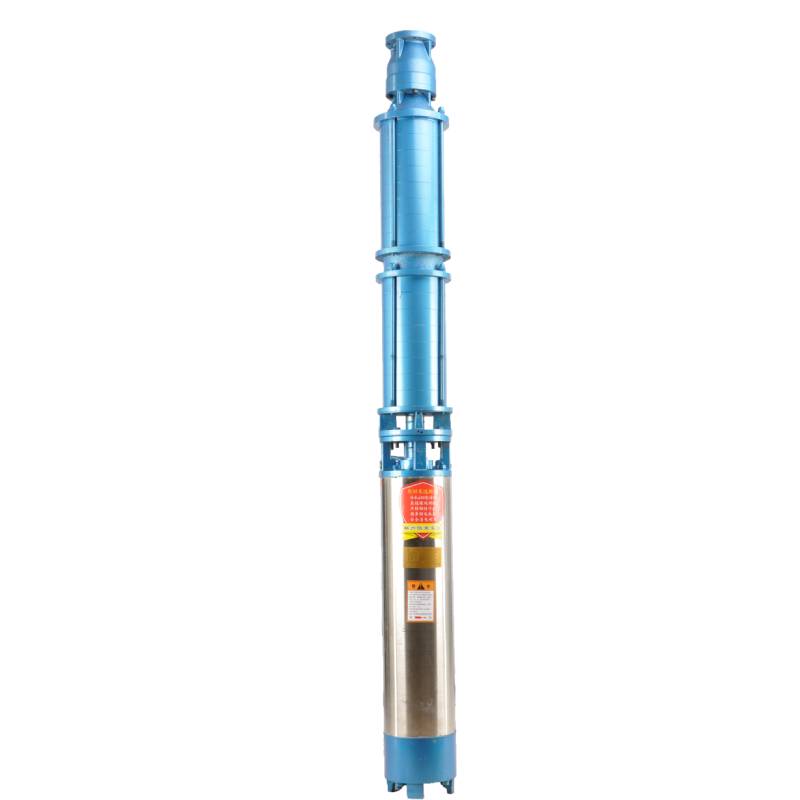
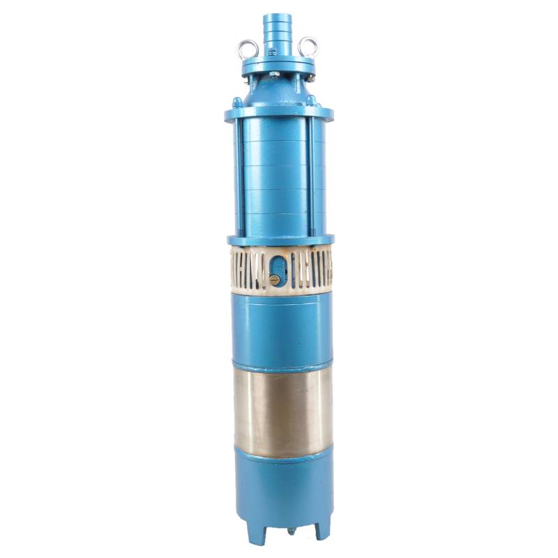
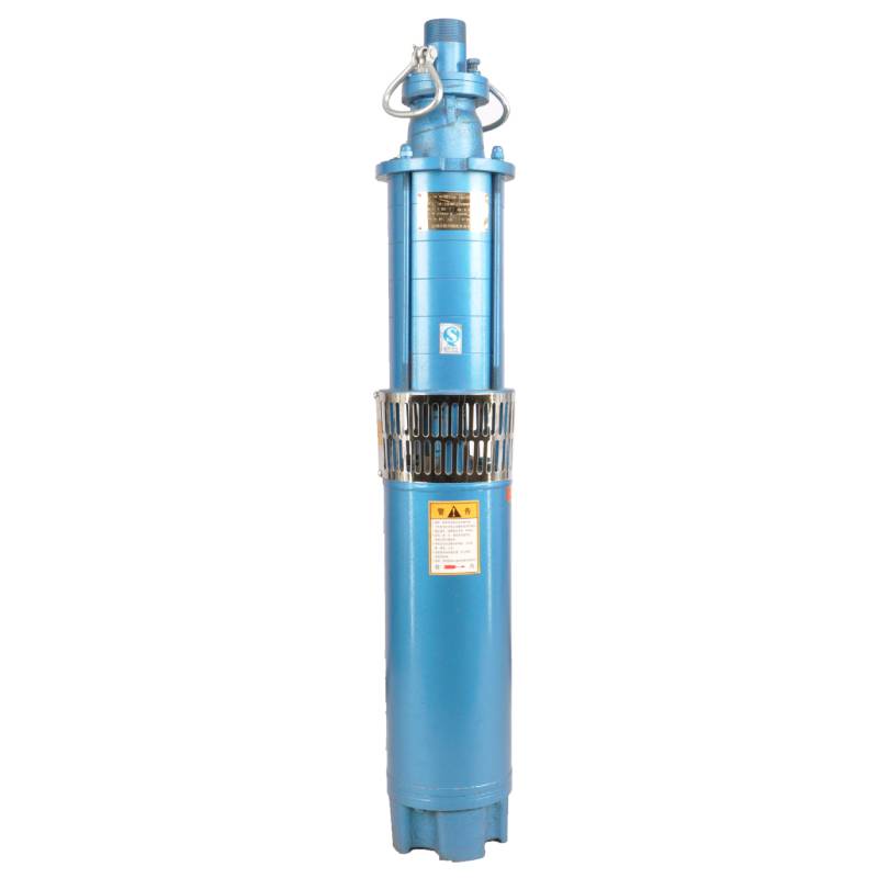
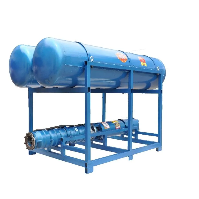
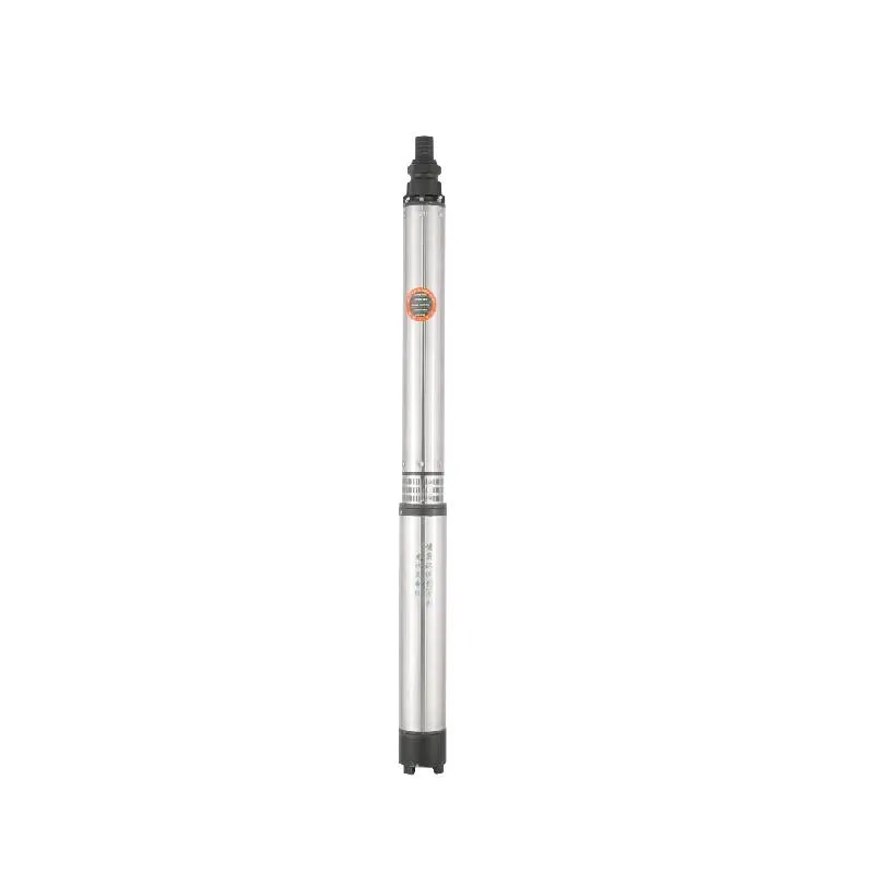
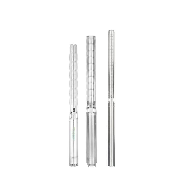
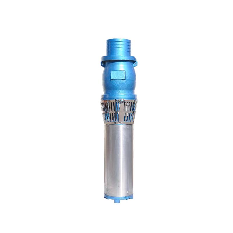
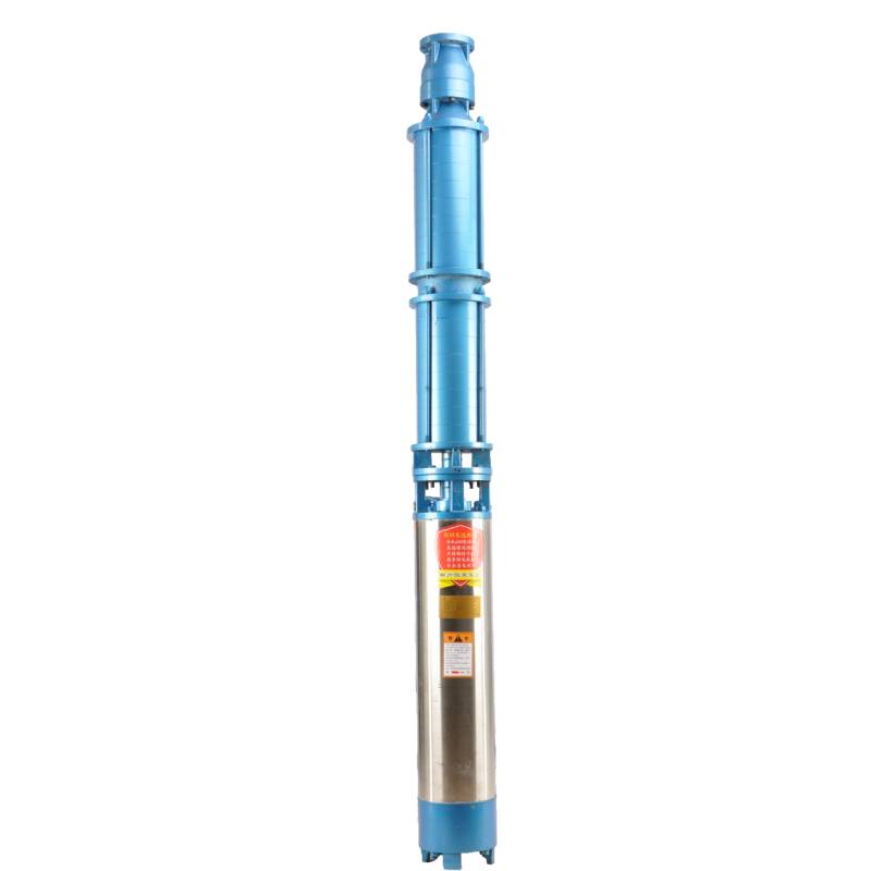
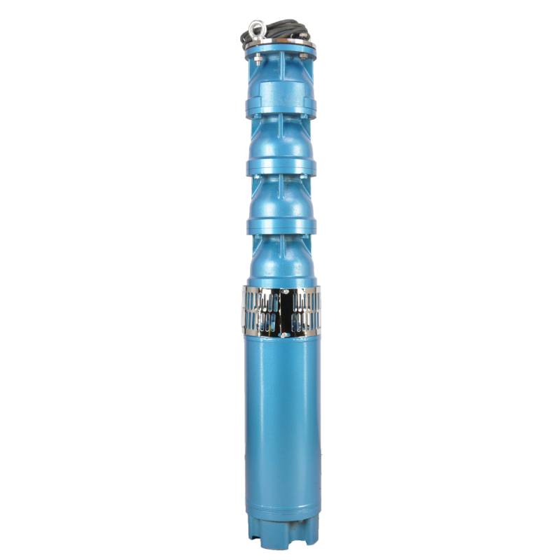
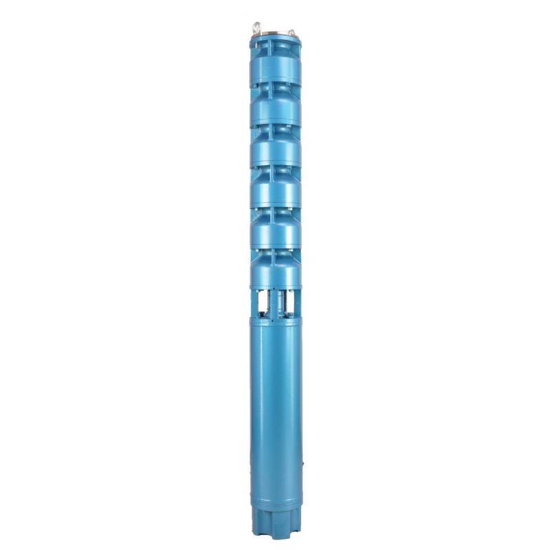
QS series submersible electric system is a new type of irrigation and drainage machinery. This series of pumps are vertical, using radial positive and negative guide vane design, small volume, light weight, high lift, easy installation and movement, easy maintenance and operation.
Flow range 5-50m3/h, lift 5-800m.
The product is equipped with three-phase AC 380V (tolerance is ± 5%), 50 Hz (tolerance is ± 1%) power supply. Water quality requirements are:
(1) water temperature shall not be higher than 20 °C;
(2) solid impurities content (mass ratio) shall not be greater than 0.01%;
(3) PH value (pH) is 6.5-8.5;
(4) hydrogen sulfide content shall not be greater than 1.5 mg / L;
(5) chloride ion content shall not be greater than 400 mg / L. The motor is a closed or water-filled wet structure.
Before use, the inner cavity of the submersible motor must be filled with clean water, and the water injection and air exhaust bolts shall be tightened, otherwise it shall not be used. The submersible pump must be completely immersed in water to work, the insertion depth shall not exceed 70 meters, and the distance between the bottom of the submersible pump and the bottom of the well shall not be less than 3 meters. The well water flow shall meet the water intake and continuous operation requirements of the submersible pump, and the water output of the submersible pump shall be controlled at 0.7-1.2 times the rated flow. The well must be vertical, and the submersible pump can not be used horizontally or inclined, but only vertically. The submersible pump must be matched with cables and equipped with external overload protection devices as required. The submersible pump is strictly prohibited from testing without water load.
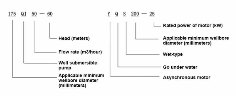
| 200 QS submersible pump performance table Non-standard customized series |
||||||||
| model | model | |||||||
| QS5-70-2.2KW | QS10-52-4KW | |||||||
| QS5-90-3KW | QS10-70-5.5KW | |||||||
| QS5-108-4KW | QS10-90-7.5KW | |||||||
| QS5-126-5.5KW | QS10-108-7.5KW | |||||||
| QS5-144-5.5KW | QS20-40-4KW | |||||||
| QS5-160-7.5KW | QS20-54-5.5KW | |||||||
| QS5-180-7.5KW | QS20-65-7.5KW | |||||||
| QS10-36-2.2KW | QS20-81-7.5KW | |||||||
| QS10-54-3KW | QS32-13-2.2KW | |||||||
| QS10-70-4KW | QS32-26-4KW | |||||||
| QS10-90-5.5KW | QS32-52-7.5KW | |||||||
| QS10-108-5.5KW | QS40-39-7.5KW | |||||||
| QS10-126-7.5KW | QS40-13-4KW | |||||||
| QS10-140-7.5KW | QS40-26-5.5KW | |||||||
| QS15-38-3KW | QS50-13-4KW | |||||||
| QS15-54-4KW | QS50-26-5.5KW | |||||||
| QS15-65-5.5KW | QS50-39-7.5KW | |||||||
| QS15-81-5.5KW | QS63-12-4KW | |||||||
| QS15-100-7.5KW | QS63-24-7.5KW | |||||||
| QS20-30-3KW | QS80-11-4KW | |||||||
| QS20-45-4KW | QS80-22-7.5KW | |||||||
| QS20-60-5.5KW | QS10-88-7.5KW | |||||||
| QS20-75-7.5KW | QS10-105-7.5KW | |||||||
| QS20-81-7.5KW | QS40-52-11KW | |||||||
| QS10-198-15KW | QS50-60-11KW | |||||||
| QS10-160-9.2KW | QS65-30-9.2KW | |||||||
| QS15-180-15KW | QS80-28-9.2KW | |||||||
| QS10-180-11KW | QS125-15-7.5KW | |||||||
1, well submersible pump for clean water pump, prohibit to wash new well, pumping sediment and muddy water,
2, well water pump voltage grade 380/50HZ, the use of other voltage grades of submersible motors need to be customized. Downhole cables must use waterproof cable, must be equipped with starting equipment, such as distribution box, start not ready should have common motor comprehensive protection function, such as short circuit overload protection, phase protection, undervoltage protection, grounding protection, idling protection, in case of abnormal conditions, the protection device should be timely action trip.
3, the pump must be reliably grounded in the process of installation and use. Prohibited in the hands and feet wet push-pull switch. Before installing and maintaining the pump, the power must be cut off. Installed in the place where the pump is used, it must be clearly marked "prevent electric shock". Before going down the well or installation, the motor cavity must be filled with distilled water or non-corrosive clean cold water, and fasten the water / drain bolt.
4, when the local interview operation of the pump, water must be poured into the pump chamber to lubricate the rubber bearing. The instant start time shall not exceed one second, check whether the direction is the same as the steering instruction. When the pump is upright, pay attention to safety, prevent overturning and injury.
5, strictly according to the provisions of the pump lift, flow range of use, to prevent low flow or high lift pumping force, the thrust bearing and other parts of the wear, the motor overload burned 6, after the pump down the well, the measurement of the motor to the ground insulation resistance should not be less than 100M, after the start to observe the voltage and current, check the motor winding insulation, whether in line with the requirements; pump storage location temperature if less than freezing point, should be dry the motor cavity water, prevent the motor cavity water ice damage caused by low temperature.
The pump part is mainly composed of pump shaft, impeller, guide housing, rubber bearing, check valve body (optional) and other components. The motor part mainly includes base, pressure regulating diaphragm, thrust bearing, thrust plate, lower guide bearing seat, stator, rotor, upper guide bearing seat, sand discharging ring, water inlet section, lead cable and other components. The main characteristics of this product are that the motor is a water-immersed three-phase asynchronous motor, and the motor cavity is filled with water to cool the motor and lubricate the bearing. The pressure regulating film at the bottom is used to adjust the pressure difference of the water body in the cavity caused by the temperature rise of the motor. In order to prevent the sand from entering the motor, the upper end of the motor shaft extension is equipped with two oil seals and installed a sand discharging ring, forming a sand prevention structure. At the same time, in order to prevent the pump shaft from jumping when starting, the pump shaft is connected with the motor shaft by a coupling, and the thrust bearing is installed under the motor. The lubrication of the whole product is water lubrication, and the motor stator winding is made of high quality submersible motor winding wire with high insulation performance. In addition, the pump is designed by computer CAD, with simple structure and excellent technical performance.

(1) Voorbereiding voor installasie:
1. Kontroleer of die dompelpomp voldoen aan die gebruiksvoorwaardes en omvang gespesifiseer in die handleiding.
2. Gebruik 'n swaar voorwerp met 'n deursnee gelyk aan die maksimum buitenste deursnee van die dompelpomp, meet of die binnedeursnee van die boorput by die dompelpomp kan pas, en meet of die putdiepte aan die installasievereistes voldoen.
3. Kontroleer of die boorput skoon is en of die putwater troebel is. Moet nooit 'n dompelpomp gebruik om die welor pomp modder en sand water te was om voortydige skade aan die dompel elektriese pomp te vermy.
4. Kontroleer of die posisie van die putkopinstallasieklem geskik is en of dit die kwaliteit van die hele eenheid kan weerstaan
5. Kontroleer of die dompelpompkomponente volledig en behoorlik geïnstalleer is volgens die samestellingsdiagram in die handleiding Verwyder die filterskerm en draai die koppeling om te sien of dit buigsaam draai
6. Skroef die waterskroef los en vul die motorholte met skoon, nie-korrosiewe water (let wel. maak seker dat jy dit vol maak), draai dan die waterskroef vas. Na 12 uur se waterinspuiting moet die isolasieweerstand van die motor nie minder as 150M Q wees as dit gemeet word met 'n 500V skudtafel nie.
7. Cable joint, cut off a 120mm rubber sleeve from one end of the outgoing cable and the matching cable with an electrician's knifethen stagger the length of the three core wires in a stepped shape, peel off a 20mm copper core, scrape of the oxide layer on theoutside of the copper wire with a knife or sand cloth, and insert the two connected wire ends in palirs.After tying the layer tightly with fine copper wire, solder it thoroughly and firmly, and sand of any. burrs on the surface. Then, forthe three joints, use polyvester insulation tape to wrap them in a semi stacked manner for three lavers. Wrap the two ends of thewrapping layer tightywith nyion thread,and then use a semi stacked method to wrap the tape for three layers. Wrap the outellayer with high-pressure insulation tape for three layers. Finally, fold the threestrands together and repeatedly wrap them for fivelayers with high-pressure tape. Each layer must be tightly tied, and the interlayer joints must be tight and fimm to prevent water frompenetrating and damaging the insulation, After wrapping, soak in water at room temperature of 20 ’c for 12 hours, and measurethe insulation resistance with a shaking table, which should not be less than 100M Ω
Die aangehegte kabelbedradingsprosesdiagram is soos volg: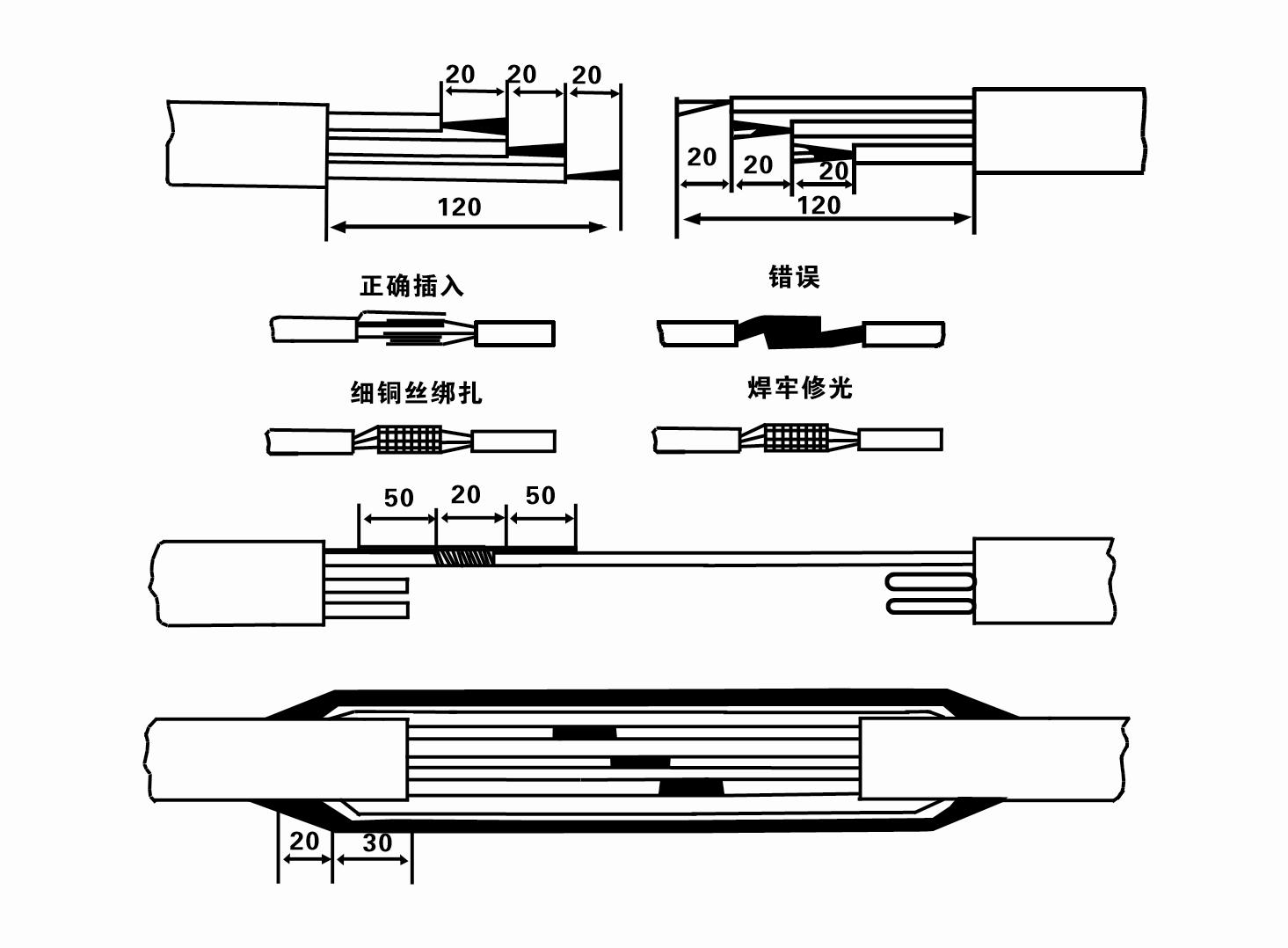
8. Gebruik 'n multimeter om te kyk of die driefase-drade verbind is en of die GS-weerstand ongeveer gebalanseerd is.
9. Kontroleer of die stroombaan en transformatorkapasiteit oorlaai is, en koppel dan die oorbelastingbeskermingskakelaar of aansittoerusting aan. Sien Tabel 2 vir spesifieke modelle, en Gooi dan 'n emmer water in die waterpomp vanaf die waterpompuitlaat om die rubberlaers in die pomp te smeer, en plaas dan die dompel elektriese pomp regop en bestendig.Begin (nie meer as een sekonde nie) en kyk of die stuurrigting ooreenstem met die stuurteken. Indien nie, ruil enige twee verbindings van die driefase-kabel om. Installeer dan die filter en maak gereed om in die put af te gaan. Indien dit in spesiale geleenthede gebruik word (soos slote, slote, riviere, damme, damme, ens.), moet die elektriese pomp betroubaar geaard wees.
(2) Installasie toerusting en gereedskap:
1. Een paar hyskettings vir meer as twee ton.
2. 'n Driepoot met 'n vertikale hoogte van nie minder nie as vier meter.
3. Twee hangtoue (draadtoue) wat 'n gewig van meer as een ton kan dra (kan die gewig van 'n volledige stel waterpompe dra).
4. Installeer twee pare klampe (spalke).
5. Sleutels, hamers, skroewedraaiers, elektriese gereedskap en instrumente, ens.
(3) Elektriese pompinstallasie:
1. Die installasiediagram van die dompel-elektriese pomp word in Figuur 2 getoon. Die spesifieke installasie-afmetings word in Tabel 3 "Lys van Installasie-afmetings van die dompel-elektriese pomp" getoon.
2. Dompelbare elektriese pompe met 'n hoogte van minder as 30 meter kan direk in die put gehys word deur gebruik te maak van slange en draadtoue of ander henneptoue wat die volle gewig van die hele masjien, waterpype en water in die pype kan dra.
3. Pompe met 'n hoogte van meer as 30 meter gebruik staalpype, en die installasievolgorde is soos volg:
①Gebruik 'n klem om die boonste punt van die waterpompdeel vas te klem (die motor en waterpomp is op hierdie tydstip gekoppel), lig dit met 'n hangketting en bind dit stadig in die put vas totdat Sit die klem op die putkop en verwyder die hang ketting.
② Gebruik nog 'n paar klampe om 'n pyp vas te klem, lig dit met 'n hangketting 15 cm weg van die flens af, en laat sak dit stadig. Tussen pypflens en pompflensSit die rubberkussing in plek en trek die pyp vas en pomp eweredig met boute, moere en veerringe.
③ Lig die dompelpomp effens op, verwyder die klem aan die boonste punt van die waterpomp, bind die kabel stewig aan die waterpyp vas met 'n plastiekband, en maak dit stadig vas totdat Die klem by die putkop geplaas is.
④Gebruik dieselfde metode om alle waterpype in die put vas te bind.
⑤ Nadat die uitloopkabel aan die beheerskakelaar gekoppel is, word dit aan die driefase-kragbron gekoppel.
(4) Dinge om op te let tydens installasie:
1. Indien 'n versteuringsverskynsel tydens die pompproses gevind word, draai of trek die waterpyp om die vassteekpunt te oorkom. As verskeie maatreëls steeds nie werk nie, moet asseblief nie die pomp af dwing om skade aan die dompelpomp en die put te voorkom nie.
2. Tydens installasie moet 'n rubberkussing by die flens van elke pyp geplaas word en eweredig vasgedraai word.
3. Wanneer die waterpomp in die put laat sak word, moet dit in die middel van die putpyp geplaas word om te verhoed dat die pomp vir 'n lang tyd teen die putwand loop, wat veroorsaak dat die pomp vibreer en die motor vee en brand .
4. Bepaal die diepte van die waterpomp tot by die bodem van die put volgens die vloeiende sand- en sliktoestande van die put. Moenie die pomp in die modder begrawe nie. Die afstand vanaf die waterpomp na die bodem van die put is oor die algemeen nie minder nie as 3 meter (sien Figuur 2).
5. Die watertoevoerdiepte van die waterpomp moet nie minder nie as 1-1,5 meter wees vanaf die dinamiese watervlak na die waterinlaatknooppunt (sien Figuur 2). Andersins kan die waterpomplaers maklik beskadig word.
6. Die hysbak van die waterpomp kan nie te laag wees nie. Andersins moet 'n hekklep op die putkopwaterpyplyn geïnstalleer word om die pompvloei by die aangewese vloeipunt te beheer om te verhoed dat die motor oorlaai en uitbrand as gevolg van groot vloeitempo's.
7. Wanneer die waterpomp aan die gang is, moet die wateruitset aaneenlopend en eweredig wees, die stroom moet stabiel wees (onder gegradeerde werksomstandighede, gewoonlik nie meer as 10% van die aangeslane stroom), en daar moet geen vibrasie of geraas wees nie. As daar enige abnormaliteit is, moet die masjien gestop word om die oorsaak uit te vind en dit uit te skakel.
8. Wanneer jy installeer, let op die instelling van die motor se aarddraad (sien Figuur 2). Wanneer die waterpyp 'n staalpyp is, lei dit uit die putkopklem; wanneer die waterpyp 'n plastiekpyp is, lei dit vanaf die aardmerk van die elektriese pomp.
The use of underwater pumps need to be carried out in strict accordance with the following steps: First of all, after the installation of the underwater pump, it is necessary to recheck the insulation resistance and the three-phase continuity of the switch, and check whether there are errors in the connection of the instrument and the start equipment. If there is no problem, you can start to test the machine. After the start, observe whether the indication readings of each instrument are correct. If the rated voltage and current specified on the nameplate are exceeded, please observe whether the pump has any noise or vibration. If everything is normal, it can be put into operation. The second step, after the pump runs for four hours for the first time, it should be closed and the thermal insulation resistance of the motor should be tested quickly. Its value should not be less than 0.5 megaohm. The third step, after the pump stops, it should be restarted after five minutes to prevent the water column in the pipeline from completely reversing, resulting in the motor burning due to excessive current. The fourth step, after the pump is put into normal operation, in order to prolong its service life, it is necessary to check the power supply voltage, operating current and insulation resistance regularly to see if they are normal. If the following conditions are found, the machine should be shut down immediately to troubleshoot:
1 the current exceeds 20% under the rated working conditions.
2 the dynamic water level drops to the inlet section, causing intermittent drainage.
3 the underwater pump vibrates violently or makes a lot of noise.
4 the supply voltage is lower than 340 volts.
5 a fuse burned. 6 water pipe damage.
7 the motor to the ground thermal insulation resistance is less than 0.5 megaohms.
The fifth step, the removal of the unit:
1 untie the cable tether, remove the pipe part, and remove the line protection plate.
2 screw down the water bolt and discharge all the water in the motor chamber.
3 remove the filter and loosen the fixing screw on the coupling fixed motor shaft.
4 screw down the bolt connecting the water inlet section and the motor, separate the pump and the motor (pay attention to make the unit level to prevent the bending of the pump shaft when separating)
5 the removal sequence of the pump is: (see Figure 1) water inlet section, impeller, shunt shell, impeller, check valve body. When removing the impeller, use special tools to loosen the cone sleeve fixed the impeller. In the process of removal, avoid bending the pump shaft and damage the various parts.
6 the removal process of the motor is: (see Figure 1) put the motor on the platform, and in order from the bottom of the motor bolt nuts, base, shaft head lock nut, thrust plate, key and lower guide bearing seat (iron rod bolt) on the connecting parts, and then take out the stator (careful not to damage the wire packet), and finally remove the connecting part and the upper guide bearing seat. Unit assembly: before assembly, rust and dirt on each component should be cleaned and sealant should be applied to each mating surface and fastener, and then the assembly should be carried out in reverse order of disassembly (the motor shaft moves about 1 mm after assembly), the coupling should be flexible after assembly, and then the filter should be put on for testing. Step six, after each use of the underwater electric pump operation for one year, or less than one year but immersed for two years, the disassembly and inspection should be carried out in accordance with the provisions of Article 5 to replace the worn parts.
1, sit die water in die motorholte uit (veral in die winter om te verhoed dat die motor vries), en bind die kabel goed vas.
2, store in an indoor room without corrosive substances and gases, with a temperature below 40 °C.
3, langtermyn gebruik moet aandag gee aan die roes voorkoming van dompelpompe.
- Impeller
- Skaghuls
- Rubber skag huls
-
Seëlring
01 Diep put water inname
02 Hoë watervoorsiening
03 bergwatervoorsiening
04 toring water
05 Landboubesproeiing
06 tuinbesproeiing
07 rivier water inname
08 huishoudelike water

