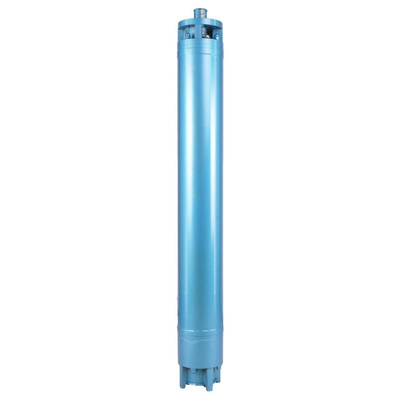
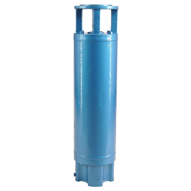
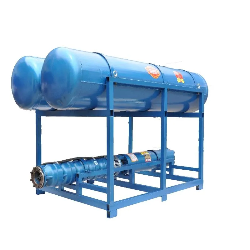
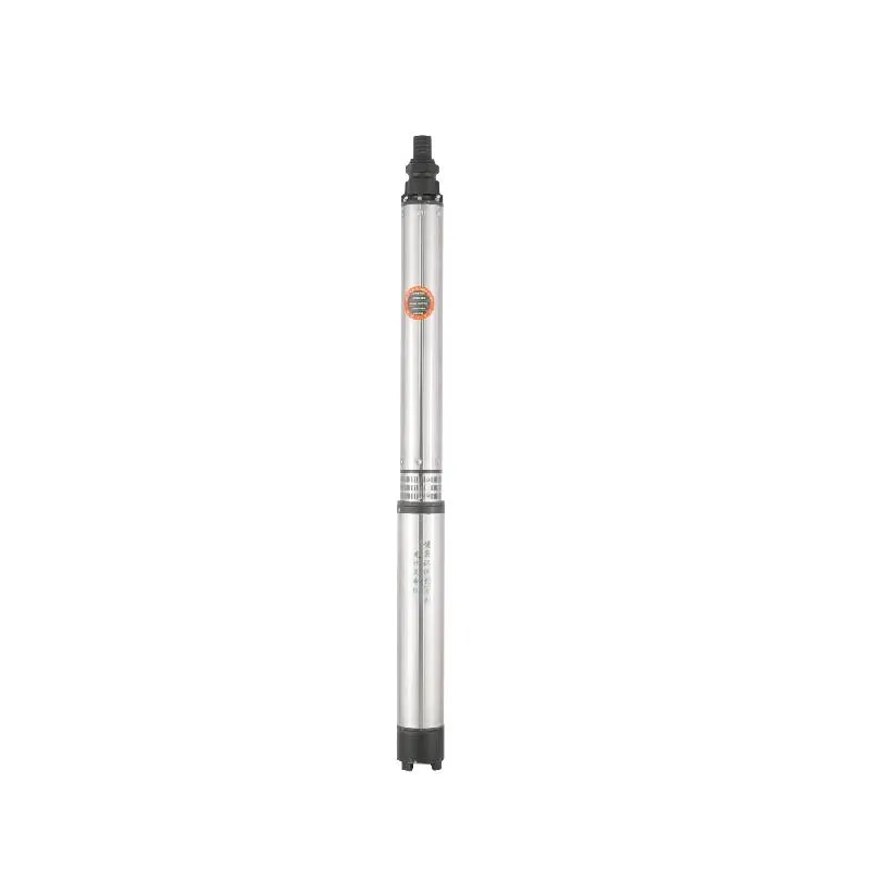
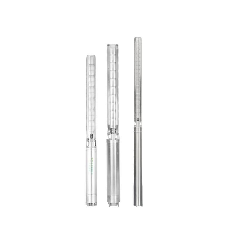
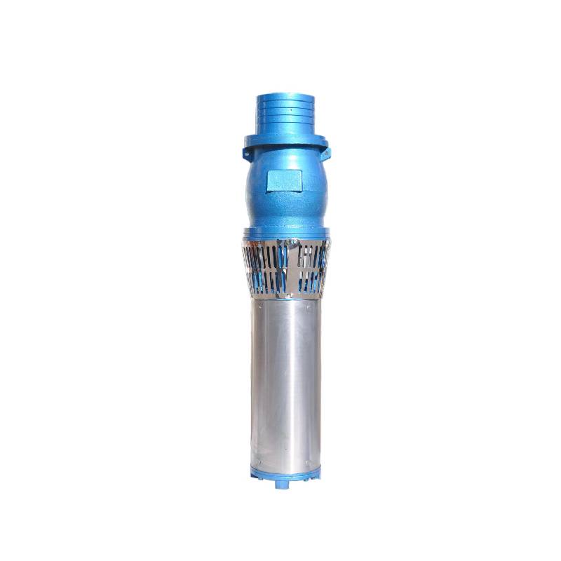
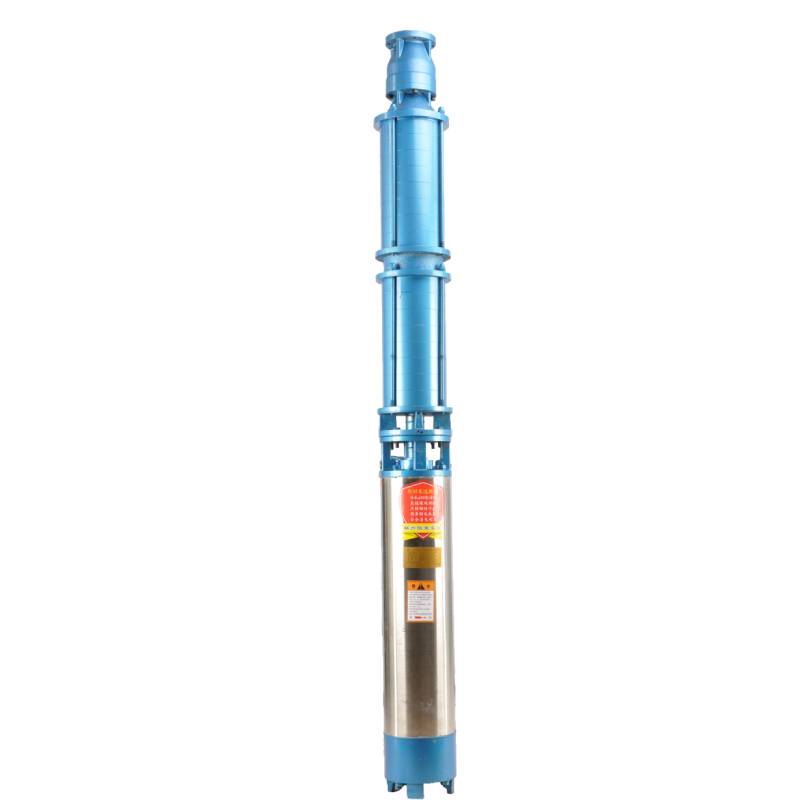
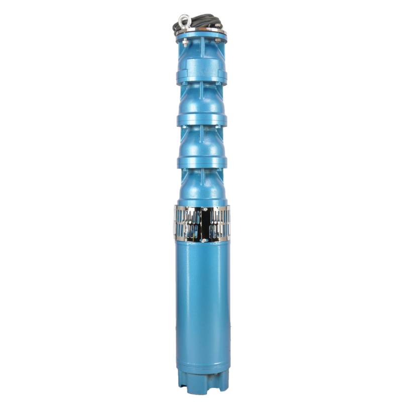
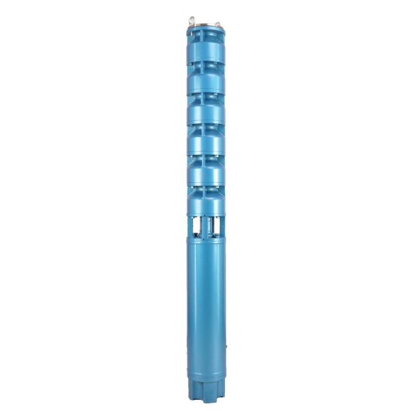
The product adopts special water-resistant wire for motor winding, with excellent characteristics such as high frequency shock resistance, pulse peak voltage shock resistance and high temperature aging resistance. The frequency conversion winding design ensures the motor to operate smoothly between 1Hz and 50Hz for a long time, making the frequency conversion deep well pump more energy saving and longer service life.
We are honored to introduce our products, this product provides three-phase AC 380V power supply (tolerance of ± 5%), 50HZ voltage (tolerance of ± 1%). At the same time, our products require strict water quality requirements: water temperature is not higher than 20 °C; solid impurities content (mass ratio) is not greater than 0.01%; PH value (pH) is 6.5-8.5; hydrogen sulfide content is not greater than 1.5mg/L; chloride ion content is not greater than 400mg/L. The motor adopts closed or water-filled wet structure, which must be filled with clean water before use to prevent empty. Tighten the water charging and deflating bolts before use, otherwise, it is not allowed to use. The submersible pump must be completely immersed in water to work, the immersion depth shall not exceed 70 meters, and the distance between the bottom of the submersible pump and the bottom of the well shall not be less than 3 meters. The well water flow shall meet the output and continuous operation requirements of the submersible pump, and the output of the submersible pump shall be controlled at 0.7-1.2 times of the rated flow. The well must be vertical, and the submersible pump can not be used horizontally or inverted, but only vertically. The submersible pump must be equipped with cables according to requirements, and is equipped with external overload protection devices. It is strictly prohibited to conduct no-load tests on the pump without water. Our products guarantee to provide you with high quality and stable performance, while meeting your needs to ensure safe and reliable.
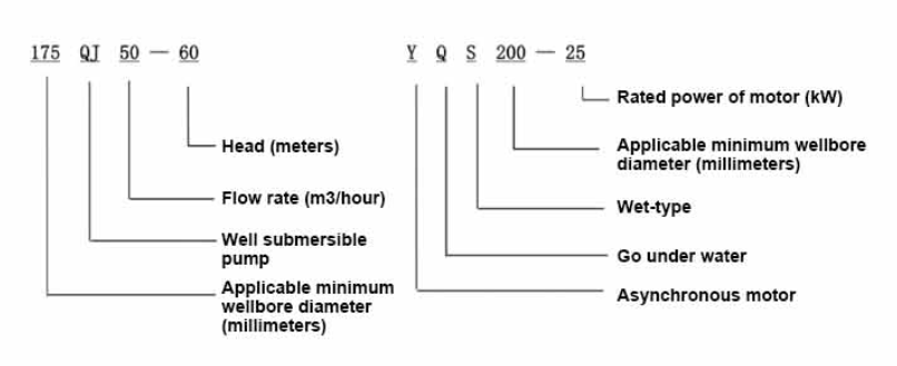
| Modello | Portata (m3/h) | Testa (M) |
Velocità di rotazione (cambiamento/punto) |
Pompa dell'acqua(%) | Presa diametro (mm) |
Applicabile bene diametro (millimetro) |
Valutato power(KW) |
Valutato tensione(V) |
Valutato corrente(A) |
Efficienza motoria (%) | power factorcosφ | Unità Dimensione massima radiale (mm) |
|||||||||
| 175QJ10-42 | 10 | 42 | 2850 | 53 | 50 | 175Sopra | 3 | 380 | 7.8 | 74.0 | 0.79 | 168 | |||||||||
| 175QJ10-56 | 56 | 4 | 10.1 | 76.0 | 0.79 | ||||||||||||||||
| 175QJ10-70 | 70 | 4 | 10.1 | 76.0 | 0.79 | ||||||||||||||||
| 175QJ10-84 | 84 | 5.5 | 13.6 | 77.0 | 0.8 | ||||||||||||||||
| 175QJ10-112 | 112 | 7.5 | 18.4 | 77.5 | 0.8 | ||||||||||||||||
| 175QJ10-126 | 126 | 7.5 | 18.4 | 77.5 | 0.8 | ||||||||||||||||
| 175QJ10-140 | 140 | 9.2 | 22.1 | 78.0 | 0.81 | ||||||||||||||||
| 175QJ15-42 | 15 | 42 | 2850 | 58 | 50 | 175Sopra | 4 | 380 | 10.1 | 76.0 | 0.79 | 168 | |||||||||
| 175QJ15-55 | 55 | 5.5 | 13.6 | 77.0 | 0.8 | ||||||||||||||||
| 175QJ15-65 | 65 | 5.5 | 13.6 | 77.0 | 0.8 | ||||||||||||||||
| 175QJ15-85 | 85 | 7.5 | 18.4 | 77.5 | 0.8 | ||||||||||||||||
| 175QJ15-112 | 112 | 9.2 | 22.1 | 78.0 | 0.81 | ||||||||||||||||
| 175QJ20-26 | 20 | 26 | 2850 | 64 | 50 | 175Sopra | 3 | 380 | 7.8 | 74.0 | 0.79 | 168 | |||||||||
| 175QJ20-39 | 39 | 4 | 10.1 | 76.0 | 0.79 | ||||||||||||||||
| 175QJ20-52 | 52 | 5.5 | 13.6 | 77.0 | 0.8 | ||||||||||||||||
| 175QJ20-78 | 78 | 7.5 | 18.4 | 77.5 | 0.8 | ||||||||||||||||
| 175QJ20-91 | 91 | 9.2 | 22.1 | 78.0 | 0.81 | ||||||||||||||||
| 175QJ20-104 | 104 | 11 | 26.1 | 79.0 | 0.81 | ||||||||||||||||
| 175QJ20-130 | 130 | 13 | 30.1 | 80.0 | 0.82 | ||||||||||||||||
| 175QJ20-156 | 156 | 15 | 34.7 | 80.0 | 0.82 | ||||||||||||||||
| 175QJ20-182 | 187 | 18.5 | 42.6 | 80.5 | 0.82 | ||||||||||||||||
| 175QJ20-208 | 208 | 22 | 49.7 | 81.0 | 0.83 | ||||||||||||||||
| 175QJ20-247 | 247 | 25 | 56.5 | 81.0 | 0.83 | ||||||||||||||||
| 175QJ20-273 | 273 | 30 | 66.6 | 81.5 | 0.84 | ||||||||||||||||
| 175QJ20-299 | 299 | 30 | 66.6 | 81.5 | 0.84 | ||||||||||||||||
| 175QJ20-325 | 325 | 32 | 71.0 | 81.5 | 0.84 | ||||||||||||||||
| 175QJ20-364 | 364 | 37 | 82.1 | 81.5 | 0.84 | ||||||||||||||||
| 175QJ25-26 | 25 | 26 | 2850 | 66 | 65 | 175Sopra | 3 | 380 | 7.8 | 74.0 | 0.79 | 168 | |||||||||
| 175QJ25-39 | 39 | 5.5 | 13.6 | 77.0 | 0.8 | ||||||||||||||||
| 175QJ25-65 | 25 | 65 | 2850 | 66 | 65 | 175Sopra | 7.5 | 380 | 18.4 | 77.5 | 0.8 | 168 | |||||||||
| 175QJ25-78 | 78 | 9.2 | 22.1 | 78.0 | 0.81 | ||||||||||||||||
| 175QJ25-91 | 91 | 11 | 26.1 | 79.0 | 0.81 | ||||||||||||||||
| 175QJ25-104 | 104 | 13 | 30.1 | 80.0 | 0.82 | ||||||||||||||||
| 175QJ25-130 | 130 | 15 | 34.7 | 80.0 | 0.82 | ||||||||||||||||
| 175QJ25-156 | 156 | 18.5 | 42.6 | 80.5 | 0.82 | ||||||||||||||||
| 175QJ25-182 | 182 | 22 | 49.7 | 81.0 | 0.83 | ||||||||||||||||
| 175QJ25-208 | 208 | 25 | 56.5 | 81.0 | 0.83 | ||||||||||||||||
| 175QJ25-221 | 221 | 30 | 66.6 | 81.5 | 0.84 | ||||||||||||||||
| 175QJ25-247 | 247 | 30 | 66.6 | 81.5 | 0.84 | ||||||||||||||||
| 175QJ25-260 | 260 | 32 | 71.0 | 81.5 | 0.84 | ||||||||||||||||
| 175QJ25-299 | 299 | 37 | 82.1 | 81.5 | 0.84 | ||||||||||||||||
| 175QJ30-30 | 30 | 30 | 2850 | 67 | 80 | 175Sopra | 4 | 380 | 10.1 | 76.0 | 0.79 | 168 | |||||||||
| 175QJ30-40 | 40 | 5.5 | 13.6 | 77.0 | 0.8 | ||||||||||||||||
| 175QJ32-24 | 32 | 24 | 2850 | 67 | 80 | 175Sopra | 4 | 380 | 10.1 | 76.0 | 0.79 | 168 | |||||||||
| 175QJ32-36 | 36 | 5.5 | 13.6 | 77.0 | 0.8 | ||||||||||||||||
| 175QJ32-48 | 48 | 7.5 | 18.4 | 77.5 | 0.8 | ||||||||||||||||
| 175QJ32-60 | 60 | 9.2 | 22.1 | 78.0 | 0.81 | ||||||||||||||||
| 175QJ32-72 | 72 | 11 | 26.1 | 79.0 | 0.81 | ||||||||||||||||
| 175QJ32-84 | 84 | 13 | 30.1 | 80.0 | 0.82 | ||||||||||||||||
| 175QJ32-96 | 96 | 15 | 34.7 | 80.0 | 0.82 | ||||||||||||||||
| 175QJ32-120 | 120 | 18.5 | 42.6 | 80.5 | 0.82 | ||||||||||||||||
| 175QJ32-144 | 144 | 22 | 49.7 | 81.0 | 0.83 | ||||||||||||||||
| 175QJ32-168 | 168 | 25 | 56.5 | 81.0 | 0.83 | ||||||||||||||||
| 175QJ32-180 | 180 | 30 | 66.6 | 81.5 | 0.84 | ||||||||||||||||
| 175QJ32-192 | 192 | 30 | 66.6 | 81.5 | 0.84 | ||||||||||||||||
| 175QJ32-204 | 204 | 32 | 71.0 | 81.5 | 0.84 | ||||||||||||||||
| 175QJ32-240 | 240 | 37 | 82.1 | 81.5 | 0.84 | ||||||||||||||||
| 175QJ35-60 | 35 | 60 | 2850 | 67 | 80 | 175Sopra | 10 | 380 | 25.0 | 78.0 | 0.78 | 168 | |||||||||
| 175QJ35-75 | 75 | 13 | 30.1 | 80.0 | 0.82 | ||||||||||||||||
| 175QJ35-100 | 100 | 17 | 40.9 | 80.0 | 0.79 | ||||||||||||||||
| 175QJ40-24 | 40 | 24 | 2850 | 70 | 80 | 175Sopra | 5.5 | 380 | 13.6 | 77.0 | 0.8 | 168 | |||||||||
| 175QJ40-30 | 30 | 5.5 | 13.6 | 77.0 | 0.8 | ||||||||||||||||
| 175QJ40-36 | 36 | 7.5 | 18.4 | 77.5 | 0.8 | ||||||||||||||||
| 175QJ40-48 | 48 | 9.2 | 22.1 | 78.0 | 0.81 | ||||||||||||||||
| 175QJ40-60 | 60 | 11 | 26.1 | 79.0 | 0.81 | ||||||||||||||||
| 175QJ40-72 | 72 | 13 | 30.1 | 80.0 | 0.82 | ||||||||||||||||
| 175QJ40-84 | 84 | 15 | 34.7 | 80.0 | 0.82 | ||||||||||||||||
| 175QJ40-96 | 96 | 18.5 | 42.6 | 80.5 | 0.82 | ||||||||||||||||
| 175QJ40-120 | 120 | 22 | 49.7 | 81.0 | 0.83 | ||||||||||||||||
| 175QJ40-132 | 132 | 25 | 56.5 | 81.0 | 0.83 | ||||||||||||||||
| 175QJ40-144 | 144 | 30 | 66.6 | 81.5 | 0.84 | ||||||||||||||||
| 175QJ40-156 | 156 | 30 | 66.6 | 81.5 | 0.84 | ||||||||||||||||
| 175QJ40-168 | 168 | 32 | 71.0 | 81.5 | 0.84 | ||||||||||||||||
| 175QJ40-192 | 192 | 37 | 82.1 | 81.5 | 0.84 | ||||||||||||||||
| 175QJ50-24 | 50 | 24 | 2850 | 72 | 80 | 175Sopra | 5.5 | 380 | 13.6 | 77.0 | 0.8 | 168 | |||||||||
| 175QJ50-36 | 36 | 9.2 | 22.1 | 78.0 | 0.81 | ||||||||||||||||
| 175QJ50-48 | 48 | 11 | 26.1 | 79.0 | 0.81 | ||||||||||||||||
| 175QJ50-60 | 60 | 13 | 30.1 | 80.0 | 0.82 | ||||||||||||||||
| 175QJ50-70 | 70 | 17 | 40.9 | 80.0 | 0.79 | ||||||||||||||||
| 175QJ50-84 | 84 | 18.5 | 42.6 | 80.5 | 0.82 | ||||||||||||||||
| 175QJ50-96 | 96 | 22 | 49.7 | 81.0 | 0.83 | ||||||||||||||||
| 175QJ50-108 | 108 | 25 | 56.5 | 81.0 | 0.83 | ||||||||||||||||
| 175QJ50-120 | 120 | 30 | 66.6 | 81.5 | 0.84 | ||||||||||||||||
| 175QJ50-132 | 132 | 30 | 66.6 | 81.5 | 0.84 | ||||||||||||||||
| 175QJ50-144 | 144 | 32 | 71.0 | 81.5 | 0.84 | ||||||||||||||||
| 175QJ50-156 | 156 | 37 | 82.1 | 81.5 | 0.84 | ||||||||||||||||
| 175QJ63-22 | 63 | 22 | 2850 | 72 | 80 | 175Sopra | 7.5 | 380 | 18.4 | 77.5 | 0.8 | 168 | |||||||||
| 175QJ63-44 | 44 | 13 | 30.1 | 80.0 | 0.82 | ||||||||||||||||
| 175QJ63-55 | 55 | 15 | 34.7 | 80.0 | 0.82 | ||||||||||||||||
| 175QJ63-66 | 66 | 18.5 | 42.6 | 80.5 | 0.82 | ||||||||||||||||
| 175QJ63-77 | 77 | 22 | 49.7 | 81.0 | 0.83 | ||||||||||||||||
| 175QJ63-88 | 88 | 25 | 56.5 | 81.0 | 0.83 | ||||||||||||||||
| 175QJ63-99 | 63 | 99 | 2850 | 72 | 80 | 175Sopra | 30 | 380 | 66.6 | 81.5 | 0.84 | 168 | |||||||||
| 175QJ63-110 | 110 | 32 | 71.0 | 81.5 | 0.84 | ||||||||||||||||
| 175QJ63-132 | 132 | 37 | 82.1 | 81.5 | 0.84 | ||||||||||||||||
| 175QJ80-9 | 80 | 9 | 2850 | 73 | 100 | 175Sopra | 4 | 380 | 10.1 | 76.0 | 0.79 | 168 | |||||||||
| 175QJ80-18 | 18 | 7.5 | 18.4 | 77.5 | 0.8 | ||||||||||||||||
| 175QJ80-27 | 27 | 11 | 26.1 | 79.0 | 0.81 | ||||||||||||||||
| 175QJ80-36 | 36 | 15 | 34.7 | 80.0 | 0.82 | ||||||||||||||||
| 175QJ80-45 | 45 | 18.5 | 42.6 | 80.5 | 0.82 | ||||||||||||||||
| 175QJ80-54 | 54 | 22 | 49.7 | 81.0 | 0.83 | ||||||||||||||||
| 175QJ80-63 | 63 | 25 | 56.5 | 81.0 | 0.83 | ||||||||||||||||
| 175QJ80-72 | 72 | 25 | 56.5 | 81.0 | 0.83 | ||||||||||||||||
| 175QJ80-81 | 81 | 30 | 66.6 | 81.5 | 0.84 | ||||||||||||||||
| 175QJ80-90 | 90 | 32 | 71.0 | 81.5 | 0.84 | ||||||||||||||||
| 175QJ80-98 | 98 | 37 | 82.1 | 81.5 | 0.84 | ||||||||||||||||
This well submersible pump is a pump suitable for clean water. Digging new wells and pumping sediment and turbid water are strictly prohibited. The voltage grade of the well pump is 380V/50HZ. Submersible motors with other voltage grades need to be customized. Underground cables must use waterproof cables and must be equipped with starting equipment, such as distribution boxes, etc. The starting equipment should have common comprehensive motor protection functions, such as overload short circuit protection, phase loss protection, undervoltage protection, grounding protection and idling protection, etc. In abnormal cases, the protection device should be tripped in time. During installation and use, the pump must be reliably grounded. It is prohibited to push and pull the switch when hands and feet are wet. The power supply must be cut off before installation and maintenance of the pump. The place where the pump is used must be set up with obvious "anti-electric shock" marks. Before going down the well or installation, the motor must be injected with distilled water or non-corrosive clear cold water in the inner cavity, and the intake/drain bolts must be tightened. When testing the pump on the ground, water must be injected into the pump chamber to lubricate the rubber bearings. The instant start time should not exceed one second to check whether the direction is correct. The same as the steering instructions. Pay attention to safety when the pump is upright to prevent tilting and injury. Strictly in accordance with the provisions of the pump lift and flow range, to prevent the pump flow at low lift or in high lift pull too large, resulting in extreme wear of thrust bearings and other components, the motor due to overload and burn. After put into the well, the measurement of the motor and the ground insulation resistance value, not less than 100M. After the start, regular observation of voltage and current, and check the motor winding insulation is in line with the requirements of the provisions. If the temperature of the storage site is below the freezing point, the water in the pump chamber should be drained to prevent the water in the motor chamber from freezing and damaging the motor due to low temperature.
Breve introduzione della struttura: la parte della pompa è composta principalmente da albero della pompa, girante, guscio di deviazione, cuscinetto in gomma, corpo della valvola di ritegno (parti opzionali) e altri componenti. La parte del motore è composta principalmente da base, pellicola di regolazione della pressione, cuscinetto reggispinta, piastra reggispinta, sede del cuscinetto guida inferiore, statore, rotore, sede del cuscinetto guida superiore, anello di sabbia, sezione di ingresso dell'acqua, cavo e altri componenti.
Le caratteristiche principali del prodotto includono:
1.The motor is a water-filled wet submersible three-phase asynchronous motor, the motor cavity is full of clean water, used to cool the motor and lubricate the bearing, the pressure regulating film at the bottom of the motor is used to adjust the expansion and contraction pressure difference of the water inside the body caused by the change of the temperature rise of the motor.
2.In order to prevent the sand in the well water from entering the motor, the upper end of the motor shaft is equipped with two oil seals, and a sand ring is installed to form a sand prevention structure.
3.In order to prevent the pump shaft from running up when starting, the pump shaft and the motor shaft are connected by a coupling, and an upper thrust bearing is installed at the lower part of the motor.
4.The lubrication of the motor and the pump bearing is water lubrication.
5.The motor stator winding is made of high quality submersible motor winding wire, with high insulation performance.
6.The pump is designed by computer CAD, with simple structure and good technical performance.

(1)Preparazione prima dell'installazione:
1. Controllare se la pompa sommersa soddisfa le condizioni di utilizzo e l'ambito specificato nel manuale.
2. Utilizzando un oggetto pesante con un diametro pari al diametro esterno massimo della pompa sommergibile, misurare se il diametro interno del pozzo può adattarsi alla pompa sommergibile e misurare se la profondità del pozzo soddisfa i requisiti di installazione.
3. Controllare se il pozzo è pulito e se l'acqua del pozzo è torbida. Non utilizzare mai un'elettropompa sommergibile per lavare la pompa welor dal fango e dall'acqua della sabbia per evitare danni prematuri all'elettropompa sommergibile.
4. Controllare se la posizione del morsetto di installazione della testa pozzo è adatta e se può sopportare la qualità dell'intera unità
5. Controllare se i componenti della pompa sommersa sono completi e installati correttamente secondo lo schema di montaggio nel manuale Rimuovere lo schermo del filtro e ruotare il giunto per vedere se ruota in modo flessibile
6. Svitare la vite dell'acqua e riempire la cavità del motore con acqua pulita e non corrosiva (nota: assicurarsi di riempirla), quindi serrare la vite dell'acqua. Dopo 12 ore di iniezione d'acqua, la resistenza di isolamento del motore non deve essere inferiore a 150 MQ se misurata con una tavola vibrante da 500 V.
7. Cable joint, cut off a 120mm rubber sleeve from one end of the outgoing cable and the matching cable with an electrician's knifethen stagger the length of the three core wires in a stepped shape, peel off a 20mm copper core, scrape of the oxide layer on theoutside of the copper wire with a knife or sand cloth, and insert the two connected wire ends in palirs.After tying the layer tightly with fine copper wire, solder it thoroughly and firmly, and sand of any. burrs on the surface. Then, forthe three joints, use polyvester insulation tape to wrap them in a semi stacked manner for three lavers. Wrap the two ends of thewrapping layer tightywith nyion thread,and then use a semi stacked method to wrap the tape for three layers. Wrap the outellayer with high-pressure insulation tape for three layers. Finally, fold the threestrands together and repeatedly wrap them for fivelayers with high-pressure tape. Each layer must be tightly tied, and the interlayer joints must be tight and fimm to prevent water frompenetrating and damaging the insulation, After wrapping, soak in water at room temperature of 20 ’c for 12 hours, and measurethe insulation resistance with a shaking table, which should not be less than 100M Ω
Lo schema del processo di cablaggio del cavo allegato è il seguente: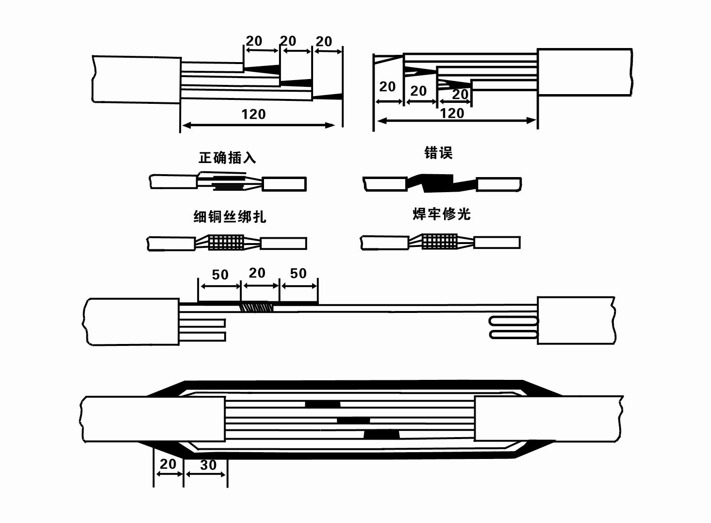
8. Utilizzare un multimetro per verificare se i cavi trifase sono collegati e se la resistenza CC è approssimativamente bilanciata.
9. Controllare se il circuito e la capacità del trasformatore sono sovraccarichi, quindi collegare l'interruttore di protezione da sovraccarico o l'apparecchiatura di avviamento. Vedere la Tabella 2 per i modelli specifici, quindi versare un secchio d'acqua nella pompa dell'acqua dall'uscita della pompa dell'acqua per lubrificare i cuscinetti di gomma nella pompa, quindi posizionare l'elettropompa sommergibile in posizione verticale e stabile. Avvio (non più di un secondo) e controllare se la direzione dello sterzo è coerente con il segnale dello sterzo. In caso contrario, scambia due connettori qualsiasi del cavo trifase. Quindi installa il filtro e preparati a scendere nel pozzo. Se utilizzata in occasioni particolari (come fossi, fossi, fiumi, stagni, stagni, ecc.), l'elettropompa deve essere collegata a terra in modo affidabile.
(2)Attrezzature e strumenti di installazione:
1. Una coppia di catene di sollevamento per più di due tonnellate.
2. Un treppiede con altezza verticale non inferiore a quattro metri.
3. Due funi sospese (funi metalliche) che possono sopportare un peso superiore a una tonnellata (possono sopportare il peso di un set completo di pompe dell'acqua).
4. Installare due paia di morsetti (stecche).
5. Chiavi inglesi, martelli, cacciaviti, utensili e strumenti elettrici, ecc.
(3)Installazione dell'elettropompa:
1. Lo schema di installazione dell'elettropompa sommergibile è mostrato nella Figura 2. Le dimensioni specifiche di installazione sono riportate nella Tabella 3 "Elenco dimensioni di installazione dell'elettropompa sommersa".
2. Le elettropompe sommergibili con una prevalenza inferiore a 30 metri possono essere issate direttamente nel pozzo utilizzando tubi flessibili e funi metalliche o altre funi di canapa in grado di sopportare l'intero peso dell'intera macchina, dei tubi dell'acqua e dell'acqua nei tubi.
3. Le pompe con una prevalenza superiore a 30 metri utilizzano tubi in acciaio e la sequenza di installazione è la seguente:
①Utilizzare un morsetto per bloccare l'estremità superiore della parte della pompa dell'acqua (il motore e la pompa dell'acqua sono stati collegati in questo momento), sollevarla con una catena sospesa e legarla lentamente nel pozzo finché non posizionare il morsetto sulla testa del pozzo e rimuovere il catena sospesa.
② Utilizzare un altro paio di fascette per serrare un tubo, sollevarlo con una catena sospesa a 15 cm di distanza dalla flangia e abbassarlo lentamente. Tra la flangia del tubo e la flangia della pompaMettere il cuscinetto in gomma in posizione e serrare il tubo e la pompa in modo uniforme con bulloni, dadi e rondelle elastiche.
③ Sollevare leggermente la pompa sommergibile, rimuovere il morsetto sull'estremità superiore della pompa dell'acqua, legare saldamente il cavo al tubo dell'acqua con un nastro di plastica e legarlo lentamente finché il morsetto non viene posizionato sulla testa del pozzo.
④Utilizzare lo stesso metodo per collegare tutti i tubi dell'acqua al pozzo.
⑤Dopo aver collegato il cavo di uscita all'interruttore di controllo, è collegato all'alimentazione trifase.
(4) Cose da notare durante l'installazione:
1. Se si riscontra un fenomeno di inceppamento durante il processo di pompaggio, girare o tirare il tubo dell'acqua per superare il punto di inceppamento. Se vari accorgimenti continuano a non funzionare, non forzare la pompa per evitare danni all'elettropompa sommergibile e al pozzo.
2. Durante l'installazione, posizionare un tampone di gomma sulla flangia di ciascun tubo e serrarlo uniformemente.
3. Quando la pompa dell'acqua viene abbassata nel pozzo, deve essere posizionata al centro del tubo del pozzo per evitare che la pompa funzioni a lungo contro la parete del pozzo, provocando vibrazioni della pompa e spazzamento e bruciatura del motore .
4. Determinare la profondità della pompa dell'acqua sul fondo del pozzo in base alle condizioni di scorrimento della sabbia e del limo nel pozzo. Non seppellire la pompa nel fango. La distanza dalla pompa dell'acqua al fondo del pozzo non è generalmente inferiore a 3 metri (vedi Figura 2).
5. La profondità di ingresso dell'acqua della pompa dell'acqua non deve essere inferiore a 1-1,5 metri dal livello dinamico dell'acqua al nodo di ingresso dell'acqua (vedere Figura 2). In caso contrario, i cuscinetti della pompa dell'acqua potrebbero danneggiarsi facilmente.
6. L'alzata della pompa dell'acqua non può essere troppo bassa. Altrimenti, è necessario installare una valvola a saracinesca sulla tubazione dell'acqua della testa del pozzo per controllare il flusso della pompa al punto di flusso nominale per evitare che il motore venga sovraccaricato e bruciato a causa delle grandi portate.
7. Quando la pompa dell'acqua è in funzione, l'uscita dell'acqua dovrebbe essere continua e uniforme, la corrente dovrebbe essere stabile (nelle condizioni di lavoro nominali, generalmente non più del 10% della corrente nominale) e non dovrebbero esserci vibrazioni o rumore. Se si riscontra qualche anomalia, è necessario arrestare la macchina per scoprirne la causa ed eliminarla.
8. Durante l'installazione, prestare attenzione all'impostazione del filo di terra del motore (vedere Figura 2). Quando la tubazione dell'acqua è di acciaio, farla uscire dal morsetto di testa pozzo; quando il tubo dell'acqua è di plastica, collegarlo al punto di messa a terra dell'elettropompa.
- 1.After installing the submersible pump, recheck the insulation resistance and three-phase continuity switch, check whether there is any error in the connection between the instrument and the starting equipment.If there is no problem, you can start to test the machine. After starting, observe whether the indication reading of each instrument is correct.If the rated voltage and current specified on the nameplate are exceeded, please observe whether the pump has noise or vibration.If everything is normal, it can be put into operation. After the pump runs for the first time for four hours, the motor thermal insulation resistance should be closed and tested quickly. Its value should not be less than 0.5 megaohm. After the pump stops, it should be restarted after five minutes to prevent the water column in the pipeline from completely reversing, which will cause the motor to burn out due to excessive current.
- 2.After the pump is put into normal operation, in order to prolong its service life, it is necessary to check whether the supply voltage, working current and insulation resistance are normal regularly. If the following conditions are found, the machine should be stopped immediately to troubleshoot.
- 1.Under the rated working condition, the current exceeds 20%.
- 2.The dynamic water level drops to the water inlet section, resulting in intermittent water.
- 3.The submersible pump has severe vibration or noise.
- 4.The supply voltage is lower than 340 volts.
- 5.A fuse is burned out.
- 6.The water pipeline is damaged.
- 7.The motor's insulation resistance to the geothermal state is lower than 0.5 megaohm.
- 3.Unit disassembly:
- - Slegare la fascetta, rimuovere la parte della tubazione e rimuovere la piastra metallica.
- - screw down the water bolt, put out the water in the motor chamber.
- - togliere il filtro, allentare la vite fissa sul giunto per fissare l'albero motore.
- 4.screw down the bolt connecting the water inlet section with the motor, and separate the pump from the motor (pay attention to the unit cushion when separating, to prevent the bending of the pump shaft)
- 5.the disassembly sequence of the pump is: (see figure 1) water inlet section, impeller, diversion shell, impeller...... check valve body, when removing the impeller, use special tools to loosen the conical sleeve of the fixed impeller first, and avoid bending and bruising the pump shaft in the process of disassembly.
- 6.the disassembly process of the motor is: (see figure 1) place the motor on the platform, and remove the nuts, base, shaft head locking nut, thrust plate, key, lower guide bearing seat and double head bolt from the bottom of the motor in turn, and then take out the rotor (pay attention not to damage the wire package) and finally remove the connecting section and upper guide bearing seat.
- 7.unit assembly: before assembly, the rust and dirt of the parts should be cleaned, and the mating surface and fasteners coated with sealant, and then assembled in the opposite order of disassembly (the motor shaft moves up and down after assembly for about one millimeter), after assembly, the coupling should be flexible, and then the filter screen test machine. Submersible pumps shall be taken out of the well for dismantling and maintenance according to Article 5 after a year of operation, or less than a year of operation but two years of diving time, and the worn parts shall be replaced.
1, far uscire l'acqua nella cavità del motore (soprattutto in inverno per evitare il congelamento del motore) e legare bene il cavo.
2, store in an indoor room without corrosive substances and gases, with a temperature below 40 °C.
3, l'uso a lungo termine dovrebbe prestare attenzione alla prevenzione della ruggine delle pompe sommergibili.
- Girante
- Manicotto dell'albero
- Manicotto dell'albero in gomma
-
Anello di tenuta
01 Presa d'acqua da pozzo profondo
02 Approvvigionamento idrico a molti piani
03 approvvigionamento idrico di montagna
04 torre d'acqua
05 Irrigazione agricola
06 irrigazione del giardino
07 presa d'acqua del fiume
08 acqua sanitaria


