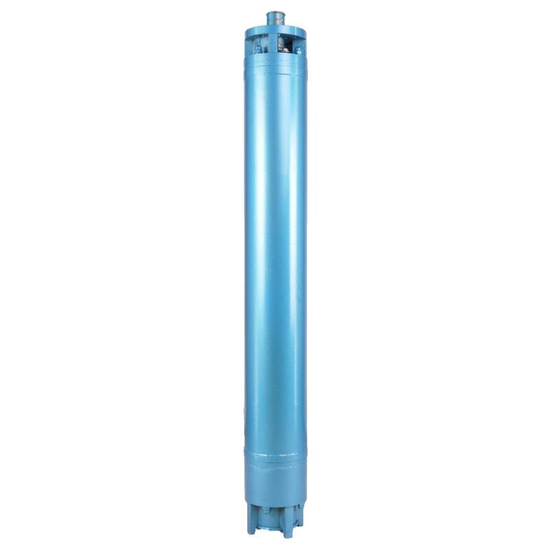
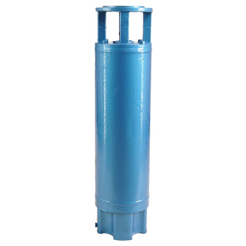
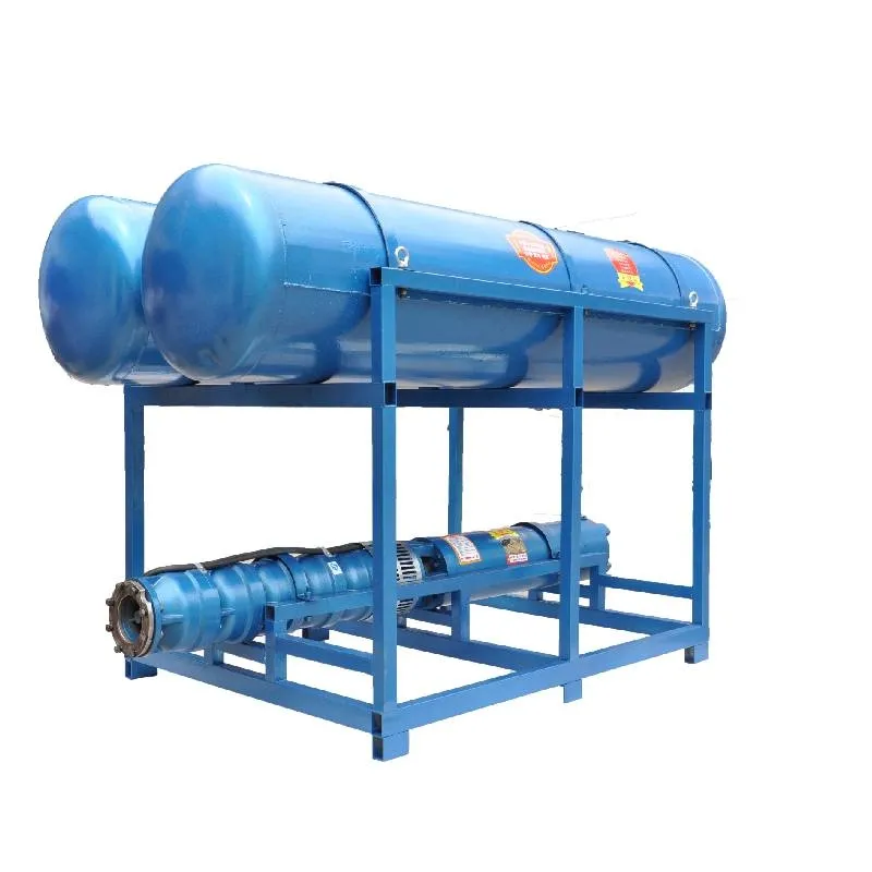
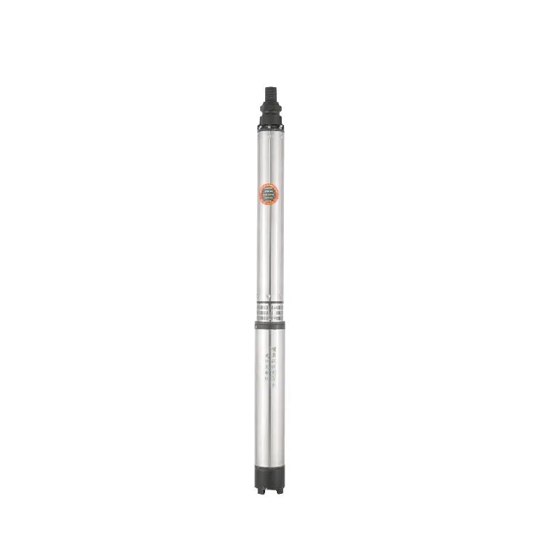
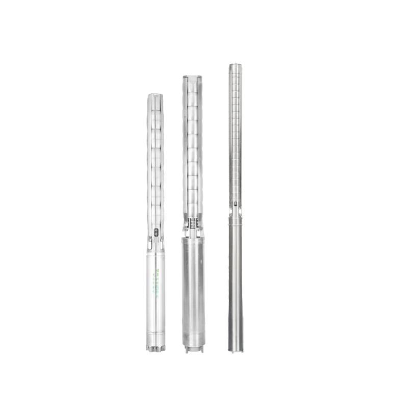
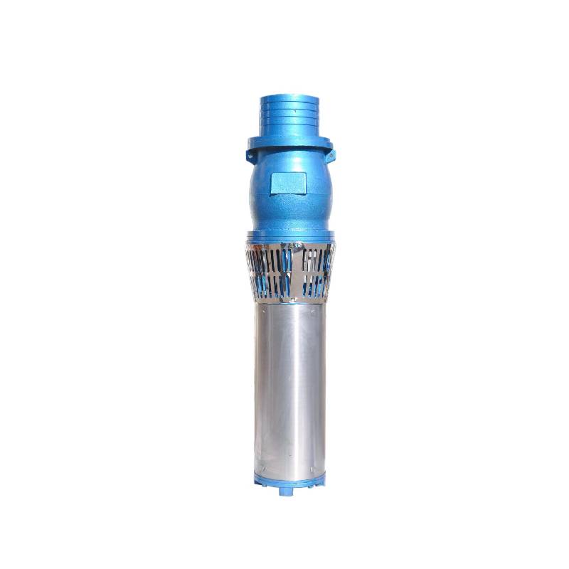
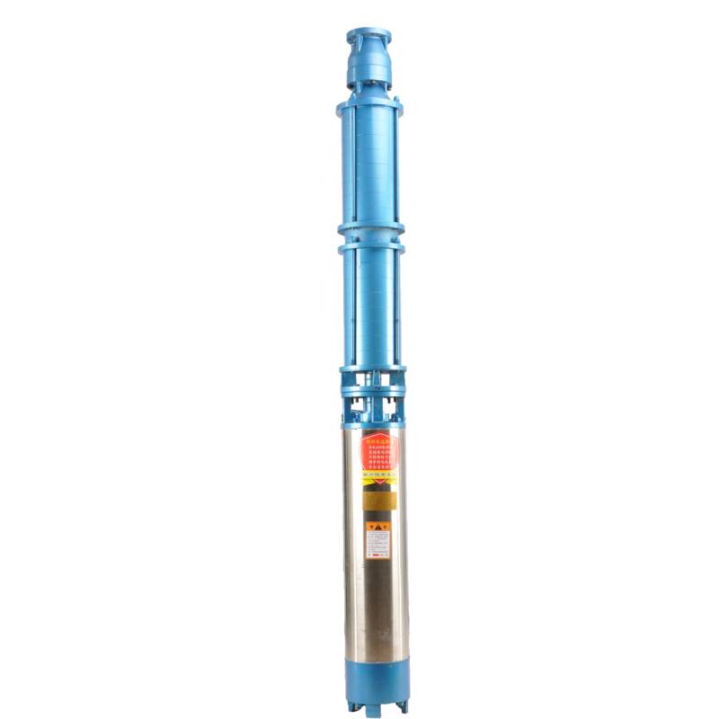
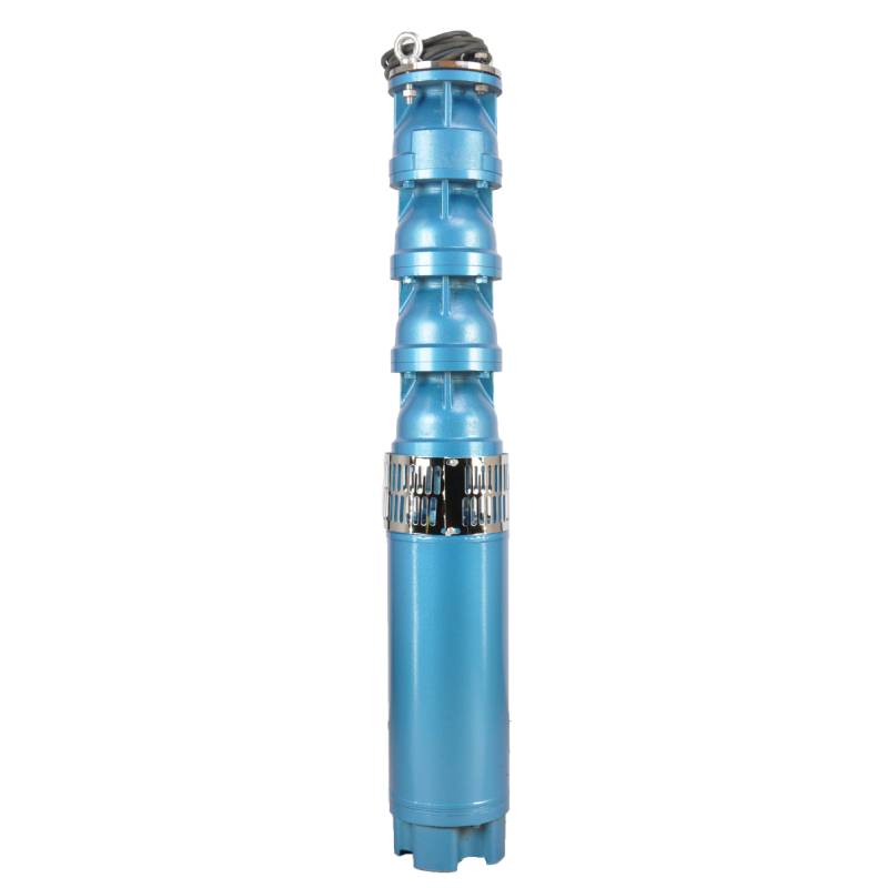
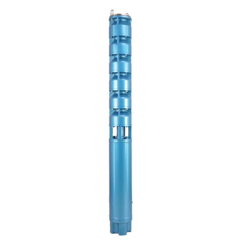
The product adopts special water-resistant wire for motor winding, with excellent characteristics such as high frequency shock resistance, pulse peak voltage shock resistance and high temperature aging resistance. The frequency conversion winding design ensures the motor to operate smoothly between 1Hz and 50Hz for a long time, making the frequency conversion deep well pump more energy saving and longer service life.
We are honored to introduce our products, this product provides three-phase AC 380V power supply (tolerance of ± 5%), 50HZ voltage (tolerance of ± 1%). At the same time, our products require strict water quality requirements: water temperature is not higher than 20 °C; solid impurities content (mass ratio) is not greater than 0.01%; PH value (pH) is 6.5-8.5; hydrogen sulfide content is not greater than 1.5mg/L; chloride ion content is not greater than 400mg/L. The motor adopts closed or water-filled wet structure, which must be filled with clean water before use to prevent empty. Tighten the water charging and deflating bolts before use, otherwise, it is not allowed to use. The submersible pump must be completely immersed in water to work, the immersion depth shall not exceed 70 meters, and the distance between the bottom of the submersible pump and the bottom of the well shall not be less than 3 meters. The well water flow shall meet the output and continuous operation requirements of the submersible pump, and the output of the submersible pump shall be controlled at 0.7-1.2 times of the rated flow. The well must be vertical, and the submersible pump can not be used horizontally or inverted, but only vertically. The submersible pump must be equipped with cables according to requirements, and is equipped with external overload protection devices. It is strictly prohibited to conduct no-load tests on the pump without water. Our products guarantee to provide you with high quality and stable performance, while meeting your needs to ensure safe and reliable.
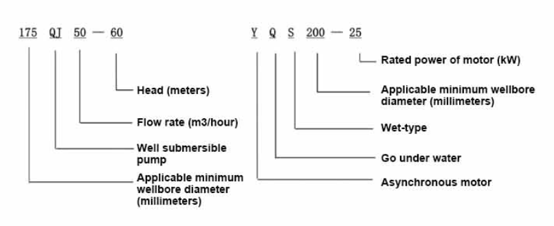
| Modelo | Caudal (m3/h) | Cabeza (metro) |
Velocidad de rotación (punto de cambio) |
Bomba de agua(%) | Salida diámetro (mm) |
Aplicable bien diámetro (mm) |
Clasificado power(KW) |
Clasificado voltaje(V) |
Clasificado corriente(A) |
Eficiencia motora (%) | power factorcosφ | Unidad Tamaño máximo radial (mm) |
|||||||||
| 175QJ10-42 | 10 | 42 | 2850 | 53 | 50 | 175arriba | 3 | 380 | 7.8 | 74.0 | 0.79 | 168 | |||||||||
| 175QJ10-56 | 56 | 4 | 10.1 | 76.0 | 0.79 | ||||||||||||||||
| 175QJ10-70 | 70 | 4 | 10.1 | 76.0 | 0.79 | ||||||||||||||||
| 175QJ10-84 | 84 | 5.5 | 13.6 | 77.0 | 0.8 | ||||||||||||||||
| 175QJ10-112 | 112 | 7.5 | 18.4 | 77.5 | 0.8 | ||||||||||||||||
| 175QJ10-126 | 126 | 7.5 | 18.4 | 77.5 | 0.8 | ||||||||||||||||
| 175QJ10-140 | 140 | 9.2 | 22.1 | 78.0 | 0.81 | ||||||||||||||||
| 175QJ15-42 | 15 | 42 | 2850 | 58 | 50 | 175arriba | 4 | 380 | 10.1 | 76.0 | 0.79 | 168 | |||||||||
| 175QJ15-55 | 55 | 5.5 | 13.6 | 77.0 | 0.8 | ||||||||||||||||
| 175QJ15-65 | 65 | 5.5 | 13.6 | 77.0 | 0.8 | ||||||||||||||||
| 175QJ15-85 | 85 | 7.5 | 18.4 | 77.5 | 0.8 | ||||||||||||||||
| 175QJ15-112 | 112 | 9.2 | 22.1 | 78.0 | 0.81 | ||||||||||||||||
| 175QJ20-26 | 20 | 26 | 2850 | 64 | 50 | 175arriba | 3 | 380 | 7.8 | 74.0 | 0.79 | 168 | |||||||||
| 175QJ20-39 | 39 | 4 | 10.1 | 76.0 | 0.79 | ||||||||||||||||
| 175QJ20-52 | 52 | 5.5 | 13.6 | 77.0 | 0.8 | ||||||||||||||||
| 175QJ20-78 | 78 | 7.5 | 18.4 | 77.5 | 0.8 | ||||||||||||||||
| 175QJ20-91 | 91 | 9.2 | 22.1 | 78.0 | 0.81 | ||||||||||||||||
| 175QJ20-104 | 104 | 11 | 26.1 | 79.0 | 0.81 | ||||||||||||||||
| 175QJ20-130 | 130 | 13 | 30.1 | 80.0 | 0.82 | ||||||||||||||||
| 175QJ20-156 | 156 | 15 | 34.7 | 80.0 | 0.82 | ||||||||||||||||
| 175QJ20-182 | 187 | 18.5 | 42.6 | 80.5 | 0.82 | ||||||||||||||||
| 175QJ20-208 | 208 | 22 | 49.7 | 81.0 | 0.83 | ||||||||||||||||
| 175QJ20-247 | 247 | 25 | 56.5 | 81.0 | 0.83 | ||||||||||||||||
| 175QJ20-273 | 273 | 30 | 66.6 | 81.5 | 0.84 | ||||||||||||||||
| 175QJ20-299 | 299 | 30 | 66.6 | 81.5 | 0.84 | ||||||||||||||||
| 175QJ20-325 | 325 | 32 | 71.0 | 81.5 | 0.84 | ||||||||||||||||
| 175QJ20-364 | 364 | 37 | 82.1 | 81.5 | 0.84 | ||||||||||||||||
| 175QJ25-26 | 25 | 26 | 2850 | 66 | 65 | 175arriba | 3 | 380 | 7.8 | 74.0 | 0.79 | 168 | |||||||||
| 175QJ25-39 | 39 | 5.5 | 13.6 | 77.0 | 0.8 | ||||||||||||||||
| 175QJ25-65 | 25 | 65 | 2850 | 66 | 65 | 175arriba | 7.5 | 380 | 18.4 | 77.5 | 0.8 | 168 | |||||||||
| 175QJ25-78 | 78 | 9.2 | 22.1 | 78.0 | 0.81 | ||||||||||||||||
| 175QJ25-91 | 91 | 11 | 26.1 | 79.0 | 0.81 | ||||||||||||||||
| 175QJ25-104 | 104 | 13 | 30.1 | 80.0 | 0.82 | ||||||||||||||||
| 175QJ25-130 | 130 | 15 | 34.7 | 80.0 | 0.82 | ||||||||||||||||
| 175QJ25-156 | 156 | 18.5 | 42.6 | 80.5 | 0.82 | ||||||||||||||||
| 175QJ25-182 | 182 | 22 | 49.7 | 81.0 | 0.83 | ||||||||||||||||
| 175QJ25-208 | 208 | 25 | 56.5 | 81.0 | 0.83 | ||||||||||||||||
| 175QJ25-221 | 221 | 30 | 66.6 | 81.5 | 0.84 | ||||||||||||||||
| 175QJ25-247 | 247 | 30 | 66.6 | 81.5 | 0.84 | ||||||||||||||||
| 175QJ25-260 | 260 | 32 | 71.0 | 81.5 | 0.84 | ||||||||||||||||
| 175QJ25-299 | 299 | 37 | 82.1 | 81.5 | 0.84 | ||||||||||||||||
| 175QJ30-30 | 30 | 30 | 2850 | 67 | 80 | 175arriba | 4 | 380 | 10.1 | 76.0 | 0.79 | 168 | |||||||||
| 175QJ30-40 | 40 | 5.5 | 13.6 | 77.0 | 0.8 | ||||||||||||||||
| 175QJ32-24 | 32 | 24 | 2850 | 67 | 80 | 175arriba | 4 | 380 | 10.1 | 76.0 | 0.79 | 168 | |||||||||
| 175QJ32-36 | 36 | 5.5 | 13.6 | 77.0 | 0.8 | ||||||||||||||||
| 175QJ32-48 | 48 | 7.5 | 18.4 | 77.5 | 0.8 | ||||||||||||||||
| 175QJ32-60 | 60 | 9.2 | 22.1 | 78.0 | 0.81 | ||||||||||||||||
| 175QJ32-72 | 72 | 11 | 26.1 | 79.0 | 0.81 | ||||||||||||||||
| 175QJ32-84 | 84 | 13 | 30.1 | 80.0 | 0.82 | ||||||||||||||||
| 175QJ32-96 | 96 | 15 | 34.7 | 80.0 | 0.82 | ||||||||||||||||
| 175QJ32-120 | 120 | 18.5 | 42.6 | 80.5 | 0.82 | ||||||||||||||||
| 175QJ32-144 | 144 | 22 | 49.7 | 81.0 | 0.83 | ||||||||||||||||
| 175QJ32-168 | 168 | 25 | 56.5 | 81.0 | 0.83 | ||||||||||||||||
| 175QJ32-180 | 180 | 30 | 66.6 | 81.5 | 0.84 | ||||||||||||||||
| 175QJ32-192 | 192 | 30 | 66.6 | 81.5 | 0.84 | ||||||||||||||||
| 175QJ32-204 | 204 | 32 | 71.0 | 81.5 | 0.84 | ||||||||||||||||
| 175QJ32-240 | 240 | 37 | 82.1 | 81.5 | 0.84 | ||||||||||||||||
| 175QJ35-60 | 35 | 60 | 2850 | 67 | 80 | 175arriba | 10 | 380 | 25.0 | 78.0 | 0.78 | 168 | |||||||||
| 175QJ35-75 | 75 | 13 | 30.1 | 80.0 | 0.82 | ||||||||||||||||
| 175QJ35-100 | 100 | 17 | 40.9 | 80.0 | 0.79 | ||||||||||||||||
| 175QJ40-24 | 40 | 24 | 2850 | 70 | 80 | 175arriba | 5.5 | 380 | 13.6 | 77.0 | 0.8 | 168 | |||||||||
| 175QJ40-30 | 30 | 5.5 | 13.6 | 77.0 | 0.8 | ||||||||||||||||
| 175QJ40-36 | 36 | 7.5 | 18.4 | 77.5 | 0.8 | ||||||||||||||||
| 175QJ40-48 | 48 | 9.2 | 22.1 | 78.0 | 0.81 | ||||||||||||||||
| 175QJ40-60 | 60 | 11 | 26.1 | 79.0 | 0.81 | ||||||||||||||||
| 175QJ40-72 | 72 | 13 | 30.1 | 80.0 | 0.82 | ||||||||||||||||
| 175QJ40-84 | 84 | 15 | 34.7 | 80.0 | 0.82 | ||||||||||||||||
| 175QJ40-96 | 96 | 18.5 | 42.6 | 80.5 | 0.82 | ||||||||||||||||
| 175QJ40-120 | 120 | 22 | 49.7 | 81.0 | 0.83 | ||||||||||||||||
| 175QJ40-132 | 132 | 25 | 56.5 | 81.0 | 0.83 | ||||||||||||||||
| 175QJ40-144 | 144 | 30 | 66.6 | 81.5 | 0.84 | ||||||||||||||||
| 175QJ40-156 | 156 | 30 | 66.6 | 81.5 | 0.84 | ||||||||||||||||
| 175QJ40-168 | 168 | 32 | 71.0 | 81.5 | 0.84 | ||||||||||||||||
| 175QJ40-192 | 192 | 37 | 82.1 | 81.5 | 0.84 | ||||||||||||||||
| 175QJ50-24 | 50 | 24 | 2850 | 72 | 80 | 175arriba | 5.5 | 380 | 13.6 | 77.0 | 0.8 | 168 | |||||||||
| 175QJ50-36 | 36 | 9.2 | 22.1 | 78.0 | 0.81 | ||||||||||||||||
| 175QJ50-48 | 48 | 11 | 26.1 | 79.0 | 0.81 | ||||||||||||||||
| 175QJ50-60 | 60 | 13 | 30.1 | 80.0 | 0.82 | ||||||||||||||||
| 175QJ50-70 | 70 | 17 | 40.9 | 80.0 | 0.79 | ||||||||||||||||
| 175QJ50-84 | 84 | 18.5 | 42.6 | 80.5 | 0.82 | ||||||||||||||||
| 175QJ50-96 | 96 | 22 | 49.7 | 81.0 | 0.83 | ||||||||||||||||
| 175QJ50-108 | 108 | 25 | 56.5 | 81.0 | 0.83 | ||||||||||||||||
| 175QJ50-120 | 120 | 30 | 66.6 | 81.5 | 0.84 | ||||||||||||||||
| 175QJ50-132 | 132 | 30 | 66.6 | 81.5 | 0.84 | ||||||||||||||||
| 175QJ50-144 | 144 | 32 | 71.0 | 81.5 | 0.84 | ||||||||||||||||
| 175QJ50-156 | 156 | 37 | 82.1 | 81.5 | 0.84 | ||||||||||||||||
| 175QJ63-22 | 63 | 22 | 2850 | 72 | 80 | 175arriba | 7.5 | 380 | 18.4 | 77.5 | 0.8 | 168 | |||||||||
| 175QJ63-44 | 44 | 13 | 30.1 | 80.0 | 0.82 | ||||||||||||||||
| 175QJ63-55 | 55 | 15 | 34.7 | 80.0 | 0.82 | ||||||||||||||||
| 175QJ63-66 | 66 | 18.5 | 42.6 | 80.5 | 0.82 | ||||||||||||||||
| 175QJ63-77 | 77 | 22 | 49.7 | 81.0 | 0.83 | ||||||||||||||||
| 175QJ63-88 | 88 | 25 | 56.5 | 81.0 | 0.83 | ||||||||||||||||
| 175QJ63-99 | 63 | 99 | 2850 | 72 | 80 | 175arriba | 30 | 380 | 66.6 | 81.5 | 0.84 | 168 | |||||||||
| 175QJ63-110 | 110 | 32 | 71.0 | 81.5 | 0.84 | ||||||||||||||||
| 175QJ63-132 | 132 | 37 | 82.1 | 81.5 | 0.84 | ||||||||||||||||
| 175QJ80-9 | 80 | 9 | 2850 | 73 | 100 | 175arriba | 4 | 380 | 10.1 | 76.0 | 0.79 | 168 | |||||||||
| 175QJ80-18 | 18 | 7.5 | 18.4 | 77.5 | 0.8 | ||||||||||||||||
| 175QJ80-27 | 27 | 11 | 26.1 | 79.0 | 0.81 | ||||||||||||||||
| 175QJ80-36 | 36 | 15 | 34.7 | 80.0 | 0.82 | ||||||||||||||||
| 175QJ80-45 | 45 | 18.5 | 42.6 | 80.5 | 0.82 | ||||||||||||||||
| 175QJ80-54 | 54 | 22 | 49.7 | 81.0 | 0.83 | ||||||||||||||||
| 175QJ80-63 | 63 | 25 | 56.5 | 81.0 | 0.83 | ||||||||||||||||
| 175QJ80-72 | 72 | 25 | 56.5 | 81.0 | 0.83 | ||||||||||||||||
| 175QJ80-81 | 81 | 30 | 66.6 | 81.5 | 0.84 | ||||||||||||||||
| 175QJ80-90 | 90 | 32 | 71.0 | 81.5 | 0.84 | ||||||||||||||||
| 175QJ80-98 | 98 | 37 | 82.1 | 81.5 | 0.84 | ||||||||||||||||
This well submersible pump is a pump suitable for clean water. Digging new wells and pumping sediment and turbid water are strictly prohibited. The voltage grade of the well pump is 380V/50HZ. Submersible motors with other voltage grades need to be customized. Underground cables must use waterproof cables and must be equipped with starting equipment, such as distribution boxes, etc. The starting equipment should have common comprehensive motor protection functions, such as overload short circuit protection, phase loss protection, undervoltage protection, grounding protection and idling protection, etc. In abnormal cases, the protection device should be tripped in time. During installation and use, the pump must be reliably grounded. It is prohibited to push and pull the switch when hands and feet are wet. The power supply must be cut off before installation and maintenance of the pump. The place where the pump is used must be set up with obvious "anti-electric shock" marks. Before going down the well or installation, the motor must be injected with distilled water or non-corrosive clear cold water in the inner cavity, and the intake/drain bolts must be tightened. When testing the pump on the ground, water must be injected into the pump chamber to lubricate the rubber bearings. The instant start time should not exceed one second to check whether the direction is correct. The same as the steering instructions. Pay attention to safety when the pump is upright to prevent tilting and injury. Strictly in accordance with the provisions of the pump lift and flow range, to prevent the pump flow at low lift or in high lift pull too large, resulting in extreme wear of thrust bearings and other components, the motor due to overload and burn. After put into the well, the measurement of the motor and the ground insulation resistance value, not less than 100M. After the start, regular observation of voltage and current, and check the motor winding insulation is in line with the requirements of the provisions. If the temperature of the storage site is below the freezing point, the water in the pump chamber should be drained to prevent the water in the motor chamber from freezing and damaging the motor due to low temperature.
Breve introducción de la estructura: la parte de la bomba se compone principalmente del eje de la bomba, el impulsor, la carcasa de desviación, el cojinete de goma, el cuerpo de la válvula de retención (piezas opcionales) y otros componentes. La parte del motor se compone principalmente de base, película reguladora de presión, cojinete de empuje, placa de empuje, asiento del cojinete guía inferior, estator, rotor, asiento del cojinete guía superior, anillo de arena, sección de entrada de agua, cable y otros componentes.
Las principales características del producto incluyen:
1.The motor is a water-filled wet submersible three-phase asynchronous motor, the motor cavity is full of clean water, used to cool the motor and lubricate the bearing, the pressure regulating film at the bottom of the motor is used to adjust the expansion and contraction pressure difference of the water inside the body caused by the change of the temperature rise of the motor.
2.In order to prevent the sand in the well water from entering the motor, the upper end of the motor shaft is equipped with two oil seals, and a sand ring is installed to form a sand prevention structure.
3.In order to prevent the pump shaft from running up when starting, the pump shaft and the motor shaft are connected by a coupling, and an upper thrust bearing is installed at the lower part of the motor.
4.The lubrication of the motor and the pump bearing is water lubrication.
5.The motor stator winding is made of high quality submersible motor winding wire, with high insulation performance.
6.The pump is designed by computer CAD, with simple structure and good technical performance.

(1)Preparación antes de la instalación:
1. Verifique si la bomba sumergible cumple con las condiciones de uso y el alcance especificado en el manual.
2. Utilizando un objeto pesado con un diámetro igual al diámetro exterior máximo de la bomba sumergible, mida si el diámetro interior del pozo puede adaptarse a la bomba sumergible y mida si la profundidad del pozo cumple con los requisitos de instalación.
3. Verifique si el pozo está limpio y si el agua del pozo está turbia. Nunca utilice una bomba eléctrica sumergible para lavar el agua de lodo y arena de la bomba welor para evitar daños prematuros a la bomba eléctrica sumergible.
4. Compruebe si la posición de la abrazadera de instalación del cabezal de pozo es adecuada y si puede soportar la calidad de toda la unidad.
5. Verifique si los componentes de la bomba sumergible están completos e instalados correctamente de acuerdo con el diagrama de ensamblaje en el manual. Retire la pantalla del filtro y gire el acoplamiento para ver si gira con flexibilidad.
6. Desenrosque el tornillo de agua y llene la cavidad del motor con agua limpia y no corrosiva (nota: asegúrese de llenarla), luego apriete el tornillo de agua. Después de 12 horas de inyección de agua, la resistencia de aislamiento del motor no debe ser inferior a 150 M Q cuando se mide con una mesa vibratoria de 500 V.
7. Cable joint, cut off a 120mm rubber sleeve from one end of the outgoing cable and the matching cable with an electrician's knifethen stagger the length of the three core wires in a stepped shape, peel off a 20mm copper core, scrape of the oxide layer on theoutside of the copper wire with a knife or sand cloth, and insert the two connected wire ends in palirs.After tying the layer tightly with fine copper wire, solder it thoroughly and firmly, and sand of any. burrs on the surface. Then, forthe three joints, use polyvester insulation tape to wrap them in a semi stacked manner for three lavers. Wrap the two ends of thewrapping layer tightywith nyion thread,and then use a semi stacked method to wrap the tape for three layers. Wrap the outellayer with high-pressure insulation tape for three layers. Finally, fold the threestrands together and repeatedly wrap them for fivelayers with high-pressure tape. Each layer must be tightly tied, and the interlayer joints must be tight and fimm to prevent water frompenetrating and damaging the insulation, After wrapping, soak in water at room temperature of 20 ’c for 12 hours, and measurethe insulation resistance with a shaking table, which should not be less than 100M Ω
El diagrama del proceso de cableado del cable adjunto es el siguiente: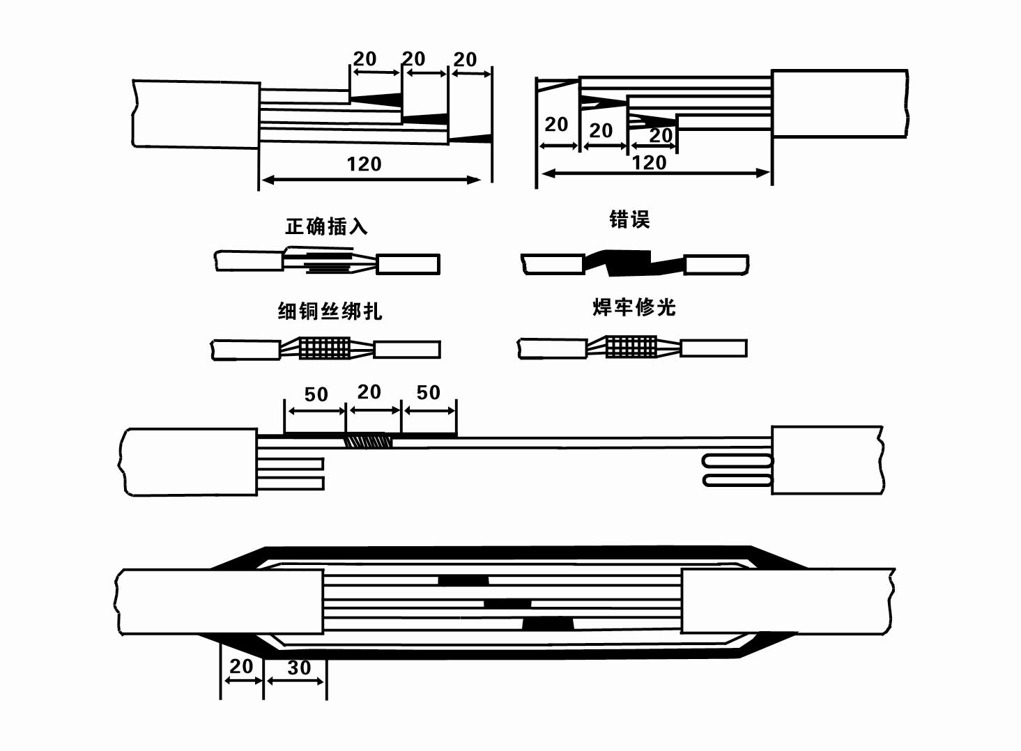
8. Utilice un multímetro para comprobar si los cables trifásicos están conectados y si la resistencia de CC está aproximadamente equilibrada.
9. Verifique si el circuito y la capacidad del transformador están sobrecargados y luego conecte el interruptor de protección contra sobrecarga o el equipo de arranque. Consulte la Tabla 2 para conocer modelos específicos y luego vierta un balde de agua en la bomba de agua desde la salida de la bomba de agua para lubricar los cojinetes de goma de la bomba y luego coloque la bomba eléctrica sumergible en posición vertical y estable. Inicio (no más de un segundo) y compruebe si la dirección de dirección es consistente con la señal de dirección. De lo contrario, cambie los dos conectores del cable trifásico. Luego instale el filtro y prepárese para bajar al pozo. Si se utiliza en ocasiones especiales (como zanjas, acequias, ríos, estanques, estanques, etc.), la bomba eléctrica debe estar conectada a tierra de manera confiable.
(2) Equipos y herramientas de instalación:
1. Un par de cadenas de elevación para más de dos toneladas.
2. Un trípode con una altura vertical no inferior a cuatro metros.
3. Dos cuerdas para colgar (cables de alambre) que pueden soportar un peso de más de una tonelada (pueden soportar el peso de un juego completo de bombas de agua).
4. Instale dos pares de abrazaderas (férulas).
5. Llaves, martillos, destornilladores, herramientas e instrumentos eléctricos, etc.
(3)Instalación de bomba eléctrica:
1. El diagrama de instalación de la bomba eléctrica sumergible se muestra en la Figura 2. Las dimensiones de instalación específicas se muestran en la Tabla 3 "Lista de dimensiones de instalación de la bomba eléctrica sumergible".
2. Las bombas eléctricas sumergibles con una altura inferior a 30 metros se pueden izar directamente al pozo utilizando mangueras y cables metálicos u otros cables de cáñamo que puedan soportar todo el peso de toda la máquina, las tuberías de agua y el agua en las tuberías.
3. Las bombas con una altura de más de 30 metros utilizan tuberías de acero y la secuencia de instalación es la siguiente:
①Utilice una abrazadera para sujetar el extremo superior de la parte de la bomba de agua (el motor y la bomba de agua se han conectado en este momento), levántelo con una cadena colgante y átelo lentamente al pozo hasta que coloque la abrazadera en la boca del pozo y retire la cadena colgante.
② Utilice otro par de abrazaderas para sujetar un tubo, levántelo con una cadena colgante a 15 cm de la brida y bájelo lentamente. Entre la brida de la tubería y la brida de la bomba Coloque la almohadilla de goma en su lugar y apriete la tubería y la bomba de manera uniforme con pernos, tuercas y arandelas de resorte.
③ Levante ligeramente la bomba sumergible, retire la abrazadera en el extremo superior de la bomba de agua, ate el cable firmemente a la tubería de agua con una cinta plástica y átelo lentamente hasta que la abrazadera quede colocada en la boca del pozo.
④Utilice el mismo método para conectar todas las tuberías de agua al pozo.
⑤Después de conectar el cable de salida al interruptor de control, se conecta a la fuente de alimentación trifásica.
(4) Cosas a tener en cuenta durante la instalación:
1. Si se encuentra un fenómeno de atasco durante el proceso de bombeo, gire o tire de la tubería de agua para superar el punto de atasco. Si varias medidas aún no funcionan, no fuerce la bomba hacia abajo para evitar daños a la bomba eléctrica sumergible y al pozo.
2. Durante la instalación, se debe colocar una almohadilla de goma en la brida de cada tubería y apretarla uniformemente.
3. Cuando la bomba de agua se baja al pozo, debe colocarse en el medio de la tubería del pozo para evitar que la bomba funcione contra la pared del pozo durante mucho tiempo, lo que hace que la bomba vibre y el motor barre y quema. .
4. Determine la profundidad de la bomba de agua hasta el fondo del pozo de acuerdo con las condiciones del flujo de arena y limo del pozo. No entierre la bomba en el barro. La distancia desde la bomba de agua hasta el fondo del pozo generalmente no es inferior a 3 metros (ver Figura 2).
5. La profundidad de entrada de agua de la bomba de agua no debe ser inferior a 1-1,5 metros desde el nivel dinámico del agua hasta el nodo de entrada de agua (consulte la Figura 2). De lo contrario, los cojinetes de la bomba de agua podrían dañarse fácilmente.
6. La elevación de la bomba de agua no puede ser demasiado baja. De lo contrario, se debe instalar una válvula de compuerta en la tubería de agua de la boca del pozo para controlar el flujo de la bomba en el punto de flujo nominal y evitar que el motor se sobrecargue y se queme debido a grandes caudales.
7. Cuando la bomba de agua está funcionando, la salida de agua debe ser continua y uniforme, la corriente debe ser estable (en condiciones de trabajo nominales, generalmente no más del 10% de la corriente nominal) y no debe haber vibraciones ni ruidos. Si hay alguna anomalía, se debe detener la máquina para descubrir la causa y eliminarla.
8. Al realizar la instalación, preste atención a la configuración del cable de tierra del motor (consulte la Figura 2). Cuando la tubería de agua sea de acero, condúzcala desde la abrazadera del cabezal del pozo; Cuando la tubería de agua sea de plástico, condúzcala desde la marca de conexión a tierra de la bomba eléctrica.
- 1.After installing the submersible pump, recheck the insulation resistance and three-phase continuity switch, check whether there is any error in the connection between the instrument and the starting equipment.If there is no problem, you can start to test the machine. After starting, observe whether the indication reading of each instrument is correct.If the rated voltage and current specified on the nameplate are exceeded, please observe whether the pump has noise or vibration.If everything is normal, it can be put into operation. After the pump runs for the first time for four hours, the motor thermal insulation resistance should be closed and tested quickly. Its value should not be less than 0.5 megaohm. After the pump stops, it should be restarted after five minutes to prevent the water column in the pipeline from completely reversing, which will cause the motor to burn out due to excessive current.
- 2.After the pump is put into normal operation, in order to prolong its service life, it is necessary to check whether the supply voltage, working current and insulation resistance are normal regularly. If the following conditions are found, the machine should be stopped immediately to troubleshoot.
- 1.Under the rated working condition, the current exceeds 20%.
- 2.The dynamic water level drops to the water inlet section, resulting in intermittent water.
- 3.The submersible pump has severe vibration or noise.
- 4.The supply voltage is lower than 340 volts.
- 5.A fuse is burned out.
- 6.The water pipeline is damaged.
- 7.The motor's insulation resistance to the geothermal state is lower than 0.5 megaohm.
- 3.Unit disassembly:
- - Desatar la brida para cables, quitar la parte de la tubería y quitar la placa de alambre.
- - screw down the water bolt, put out the water in the motor chamber.
- - quitar el filtro, aflojar el tornillo fijado en el acoplamiento para fijar el eje del motor.
- 4.screw down the bolt connecting the water inlet section with the motor, and separate the pump from the motor (pay attention to the unit cushion when separating, to prevent the bending of the pump shaft)
- 5.the disassembly sequence of the pump is: (see figure 1) water inlet section, impeller, diversion shell, impeller...... check valve body, when removing the impeller, use special tools to loosen the conical sleeve of the fixed impeller first, and avoid bending and bruising the pump shaft in the process of disassembly.
- 6.the disassembly process of the motor is: (see figure 1) place the motor on the platform, and remove the nuts, base, shaft head locking nut, thrust plate, key, lower guide bearing seat and double head bolt from the bottom of the motor in turn, and then take out the rotor (pay attention not to damage the wire package) and finally remove the connecting section and upper guide bearing seat.
- 7.unit assembly: before assembly, the rust and dirt of the parts should be cleaned, and the mating surface and fasteners coated with sealant, and then assembled in the opposite order of disassembly (the motor shaft moves up and down after assembly for about one millimeter), after assembly, the coupling should be flexible, and then the filter screen test machine. Submersible pumps shall be taken out of the well for dismantling and maintenance according to Article 5 after a year of operation, or less than a year of operation but two years of diving time, and the worn parts shall be replaced.
1, saque el agua de la cavidad del motor (especialmente en invierno para evitar que el motor se congele) y ate bien el cable.
2, store in an indoor room without corrosive substances and gases, with a temperature below 40 °C.
3. El uso prolongado debe prestar atención a la prevención de la oxidación de las bombas sumergibles.
- Impulso
- Camisa del eje
- Manguito de eje de goma
-
anillo de sellado
01 Toma de agua de pozo profundo
02 Suministro de agua en altura
03 suministro de agua de montaña
04 torre de agua
05 Riego agrícola
06 riego de jardines
07 toma de agua del río
08 agua sanitaria


