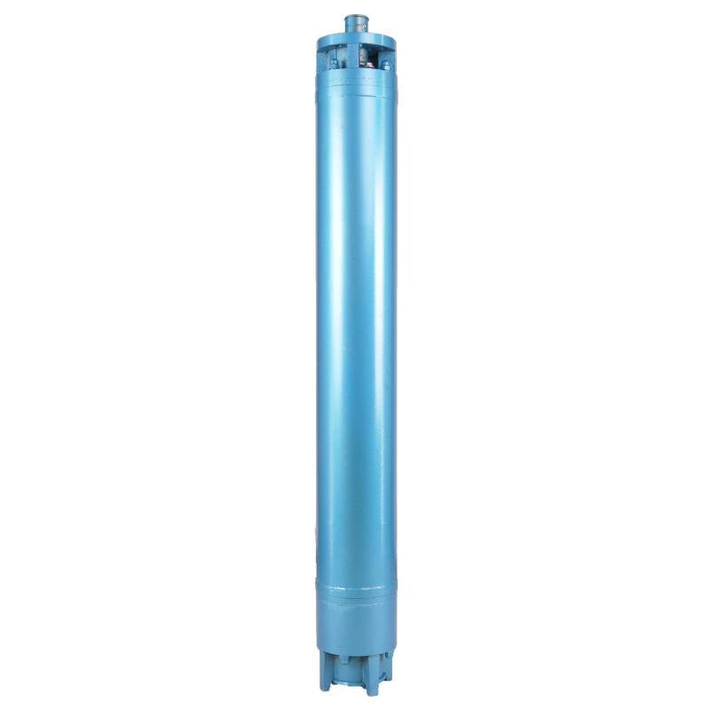
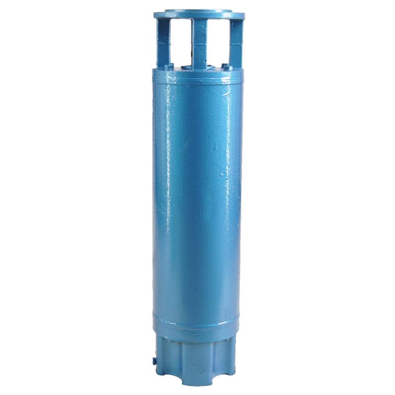
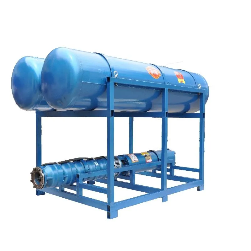
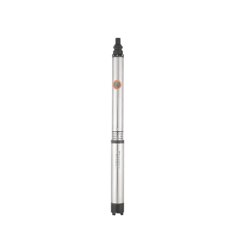
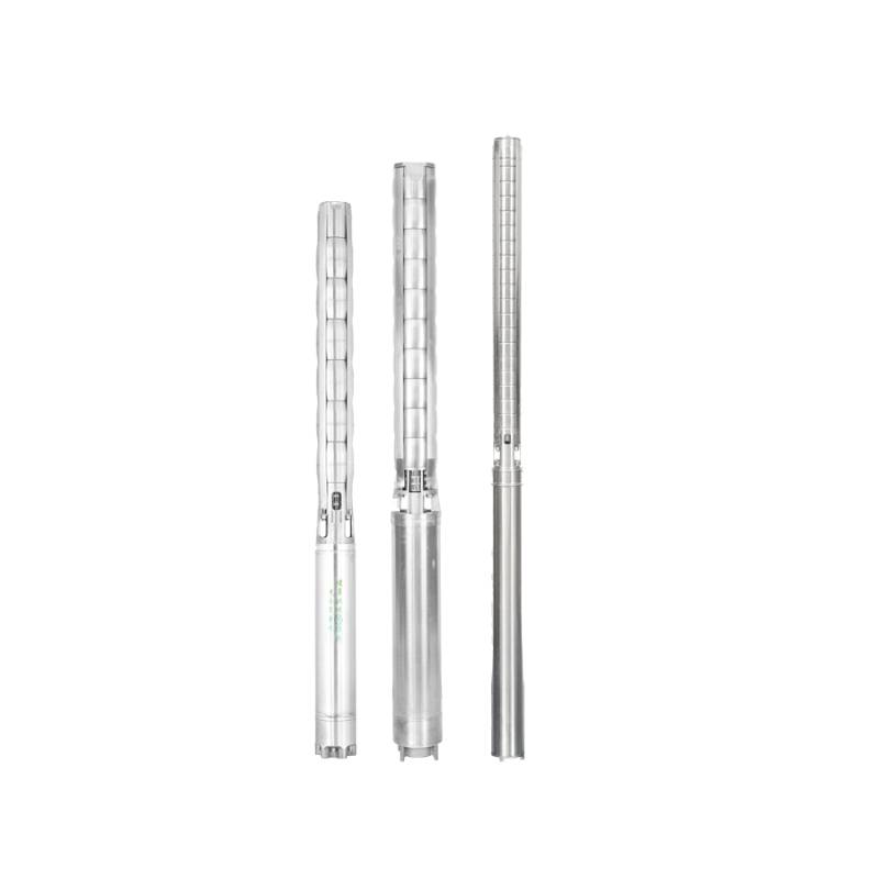
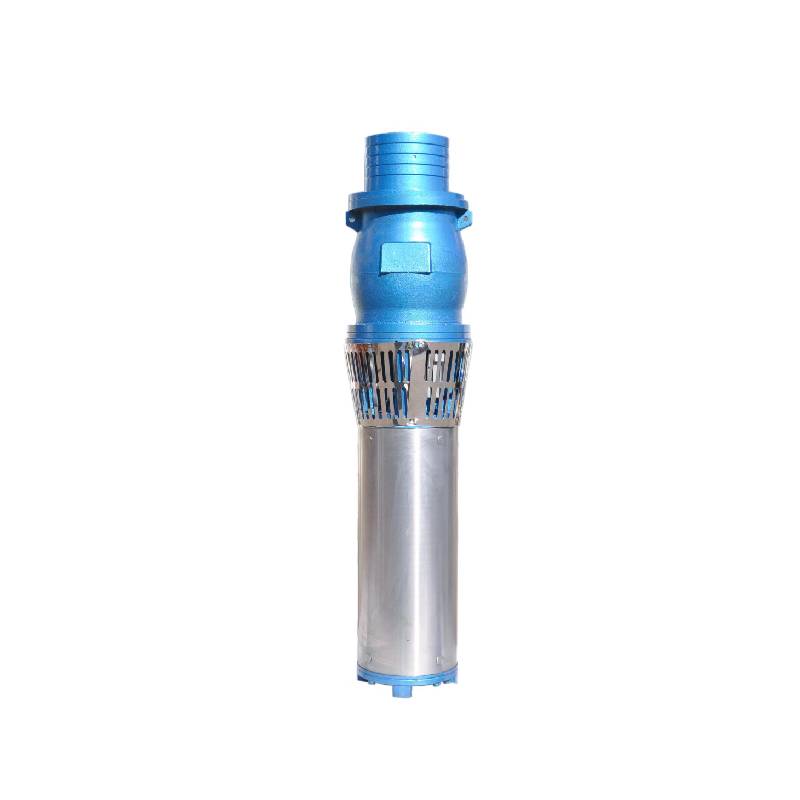
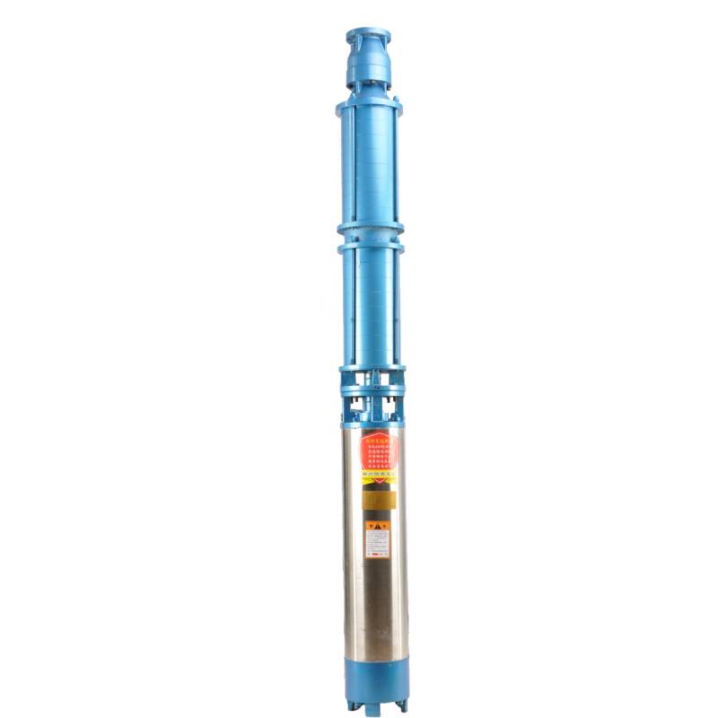
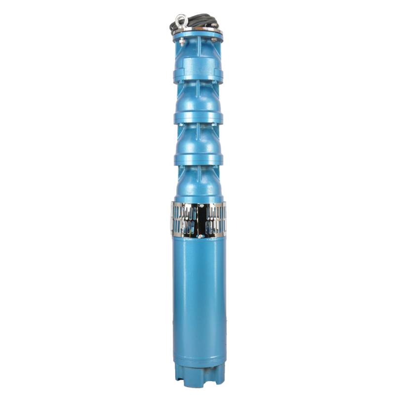
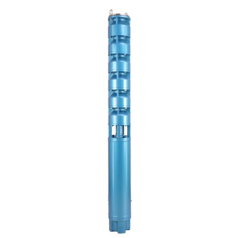
The product adopts special water-resistant wire for motor winding, with excellent characteristics such as high frequency shock resistance, pulse peak voltage shock resistance and high temperature aging resistance. The frequency conversion winding design ensures the motor to operate smoothly between 1Hz and 50Hz for a long time, making the frequency conversion deep well pump more energy saving and longer service life.
We are honored to introduce our products, this product provides three-phase AC 380V power supply (tolerance of ± 5%), 50HZ voltage (tolerance of ± 1%). At the same time, our products require strict water quality requirements: water temperature is not higher than 20 °C; solid impurities content (mass ratio) is not greater than 0.01%; PH value (pH) is 6.5-8.5; hydrogen sulfide content is not greater than 1.5mg/L; chloride ion content is not greater than 400mg/L. The motor adopts closed or water-filled wet structure, which must be filled with clean water before use to prevent empty. Tighten the water charging and deflating bolts before use, otherwise, it is not allowed to use. The submersible pump must be completely immersed in water to work, the immersion depth shall not exceed 70 meters, and the distance between the bottom of the submersible pump and the bottom of the well shall not be less than 3 meters. The well water flow shall meet the output and continuous operation requirements of the submersible pump, and the output of the submersible pump shall be controlled at 0.7-1.2 times of the rated flow. The well must be vertical, and the submersible pump can not be used horizontally or inverted, but only vertically. The submersible pump must be equipped with cables according to requirements, and is equipped with external overload protection devices. It is strictly prohibited to conduct no-load tests on the pump without water. Our products guarantee to provide you with high quality and stable performance, while meeting your needs to ensure safe and reliable.
| Model | Flow (m3/h) | Holle (m) |
Rotatingspeed (feroarje/punt) |
Wetterpomp(%) | Outlet diameter (mm) |
Goed tapast diameter (mm) |
Rated power(KW) |
Rated spanning (V) |
Rated aktuele (A) |
Motor effisjinsje (%) | power factorcosφ | Ienheid Radiale Maksimum grutte (mm) |
|||||||||
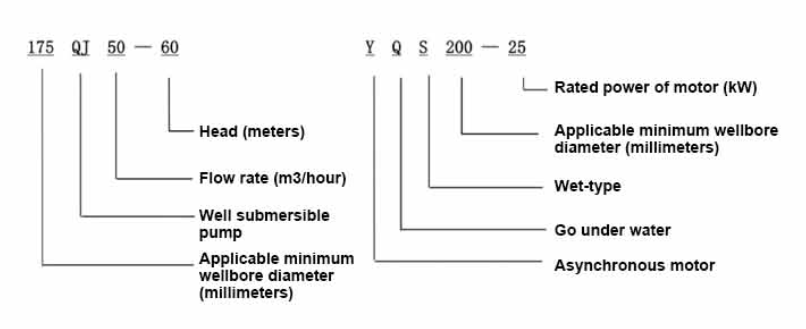
| 175QJ10-42 | 10 | 42 | 2850 | 53 | 50 | 175boppe | 3 | 380 | 7.8 | 74.0 | 0.79 | 168 | |||||||||
| 175QJ10-56 | 56 | 4 | 10.1 | 76.0 | 0.79 | ||||||||||||||||
| 175QJ10-70 | 70 | 4 | 10.1 | 76.0 | 0.79 | ||||||||||||||||
| 175QJ10-84 | 84 | 5.5 | 13.6 | 77.0 | 0.8 | ||||||||||||||||
| 175QJ10-112 | 112 | 7.5 | 18.4 | 77.5 | 0.8 | ||||||||||||||||
| 175QJ10-126 | 126 | 7.5 | 18.4 | 77.5 | 0.8 | ||||||||||||||||
| 175QJ10-140 | 140 | 9.2 | 22.1 | 78.0 | 0.81 | ||||||||||||||||
| 175QJ15-42 | 15 | 42 | 2850 | 58 | 50 | 175boppe | 4 | 380 | 10.1 | 76.0 | 0.79 | 168 | |||||||||
| 175QJ15-55 | 55 | 5.5 | 13.6 | 77.0 | 0.8 | ||||||||||||||||
| 175QJ15-65 | 65 | 5.5 | 13.6 | 77.0 | 0.8 | ||||||||||||||||
| 175QJ15-85 | 85 | 7.5 | 18.4 | 77.5 | 0.8 | ||||||||||||||||
| 175QJ15-112 | 112 | 9.2 | 22.1 | 78.0 | 0.81 | ||||||||||||||||
| 175QJ20-26 | 20 | 26 | 2850 | 64 | 50 | 175boppe | 3 | 380 | 7.8 | 74.0 | 0.79 | 168 | |||||||||
| 175QJ20-39 | 39 | 4 | 10.1 | 76.0 | 0.79 | ||||||||||||||||
| 175QJ20-52 | 52 | 5.5 | 13.6 | 77.0 | 0.8 | ||||||||||||||||
| 175QJ20-78 | 78 | 7.5 | 18.4 | 77.5 | 0.8 | ||||||||||||||||
| 175QJ20-91 | 91 | 9.2 | 22.1 | 78.0 | 0.81 | ||||||||||||||||
| 175QJ20-104 | 104 | 11 | 26.1 | 79.0 | 0.81 | ||||||||||||||||
| 175QJ20-130 | 130 | 13 | 30.1 | 80.0 | 0.82 | ||||||||||||||||
| 175QJ20-156 | 156 | 15 | 34.7 | 80.0 | 0.82 | ||||||||||||||||
| 175QJ20-182 | 187 | 18.5 | 42.6 | 80.5 | 0.82 | ||||||||||||||||
| 175QJ20-208 | 208 | 22 | 49.7 | 81.0 | 0.83 | ||||||||||||||||
| 175QJ20-247 | 247 | 25 | 56.5 | 81.0 | 0.83 | ||||||||||||||||
| 175QJ20-273 | 273 | 30 | 66.6 | 81.5 | 0.84 | ||||||||||||||||
| 175QJ20-299 | 299 | 30 | 66.6 | 81.5 | 0.84 | ||||||||||||||||
| 175QJ20-325 | 325 | 32 | 71.0 | 81.5 | 0.84 | ||||||||||||||||
| 175QJ20-364 | 364 | 37 | 82.1 | 81.5 | 0.84 | ||||||||||||||||
| 175QJ25-26 | 25 | 26 | 2850 | 66 | 65 | 175boppe | 3 | 380 | 7.8 | 74.0 | 0.79 | 168 | |||||||||
| 175QJ25-39 | 39 | 5.5 | 13.6 | 77.0 | 0.8 | ||||||||||||||||
| 175QJ25-65 | 25 | 65 | 2850 | 66 | 65 | 175boppe | 7.5 | 380 | 18.4 | 77.5 | 0.8 | 168 | |||||||||
| 175QJ25-78 | 78 | 9.2 | 22.1 | 78.0 | 0.81 | ||||||||||||||||
| 175QJ25-91 | 91 | 11 | 26.1 | 79.0 | 0.81 | ||||||||||||||||
| 175QJ25-104 | 104 | 13 | 30.1 | 80.0 | 0.82 | ||||||||||||||||
| 175QJ25-130 | 130 | 15 | 34.7 | 80.0 | 0.82 | ||||||||||||||||
| 175QJ25-156 | 156 | 18.5 | 42.6 | 80.5 | 0.82 | ||||||||||||||||
| 175QJ25-182 | 182 | 22 | 49.7 | 81.0 | 0.83 | ||||||||||||||||
| 175QJ25-208 | 208 | 25 | 56.5 | 81.0 | 0.83 | ||||||||||||||||
| 175QJ25-221 | 221 | 30 | 66.6 | 81.5 | 0.84 | ||||||||||||||||
| 175QJ25-247 | 247 | 30 | 66.6 | 81.5 | 0.84 | ||||||||||||||||
| 175QJ25-260 | 260 | 32 | 71.0 | 81.5 | 0.84 | ||||||||||||||||
| 175QJ25-299 | 299 | 37 | 82.1 | 81.5 | 0.84 | ||||||||||||||||
| 175QJ30-30 | 30 | 30 | 2850 | 67 | 80 | 175boppe | 4 | 380 | 10.1 | 76.0 | 0.79 | 168 | |||||||||
| 175QJ30-40 | 40 | 5.5 | 13.6 | 77.0 | 0.8 | ||||||||||||||||
| 175QJ32-24 | 32 | 24 | 2850 | 67 | 80 | 175boppe | 4 | 380 | 10.1 | 76.0 | 0.79 | 168 | |||||||||
| 175QJ32-36 | 36 | 5.5 | 13.6 | 77.0 | 0.8 | ||||||||||||||||
| 175QJ32-48 | 48 | 7.5 | 18.4 | 77.5 | 0.8 | ||||||||||||||||
| 175QJ32-60 | 60 | 9.2 | 22.1 | 78.0 | 0.81 | ||||||||||||||||
| 175QJ32-72 | 72 | 11 | 26.1 | 79.0 | 0.81 | ||||||||||||||||
| 175QJ32-84 | 84 | 13 | 30.1 | 80.0 | 0.82 | ||||||||||||||||
| 175QJ32-96 | 96 | 15 | 34.7 | 80.0 | 0.82 | ||||||||||||||||
| 175QJ32-120 | 120 | 18.5 | 42.6 | 80.5 | 0.82 | ||||||||||||||||
| 175QJ32-144 | 144 | 22 | 49.7 | 81.0 | 0.83 | ||||||||||||||||
| 175QJ32-168 | 168 | 25 | 56.5 | 81.0 | 0.83 | ||||||||||||||||
| 175QJ32-180 | 180 | 30 | 66.6 | 81.5 | 0.84 | ||||||||||||||||
| 175QJ32-192 | 192 | 30 | 66.6 | 81.5 | 0.84 | ||||||||||||||||
| 175QJ32-204 | 204 | 32 | 71.0 | 81.5 | 0.84 | ||||||||||||||||
| 175QJ32-240 | 240 | 37 | 82.1 | 81.5 | 0.84 | ||||||||||||||||
| 175QJ35-60 | 35 | 60 | 2850 | 67 | 80 | 175boppe | 10 | 380 | 25.0 | 78.0 | 0.78 | 168 | |||||||||
| 175QJ35-75 | 75 | 13 | 30.1 | 80.0 | 0.82 | ||||||||||||||||
| 175QJ35-100 | 100 | 17 | 40.9 | 80.0 | 0.79 | ||||||||||||||||
| 175QJ40-24 | 40 | 24 | 2850 | 70 | 80 | 175boppe | 5.5 | 380 | 13.6 | 77.0 | 0.8 | 168 | |||||||||
| 175QJ40-30 | 30 | 5.5 | 13.6 | 77.0 | 0.8 | ||||||||||||||||
| 175QJ40-36 | 36 | 7.5 | 18.4 | 77.5 | 0.8 | ||||||||||||||||
| 175QJ40-48 | 48 | 9.2 | 22.1 | 78.0 | 0.81 | ||||||||||||||||
| 175QJ40-60 | 60 | 11 | 26.1 | 79.0 | 0.81 | ||||||||||||||||
| 175QJ40-72 | 72 | 13 | 30.1 | 80.0 | 0.82 | ||||||||||||||||
| 175QJ40-84 | 84 | 15 | 34.7 | 80.0 | 0.82 | ||||||||||||||||
| 175QJ40-96 | 96 | 18.5 | 42.6 | 80.5 | 0.82 | ||||||||||||||||
| 175QJ40-120 | 120 | 22 | 49.7 | 81.0 | 0.83 | ||||||||||||||||
| 175QJ40-132 | 132 | 25 | 56.5 | 81.0 | 0.83 | ||||||||||||||||
| 175QJ40-144 | 144 | 30 | 66.6 | 81.5 | 0.84 | ||||||||||||||||
| 175QJ40-156 | 156 | 30 | 66.6 | 81.5 | 0.84 | ||||||||||||||||
| 175QJ40-168 | 168 | 32 | 71.0 | 81.5 | 0.84 | ||||||||||||||||
| 175QJ40-192 | 192 | 37 | 82.1 | 81.5 | 0.84 | ||||||||||||||||
| 175QJ50-24 | 50 | 24 | 2850 | 72 | 80 | 175boppe | 5.5 | 380 | 13.6 | 77.0 | 0.8 | 168 | |||||||||
| 175QJ50-36 | 36 | 9.2 | 22.1 | 78.0 | 0.81 | ||||||||||||||||
| 175QJ50-48 | 48 | 11 | 26.1 | 79.0 | 0.81 | ||||||||||||||||
| 175QJ50-60 | 60 | 13 | 30.1 | 80.0 | 0.82 | ||||||||||||||||
| 175QJ50-70 | 70 | 17 | 40.9 | 80.0 | 0.79 | ||||||||||||||||
| 175QJ50-84 | 84 | 18.5 | 42.6 | 80.5 | 0.82 | ||||||||||||||||
| 175QJ50-96 | 96 | 22 | 49.7 | 81.0 | 0.83 | ||||||||||||||||
| 175QJ50-108 | 108 | 25 | 56.5 | 81.0 | 0.83 | ||||||||||||||||
| 175QJ50-120 | 120 | 30 | 66.6 | 81.5 | 0.84 | ||||||||||||||||
| 175QJ50-132 | 132 | 30 | 66.6 | 81.5 | 0.84 | ||||||||||||||||
| 175QJ50-144 | 144 | 32 | 71.0 | 81.5 | 0.84 | ||||||||||||||||
| 175QJ50-156 | 156 | 37 | 82.1 | 81.5 | 0.84 | ||||||||||||||||
| 175QJ63-22 | 63 | 22 | 2850 | 72 | 80 | 175boppe | 7.5 | 380 | 18.4 | 77.5 | 0.8 | 168 | |||||||||
| 175QJ63-44 | 44 | 13 | 30.1 | 80.0 | 0.82 | ||||||||||||||||
| 175QJ63-55 | 55 | 15 | 34.7 | 80.0 | 0.82 | ||||||||||||||||
| 175QJ63-66 | 66 | 18.5 | 42.6 | 80.5 | 0.82 | ||||||||||||||||
| 175QJ63-77 | 77 | 22 | 49.7 | 81.0 | 0.83 | ||||||||||||||||
| 175QJ63-88 | 88 | 25 | 56.5 | 81.0 | 0.83 | ||||||||||||||||
| 175QJ63-99 | 63 | 99 | 2850 | 72 | 80 | 175boppe | 30 | 380 | 66.6 | 81.5 | 0.84 | 168 | |||||||||
| 175QJ63-110 | 110 | 32 | 71.0 | 81.5 | 0.84 | ||||||||||||||||
| 175QJ63-132 | 132 | 37 | 82.1 | 81.5 | 0.84 | ||||||||||||||||
| 175QJ80-9 | 80 | 9 | 2850 | 73 | 100 | 175boppe | 4 | 380 | 10.1 | 76.0 | 0.79 | 168 | |||||||||
| 175QJ80-18 | 18 | 7.5 | 18.4 | 77.5 | 0.8 | ||||||||||||||||
| 175QJ80-27 | 27 | 11 | 26.1 | 79.0 | 0.81 | ||||||||||||||||
| 175QJ80-36 | 36 | 15 | 34.7 | 80.0 | 0.82 | ||||||||||||||||
| 175QJ80-45 | 45 | 18.5 | 42.6 | 80.5 | 0.82 | ||||||||||||||||
| 175QJ80-54 | 54 | 22 | 49.7 | 81.0 | 0.83 | ||||||||||||||||
| 175QJ80-63 | 63 | 25 | 56.5 | 81.0 | 0.83 | ||||||||||||||||
| 175QJ80-72 | 72 | 25 | 56.5 | 81.0 | 0.83 | ||||||||||||||||
| 175QJ80-81 | 81 | 30 | 66.6 | 81.5 | 0.84 | ||||||||||||||||
| 175QJ80-90 | 90 | 32 | 71.0 | 81.5 | 0.84 | ||||||||||||||||
| 175QJ80-98 | 98 | 37 | 82.1 | 81.5 | 0.84 | ||||||||||||||||
This well submersible pump is a pump suitable for clean water. Digging new wells and pumping sediment and turbid water are strictly prohibited. The voltage grade of the well pump is 380V/50HZ. Submersible motors with other voltage grades need to be customized. Underground cables must use waterproof cables and must be equipped with starting equipment, such as distribution boxes, etc. The starting equipment should have common comprehensive motor protection functions, such as overload short circuit protection, phase loss protection, undervoltage protection, grounding protection and idling protection, etc. In abnormal cases, the protection device should be tripped in time. During installation and use, the pump must be reliably grounded. It is prohibited to push and pull the switch when hands and feet are wet. The power supply must be cut off before installation and maintenance of the pump. The place where the pump is used must be set up with obvious "anti-electric shock" marks. Before going down the well or installation, the motor must be injected with distilled water or non-corrosive clear cold water in the inner cavity, and the intake/drain bolts must be tightened. When testing the pump on the ground, water must be injected into the pump chamber to lubricate the rubber bearings. The instant start time should not exceed one second to check whether the direction is correct. The same as the steering instructions. Pay attention to safety when the pump is upright to prevent tilting and injury. Strictly in accordance with the provisions of the pump lift and flow range, to prevent the pump flow at low lift or in high lift pull too large, resulting in extreme wear of thrust bearings and other components, the motor due to overload and burn. After put into the well, the measurement of the motor and the ground insulation resistance value, not less than 100M. After the start, regular observation of voltage and current, and check the motor winding insulation is in line with the requirements of the provisions. If the temperature of the storage site is below the freezing point, the water in the pump chamber should be drained to prevent the water in the motor chamber from freezing and damaging the motor due to low temperature.
Koarte yntroduksje fan struktuer: pomp diel is benammen gearstald út pomp skacht, waaier, omlieding shell, rubber bearing, check fentyl lichem (opsjoneel dielen) en oare komponinten. Motor diel is benammen gearstald út basis, druk regulearjende film, thrust bearing, thrust plaat, legere gids lager sit, stator, rotor, boppeste gids lager sit, sân ring, wetter ynlaat seksje, kabel en oare komponinten.
De wichtichste skaaimerken fan it produkt binne:
1.The motor is a water-filled wet submersible three-phase asynchronous motor, the motor cavity is full of clean water, used to cool the motor and lubricate the bearing, the pressure regulating film at the bottom of the motor is used to adjust the expansion and contraction pressure difference of the water inside the body caused by the change of the temperature rise of the motor.
2.In order to prevent the sand in the well water from entering the motor, the upper end of the motor shaft is equipped with two oil seals, and a sand ring is installed to form a sand prevention structure.
3.In order to prevent the pump shaft from running up when starting, the pump shaft and the motor shaft are connected by a coupling, and an upper thrust bearing is installed at the lower part of the motor.
4.The lubrication of the motor and the pump bearing is water lubrication.
5.The motor stator winding is made of high quality submersible motor winding wire, with high insulation performance.
6.The pump is designed by computer CAD, with simple structure and good technical performance.

(1) Tarieding foar ynstallaasje:
1. Kontrolearje oft de dompelpomp foldocht oan de gebrûksbetingsten en omfang spesifisearre yn 'e hantlieding.
2. Mei in swiere objekt mei in diameter lyk oan de maksimale bûtendiameter fan 'e dompelpomp, mjitte oft de binnendiameter fan' e putboring de dompelpomp passe kin, en mjit oft de putdjipte foldocht oan de ynstallaasjeeasken.
3. Kontrolearje oft de putboring skjin is en oft it putwetter troebel is. Nea brûke in dompelpomp elektryske pomp te waskjen de welor pomp modder en sân wetter te kommen foar betiid skea oan de dompelpomp elektryske pomp.
4. Kontrolearje oft de posysje fan de welhead ynstallaasje clamp is geskikt en oft it kin wjerstean de kwaliteit fan de hiele ienheid
5. Kontrolearje oft de submersible pomp ûnderdielen binne kompleet en ynstallearre goed neffens de gearstalling diagram yn de hânlieding Ferwiderje it filter skerm en draaie de koppeling om te sjen oft it draait fleksibel
6. Skroef de wetterskroef los en folje de motorholte mei skjin, net-korrosyf wetter (notysje. Wês wis dat it opfolje), dan draait de wetterskroef oan. Nei 12 oeren fan wetterynjeksje moat de isolaasjeferset fan 'e motor net minder wêze dan 150M Q as mjitten mei in 500V skoddetafel.
7. Cable joint, cut off a 120mm rubber sleeve from one end of the outgoing cable and the matching cable with an electrician's knifethen stagger the length of the three core wires in a stepped shape, peel off a 20mm copper core, scrape of the oxide layer on theoutside of the copper wire with a knife or sand cloth, and insert the two connected wire ends in palirs.After tying the layer tightly with fine copper wire, solder it thoroughly and firmly, and sand of any. burrs on the surface. Then, forthe three joints, use polyvester insulation tape to wrap them in a semi stacked manner for three lavers. Wrap the two ends of thewrapping layer tightywith nyion thread,and then use a semi stacked method to wrap the tape for three layers. Wrap the outellayer with high-pressure insulation tape for three layers. Finally, fold the threestrands together and repeatedly wrap them for fivelayers with high-pressure tape. Each layer must be tightly tied, and the interlayer joints must be tight and fimm to prevent water frompenetrating and damaging the insulation, After wrapping, soak in water at room temperature of 20 ’c for 12 hours, and measurethe insulation resistance with a shaking table, which should not be less than 100M Ω
It taheakke prosesdiagram foar kabelbedrading is as folget: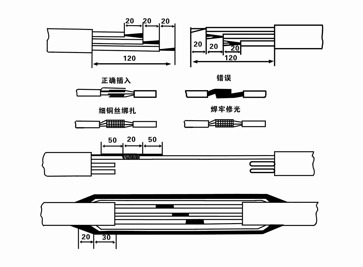
8. Brûk in multimeter om te kontrolearjen oft de trije-fase triedden binne ferbûn en oft de DC ferset is likernôch lykwichtich.
9. Kontrolearje oft it circuit en transformator kapasiteit binne oerladen, en dan ferbinen de oerlêst beskerming switch of begjinnende apparatuer. Sjoch Tabel 2 foar spesifike modellen, en dan Giet in amer mei wetter yn 'e wetterpomp út' e wetterpompútlaat om de rubberlagers yn 'e pomp te smeerjen, en set dan de ûnderdompelbere elektryske pomp rjochtop en steady.Start (net mear as ien sekonde) en kontrolearje oft de stjoerrjochting oerienkomt mei it stjoerteken. As net, ruilje alle twa Anschlüsse fan 'e trije-faze kabel. Ynstallearje dan it filter en meitsje jo klear om de put del te gean. As brûkt by spesjale gelegenheden (lykas sleatten, sleatten, rivieren, fivers, fivers, ensfh.), De elektryske pomp moat betrouber wurde grûn.
(2) Ynstallaasje apparatuer en ark:
1. Ien pear liftkeatlingen foar mear as twa ton.
2. In tripod mei in fertikale hichte fan net minder as fjouwer meter.
3. Twa hingjende touwen (wire touwen) dy't in gewicht fan mear as ien ton drage kinne (kinne it gewicht fan in folsleine set wetterpompen drage).
4. Ynstallearje twa pearen fan clamps (spalken).
5. Wrenches, hammers, schroevendraaiers, elektryske ark en ynstruminten, ensfh.
(3) Elektryske pomp ynstallaasje:
1. It ynstallaasjediagram fan 'e ûnderdompele elektryske pomp wurdt werjûn yn figuer 2. De spesifike ynstallaasjedimensjes wurde werjûn yn Tabel 3 "List fan ynstallaasje-ôfmjittings fan 'e ûnderdompele elektryske pomp".
2. Submersible elektryske pompen mei in kop minder as 30 meter kinne direkt yn 'e boarne ophelle wurde mei slangen en draadseilen of oare himp-touwen dy't it folsleine gewicht fan' e hiele masine, wetterpipes, en wetter yn 'e pipes drage kinne.
3. Pompen mei in kop fan mear as 30 meter brûke stielen pipen, en de ynstallaasje folchoarder is as folget:
①Gebrûk in klem om it boppeste ein fan it wetterpompdiel te klemmen (de motor en de wetterpomp binne op dit stuit ferbûn), til it mei in hingjende keatling op en bine it stadichoan yn 'e put oant Set de klem op' e putkop en fuortsmite hingjende ketting.
② Brûk in oar pear klemmen om in piip te klemmen, til it mei in hingjende ketting 15 sm fuort fan 'e flange, en ferleegje it stadich. Tusken pipe flange en pomp flangePut de rubberen pad yn plak en strak de piip en pomp gelyk mei bouten, moeren en spring washers.
③ Til de dompelpomp in bytsje op, ferwiderje de klem op 'e boppeste ein fan' e wetterpomp, bine de kabel stevich oan 'e wetterpipe mei in plestik tape, en bûgje it stadichoan oant De klem wurdt pleatst by de putkop.
④Brûk deselde metoade om alle wetterpipes yn 'e put te binen.
⑤ Neidat de lead-out kabel is ferbûn mei de kontrôle switch, it is ferbûn oan de trije-fase Netzteil.
(4) Dingen om op te merken by ynstallaasje:
1. As in jamming ferskynsel wurdt fûn tidens it pompen proses, draaie of lûke de wetter piip te oerwinnen it jamming punt. As ferskate maatregels noch net wurkje, twinge asjebleaft de pomp net omleech om skea oan 'e dompelpomp en de put te foarkommen.
2. By ynstallaasje moat in rubberen pad op 'e flange fan elke piip pleatst wurde en gelijkmatig oanskerpe.
3. As de wetterpomp yn 'e boarne ferlege wurdt, moat it yn' e midden fan 'e putpipe pleatst wurde om te foarkommen dat de pomp lang tsjin' e wellmuorre rint, wêrtroch't de pomp trillet en de motor sweep en brânt .
4. Bepale de djipte fan 'e wetterpomp nei de boaiem fan' e boarne neffens de streamende sân- en siltbetingsten fan 'e boarne. Begrave de pomp net yn 'e modder. De ôfstân fan 'e wetterpomp nei de boaiem fan' e put is oer it generaal net minder as 3 meter (sjoch figuer 2).
5. De wetteryngongsdjipte fan 'e wetterpomp moat net minder wêze as 1-1,5 meter fan it dynamyske wetterpeil nei it wetteryntreeknooppunt (sjoch figuer 2). Oars kinne de wetterpomplagers maklik skea wurde.
6. De lift fan 'e wetterpomp kin net te leech wêze. Oars, in poarte fentyl moat wurde ynstallearre op de wellhead wetter pipeline te kontrolearjen de pomp trochstreaming op de rated flow punt om foar te kommen dat de motor wurdt oerladen en útbaarnd fanwege grutte stream tariven.
7. As de wetterpomp rint, moat de wetterútfier kontinuële en sels wêze, de aktuele moat stabyl wêze (ûnder beoardielde wurkomstannichheden, oer it generaal net mear as 10% fan 'e nominearre aktuele), en der moat gjin trilling of lûd wêze. As der in abnormaliteit is, moat de masine wurde stoppe om de oarsaak te finen en it te eliminearjen.
8. By it ynstallearjen, betelje omtinken oan de ynstelling fan 'e motor grûndraad (sjoch figuer 2). As it wetter piip is in stielen piip, liedt it út de puthead clamp; as it wetter piip is in plestik piip, liedt it út 'e grûn mark fan' e elektryske pomp.
- 1.After installing the submersible pump, recheck the insulation resistance and three-phase continuity switch, check whether there is any error in the connection between the instrument and the starting equipment.If there is no problem, you can start to test the machine. After starting, observe whether the indication reading of each instrument is correct.If the rated voltage and current specified on the nameplate are exceeded, please observe whether the pump has noise or vibration.If everything is normal, it can be put into operation. After the pump runs for the first time for four hours, the motor thermal insulation resistance should be closed and tested quickly. Its value should not be less than 0.5 megaohm. After the pump stops, it should be restarted after five minutes to prevent the water column in the pipeline from completely reversing, which will cause the motor to burn out due to excessive current.
- 2.After the pump is put into normal operation, in order to prolong its service life, it is necessary to check whether the supply voltage, working current and insulation resistance are normal regularly. If the following conditions are found, the machine should be stopped immediately to troubleshoot.
- 1.Under the rated working condition, the current exceeds 20%.
- 2.The dynamic water level drops to the water inlet section, resulting in intermittent water.
- 3.The submersible pump has severe vibration or noise.
- 4.The supply voltage is lower than 340 volts.
- 5.A fuse is burned out.
- 6.The water pipeline is damaged.
- 7.The motor's insulation resistance to the geothermal state is lower than 0.5 megaohm.
- 3.Unit disassembly:
- - Untie de kabel tie, fuortsmite de pipeline diel, en fuortsmite de tried plaat.
- - screw down the water bolt, put out the water in the motor chamber.
- - it filter fuortsmite, de fêste skroef op 'e koppeling losmeitsje om de motoras te befestigjen.
- 4.screw down the bolt connecting the water inlet section with the motor, and separate the pump from the motor (pay attention to the unit cushion when separating, to prevent the bending of the pump shaft)
- 5.the disassembly sequence of the pump is: (see figure 1) water inlet section, impeller, diversion shell, impeller...... check valve body, when removing the impeller, use special tools to loosen the conical sleeve of the fixed impeller first, and avoid bending and bruising the pump shaft in the process of disassembly.
- 6.the disassembly process of the motor is: (see figure 1) place the motor on the platform, and remove the nuts, base, shaft head locking nut, thrust plate, key, lower guide bearing seat and double head bolt from the bottom of the motor in turn, and then take out the rotor (pay attention not to damage the wire package) and finally remove the connecting section and upper guide bearing seat.
- 7.unit assembly: before assembly, the rust and dirt of the parts should be cleaned, and the mating surface and fasteners coated with sealant, and then assembled in the opposite order of disassembly (the motor shaft moves up and down after assembly for about one millimeter), after assembly, the coupling should be flexible, and then the filter screen test machine. Submersible pumps shall be taken out of the well for dismantling and maintenance according to Article 5 after a year of operation, or less than a year of operation but two years of diving time, and the worn parts shall be replaced.
1, set it wetter yn 'e motorholte (benammen yn' e winter om foar te kommen dat de motor befriest), en bine de kabel goed.
2, store in an indoor room without corrosive substances and gases, with a temperature below 40 °C.
3, lange-termyn gebrûk moatte betelje omtinken foar de roest previnsje fan dompelpompen.
- Impeller
- Shaft mouwe
- Rubber shaft sleeve
-
Segelring
01 Djippe boarne wetter yntak
02 Hege wetterfoarsjenning
03 berch wetterfoarsjenning
04 toer wetter
05 Agraryske yrrigaasje
06 tún yrrigaasje
07 rivier wetter yntak
08 húshâldlik wetter


