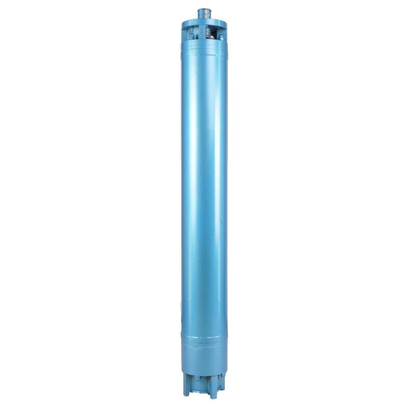
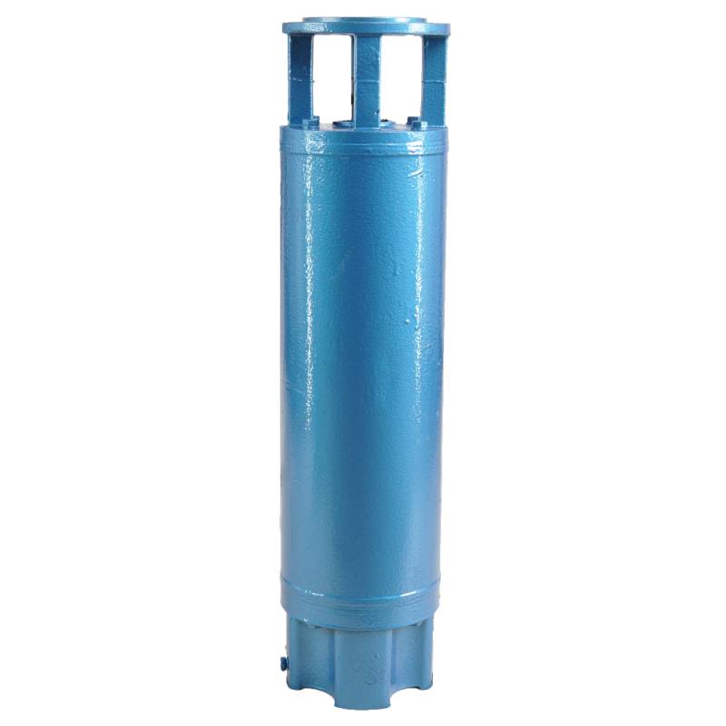
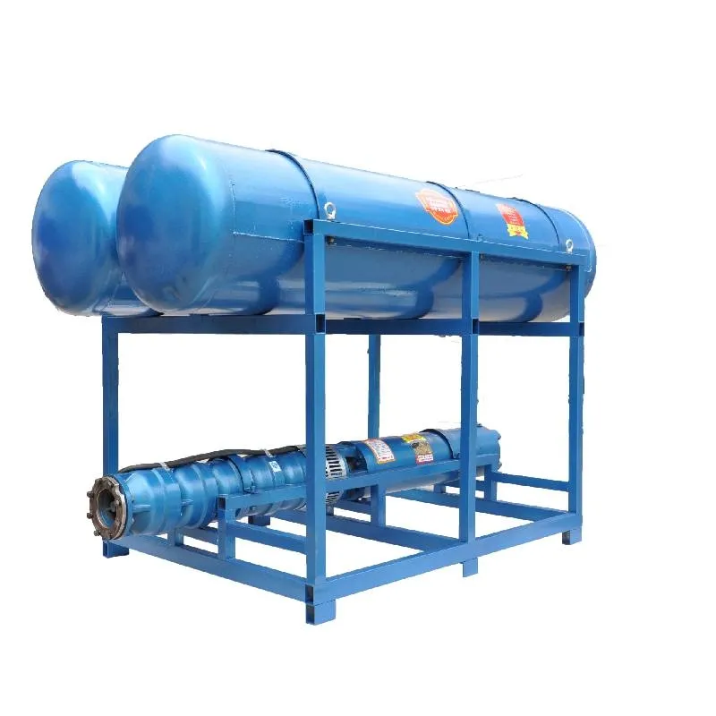
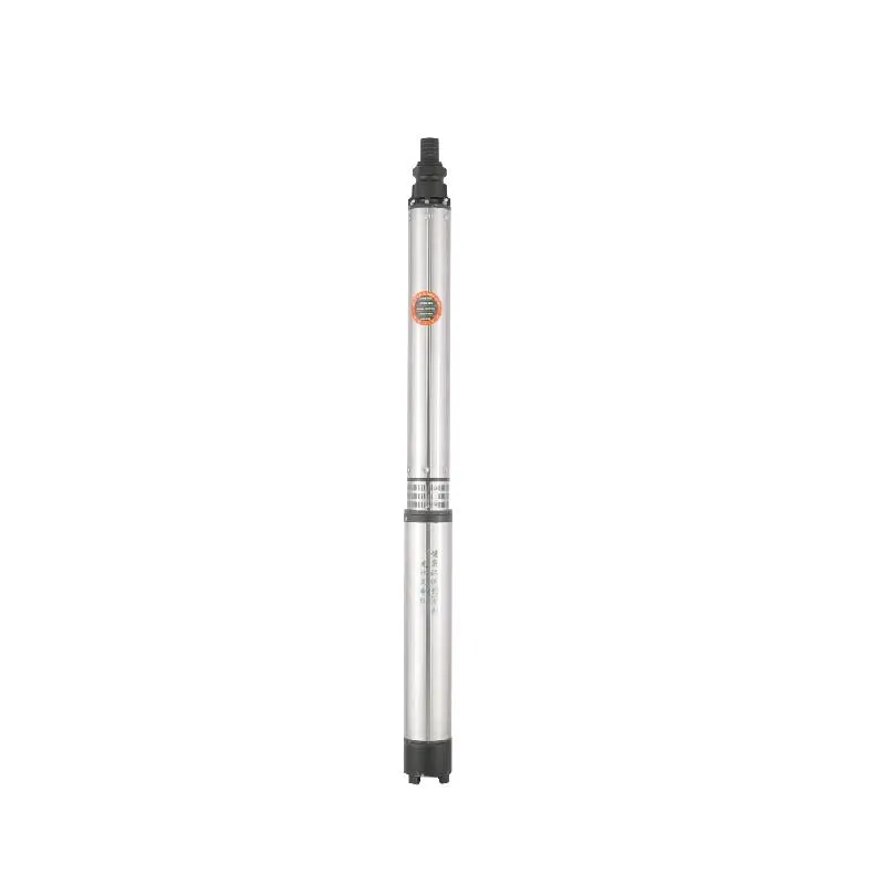
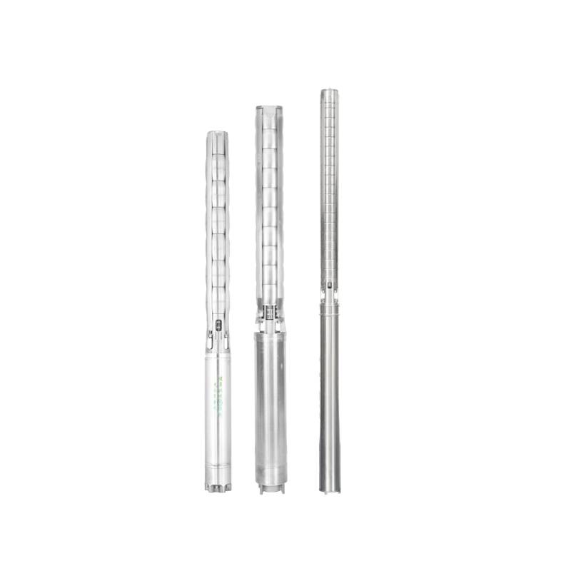
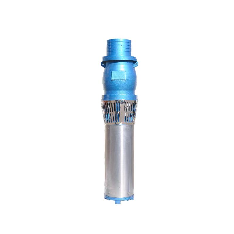
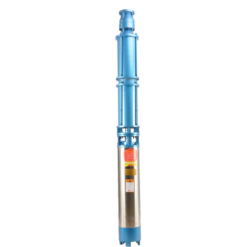
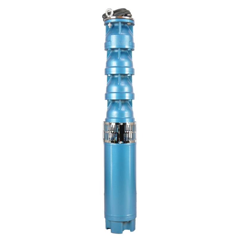
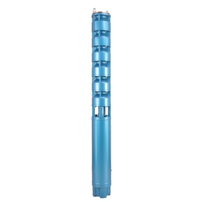
The product adopts special water-resistant wire for motor winding, with excellent characteristics such as high frequency shock resistance, pulse peak voltage shock resistance and high temperature aging resistance. The frequency conversion winding design ensures the motor to operate smoothly between 1Hz and 50Hz for a long time, making the frequency conversion deep well pump more energy saving and longer service life.
We are honored to introduce our products, this product provides three-phase AC 380V power supply (tolerance of ± 5%), 50HZ voltage (tolerance of ± 1%). At the same time, our products require strict water quality requirements: water temperature is not higher than 20 °C; solid impurities content (mass ratio) is not greater than 0.01%; PH value (pH) is 6.5-8.5; hydrogen sulfide content is not greater than 1.5mg/L; chloride ion content is not greater than 400mg/L. The motor adopts closed or water-filled wet structure, which must be filled with clean water before use to prevent empty. Tighten the water charging and deflating bolts before use, otherwise, it is not allowed to use. The submersible pump must be completely immersed in water to work, the immersion depth shall not exceed 70 meters, and the distance between the bottom of the submersible pump and the bottom of the well shall not be less than 3 meters. The well water flow shall meet the output and continuous operation requirements of the submersible pump, and the output of the submersible pump shall be controlled at 0.7-1.2 times of the rated flow. The well must be vertical, and the submersible pump can not be used horizontally or inverted, but only vertically. The submersible pump must be equipped with cables according to requirements, and is equipped with external overload protection devices. It is strictly prohibited to conduct no-load tests on the pump without water. Our products guarantee to provide you with high quality and stable performance, while meeting your needs to ensure safe and reliable.
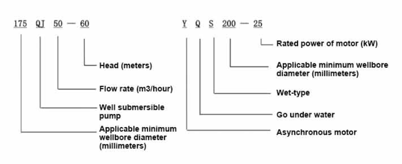
| Fyrirmynd | Rennsli (m3/klst.) | Höfuð (m) |
Snúningshraði (breyting/punktur) |
Vatns pumpa(%) | Útrás þvermál (mm) |
Gildir vel þvermál (mm) |
Metið power(KW) |
Metið spenna (V) |
Metið straumur (A) |
Mótorafköst (%) | power factorcosφ | Eining Radial Maximu stærð (mm) |
|||||||||
| 175QJ10-42 | 10 | 42 | 2850 | 53 | 50 | 175hér að ofan | 3 | 380 | 7.8 | 74.0 | 0.79 | 168 | |||||||||
| 175QJ10-56 | 56 | 4 | 10.1 | 76.0 | 0.79 | ||||||||||||||||
| 175QJ10-70 | 70 | 4 | 10.1 | 76.0 | 0.79 | ||||||||||||||||
| 175QJ10-84 | 84 | 5.5 | 13.6 | 77.0 | 0.8 | ||||||||||||||||
| 175QJ10-112 | 112 | 7.5 | 18.4 | 77.5 | 0.8 | ||||||||||||||||
| 175QJ10-126 | 126 | 7.5 | 18.4 | 77.5 | 0.8 | ||||||||||||||||
| 175QJ10-140 | 140 | 9.2 | 22.1 | 78.0 | 0.81 | ||||||||||||||||
| 175QJ15-42 | 15 | 42 | 2850 | 58 | 50 | 175hér að ofan | 4 | 380 | 10.1 | 76.0 | 0.79 | 168 | |||||||||
| 175QJ15-55 | 55 | 5.5 | 13.6 | 77.0 | 0.8 | ||||||||||||||||
| 175QJ15-65 | 65 | 5.5 | 13.6 | 77.0 | 0.8 | ||||||||||||||||
| 175QJ15-85 | 85 | 7.5 | 18.4 | 77.5 | 0.8 | ||||||||||||||||
| 175QJ15-112 | 112 | 9.2 | 22.1 | 78.0 | 0.81 | ||||||||||||||||
| 175QJ20-26 | 20 | 26 | 2850 | 64 | 50 | 175hér að ofan | 3 | 380 | 7.8 | 74.0 | 0.79 | 168 | |||||||||
| 175QJ20-39 | 39 | 4 | 10.1 | 76.0 | 0.79 | ||||||||||||||||
| 175QJ20-52 | 52 | 5.5 | 13.6 | 77.0 | 0.8 | ||||||||||||||||
| 175QJ20-78 | 78 | 7.5 | 18.4 | 77.5 | 0.8 | ||||||||||||||||
| 175QJ20-91 | 91 | 9.2 | 22.1 | 78.0 | 0.81 | ||||||||||||||||
| 175QJ20-104 | 104 | 11 | 26.1 | 79.0 | 0.81 | ||||||||||||||||
| 175QJ20-130 | 130 | 13 | 30.1 | 80.0 | 0.82 | ||||||||||||||||
| 175QJ20-156 | 156 | 15 | 34.7 | 80.0 | 0.82 | ||||||||||||||||
| 175QJ20-182 | 187 | 18.5 | 42.6 | 80.5 | 0.82 | ||||||||||||||||
| 175QJ20-208 | 208 | 22 | 49.7 | 81.0 | 0.83 | ||||||||||||||||
| 175QJ20-247 | 247 | 25 | 56.5 | 81.0 | 0.83 | ||||||||||||||||
| 175QJ20-273 | 273 | 30 | 66.6 | 81.5 | 0.84 | ||||||||||||||||
| 175QJ20-299 | 299 | 30 | 66.6 | 81.5 | 0.84 | ||||||||||||||||
| 175QJ20-325 | 325 | 32 | 71.0 | 81.5 | 0.84 | ||||||||||||||||
| 175QJ20-364 | 364 | 37 | 82.1 | 81.5 | 0.84 | ||||||||||||||||
| 175QJ25-26 | 25 | 26 | 2850 | 66 | 65 | 175hér að ofan | 3 | 380 | 7.8 | 74.0 | 0.79 | 168 | |||||||||
| 175QJ25-39 | 39 | 5.5 | 13.6 | 77.0 | 0.8 | ||||||||||||||||
| 175QJ25-65 | 25 | 65 | 2850 | 66 | 65 | 175hér að ofan | 7.5 | 380 | 18.4 | 77.5 | 0.8 | 168 | |||||||||
| 175QJ25-78 | 78 | 9.2 | 22.1 | 78.0 | 0.81 | ||||||||||||||||
| 175QJ25-91 | 91 | 11 | 26.1 | 79.0 | 0.81 | ||||||||||||||||
| 175QJ25-104 | 104 | 13 | 30.1 | 80.0 | 0.82 | ||||||||||||||||
| 175QJ25-130 | 130 | 15 | 34.7 | 80.0 | 0.82 | ||||||||||||||||
| 175QJ25-156 | 156 | 18.5 | 42.6 | 80.5 | 0.82 | ||||||||||||||||
| 175QJ25-182 | 182 | 22 | 49.7 | 81.0 | 0.83 | ||||||||||||||||
| 175QJ25-208 | 208 | 25 | 56.5 | 81.0 | 0.83 | ||||||||||||||||
| 175QJ25-221 | 221 | 30 | 66.6 | 81.5 | 0.84 | ||||||||||||||||
| 175QJ25-247 | 247 | 30 | 66.6 | 81.5 | 0.84 | ||||||||||||||||
| 175QJ25-260 | 260 | 32 | 71.0 | 81.5 | 0.84 | ||||||||||||||||
| 175QJ25-299 | 299 | 37 | 82.1 | 81.5 | 0.84 | ||||||||||||||||
| 175QJ30-30 | 30 | 30 | 2850 | 67 | 80 | 175hér að ofan | 4 | 380 | 10.1 | 76.0 | 0.79 | 168 | |||||||||
| 175QJ30-40 | 40 | 5.5 | 13.6 | 77.0 | 0.8 | ||||||||||||||||
| 175QJ32-24 | 32 | 24 | 2850 | 67 | 80 | 175hér að ofan | 4 | 380 | 10.1 | 76.0 | 0.79 | 168 | |||||||||
| 175QJ32-36 | 36 | 5.5 | 13.6 | 77.0 | 0.8 | ||||||||||||||||
| 175QJ32-48 | 48 | 7.5 | 18.4 | 77.5 | 0.8 | ||||||||||||||||
| 175QJ32-60 | 60 | 9.2 | 22.1 | 78.0 | 0.81 | ||||||||||||||||
| 175QJ32-72 | 72 | 11 | 26.1 | 79.0 | 0.81 | ||||||||||||||||
| 175QJ32-84 | 84 | 13 | 30.1 | 80.0 | 0.82 | ||||||||||||||||
| 175QJ32-96 | 96 | 15 | 34.7 | 80.0 | 0.82 | ||||||||||||||||
| 175QJ32-120 | 120 | 18.5 | 42.6 | 80.5 | 0.82 | ||||||||||||||||
| 175QJ32-144 | 144 | 22 | 49.7 | 81.0 | 0.83 | ||||||||||||||||
| 175QJ32-168 | 168 | 25 | 56.5 | 81.0 | 0.83 | ||||||||||||||||
| 175QJ32-180 | 180 | 30 | 66.6 | 81.5 | 0.84 | ||||||||||||||||
| 175QJ32-192 | 192 | 30 | 66.6 | 81.5 | 0.84 | ||||||||||||||||
| 175QJ32-204 | 204 | 32 | 71.0 | 81.5 | 0.84 | ||||||||||||||||
| 175QJ32-240 | 240 | 37 | 82.1 | 81.5 | 0.84 | ||||||||||||||||
| 175QJ35-60 | 35 | 60 | 2850 | 67 | 80 | 175hér að ofan | 10 | 380 | 25.0 | 78.0 | 0.78 | 168 | |||||||||
| 175QJ35-75 | 75 | 13 | 30.1 | 80.0 | 0.82 | ||||||||||||||||
| 175QJ35-100 | 100 | 17 | 40.9 | 80.0 | 0.79 | ||||||||||||||||
| 175QJ40-24 | 40 | 24 | 2850 | 70 | 80 | 175hér að ofan | 5.5 | 380 | 13.6 | 77.0 | 0.8 | 168 | |||||||||
| 175QJ40-30 | 30 | 5.5 | 13.6 | 77.0 | 0.8 | ||||||||||||||||
| 175QJ40-36 | 36 | 7.5 | 18.4 | 77.5 | 0.8 | ||||||||||||||||
| 175QJ40-48 | 48 | 9.2 | 22.1 | 78.0 | 0.81 | ||||||||||||||||
| 175QJ40-60 | 60 | 11 | 26.1 | 79.0 | 0.81 | ||||||||||||||||
| 175QJ40-72 | 72 | 13 | 30.1 | 80.0 | 0.82 | ||||||||||||||||
| 175QJ40-84 | 84 | 15 | 34.7 | 80.0 | 0.82 | ||||||||||||||||
| 175QJ40-96 | 96 | 18.5 | 42.6 | 80.5 | 0.82 | ||||||||||||||||
| 175QJ40-120 | 120 | 22 | 49.7 | 81.0 | 0.83 | ||||||||||||||||
| 175QJ40-132 | 132 | 25 | 56.5 | 81.0 | 0.83 | ||||||||||||||||
| 175QJ40-144 | 144 | 30 | 66.6 | 81.5 | 0.84 | ||||||||||||||||
| 175QJ40-156 | 156 | 30 | 66.6 | 81.5 | 0.84 | ||||||||||||||||
| 175QJ40-168 | 168 | 32 | 71.0 | 81.5 | 0.84 | ||||||||||||||||
| 175QJ40-192 | 192 | 37 | 82.1 | 81.5 | 0.84 | ||||||||||||||||
| 175QJ50-24 | 50 | 24 | 2850 | 72 | 80 | 175hér að ofan | 5.5 | 380 | 13.6 | 77.0 | 0.8 | 168 | |||||||||
| 175QJ50-36 | 36 | 9.2 | 22.1 | 78.0 | 0.81 | ||||||||||||||||
| 175QJ50-48 | 48 | 11 | 26.1 | 79.0 | 0.81 | ||||||||||||||||
| 175QJ50-60 | 60 | 13 | 30.1 | 80.0 | 0.82 | ||||||||||||||||
| 175QJ50-70 | 70 | 17 | 40.9 | 80.0 | 0.79 | ||||||||||||||||
| 175QJ50-84 | 84 | 18.5 | 42.6 | 80.5 | 0.82 | ||||||||||||||||
| 175QJ50-96 | 96 | 22 | 49.7 | 81.0 | 0.83 | ||||||||||||||||
| 175QJ50-108 | 108 | 25 | 56.5 | 81.0 | 0.83 | ||||||||||||||||
| 175QJ50-120 | 120 | 30 | 66.6 | 81.5 | 0.84 | ||||||||||||||||
| 175QJ50-132 | 132 | 30 | 66.6 | 81.5 | 0.84 | ||||||||||||||||
| 175QJ50-144 | 144 | 32 | 71.0 | 81.5 | 0.84 | ||||||||||||||||
| 175QJ50-156 | 156 | 37 | 82.1 | 81.5 | 0.84 | ||||||||||||||||
| 175QJ63-22 | 63 | 22 | 2850 | 72 | 80 | 175hér að ofan | 7.5 | 380 | 18.4 | 77.5 | 0.8 | 168 | |||||||||
| 175QJ63-44 | 44 | 13 | 30.1 | 80.0 | 0.82 | ||||||||||||||||
| 175QJ63-55 | 55 | 15 | 34.7 | 80.0 | 0.82 | ||||||||||||||||
| 175QJ63-66 | 66 | 18.5 | 42.6 | 80.5 | 0.82 | ||||||||||||||||
| 175QJ63-77 | 77 | 22 | 49.7 | 81.0 | 0.83 | ||||||||||||||||
| 175QJ63-88 | 88 | 25 | 56.5 | 81.0 | 0.83 | ||||||||||||||||
| 175QJ63-99 | 63 | 99 | 2850 | 72 | 80 | 175hér að ofan | 30 | 380 | 66.6 | 81.5 | 0.84 | 168 | |||||||||
| 175QJ63-110 | 110 | 32 | 71.0 | 81.5 | 0.84 | ||||||||||||||||
| 175QJ63-132 | 132 | 37 | 82.1 | 81.5 | 0.84 | ||||||||||||||||
| 175QJ80-9 | 80 | 9 | 2850 | 73 | 100 | 175hér að ofan | 4 | 380 | 10.1 | 76.0 | 0.79 | 168 | |||||||||
| 175QJ80-18 | 18 | 7.5 | 18.4 | 77.5 | 0.8 | ||||||||||||||||
| 175QJ80-27 | 27 | 11 | 26.1 | 79.0 | 0.81 | ||||||||||||||||
| 175QJ80-36 | 36 | 15 | 34.7 | 80.0 | 0.82 | ||||||||||||||||
| 175QJ80-45 | 45 | 18.5 | 42.6 | 80.5 | 0.82 | ||||||||||||||||
| 175QJ80-54 | 54 | 22 | 49.7 | 81.0 | 0.83 | ||||||||||||||||
| 175QJ80-63 | 63 | 25 | 56.5 | 81.0 | 0.83 | ||||||||||||||||
| 175QJ80-72 | 72 | 25 | 56.5 | 81.0 | 0.83 | ||||||||||||||||
| 175QJ80-81 | 81 | 30 | 66.6 | 81.5 | 0.84 | ||||||||||||||||
| 175QJ80-90 | 90 | 32 | 71.0 | 81.5 | 0.84 | ||||||||||||||||
| 175QJ80-98 | 98 | 37 | 82.1 | 81.5 | 0.84 | ||||||||||||||||
This well submersible pump is a pump suitable for clean water. Digging new wells and pumping sediment and turbid water are strictly prohibited. The voltage grade of the well pump is 380V/50HZ. Submersible motors with other voltage grades need to be customized. Underground cables must use waterproof cables and must be equipped with starting equipment, such as distribution boxes, etc. The starting equipment should have common comprehensive motor protection functions, such as overload short circuit protection, phase loss protection, undervoltage protection, grounding protection and idling protection, etc. In abnormal cases, the protection device should be tripped in time. During installation and use, the pump must be reliably grounded. It is prohibited to push and pull the switch when hands and feet are wet. The power supply must be cut off before installation and maintenance of the pump. The place where the pump is used must be set up with obvious "anti-electric shock" marks. Before going down the well or installation, the motor must be injected with distilled water or non-corrosive clear cold water in the inner cavity, and the intake/drain bolts must be tightened. When testing the pump on the ground, water must be injected into the pump chamber to lubricate the rubber bearings. The instant start time should not exceed one second to check whether the direction is correct. The same as the steering instructions. Pay attention to safety when the pump is upright to prevent tilting and injury. Strictly in accordance with the provisions of the pump lift and flow range, to prevent the pump flow at low lift or in high lift pull too large, resulting in extreme wear of thrust bearings and other components, the motor due to overload and burn. After put into the well, the measurement of the motor and the ground insulation resistance value, not less than 100M. After the start, regular observation of voltage and current, and check the motor winding insulation is in line with the requirements of the provisions. If the temperature of the storage site is below the freezing point, the water in the pump chamber should be drained to prevent the water in the motor chamber from freezing and damaging the motor due to low temperature.
Stutt kynning á uppbyggingu: Dæluhluti er aðallega samsettur af dæluskafti, hjóli, afleiðsluskel, gúmmílagi, eftirlitslokahluta (valfrjálst hlutar) og öðrum íhlutum. Mótorhluti er aðallega samsettur af grunni, þrýstistillingarfilmu, álagslegu, þrýstiplötu, neðri stýrilagersæti, stator, snúð, efri stýrilagersæti, sandhring, vatnsinntakshluta, kapal og aðra íhluti.
Helstu eiginleikar vörunnar eru:
1.The motor is a water-filled wet submersible three-phase asynchronous motor, the motor cavity is full of clean water, used to cool the motor and lubricate the bearing, the pressure regulating film at the bottom of the motor is used to adjust the expansion and contraction pressure difference of the water inside the body caused by the change of the temperature rise of the motor.
2.In order to prevent the sand in the well water from entering the motor, the upper end of the motor shaft is equipped with two oil seals, and a sand ring is installed to form a sand prevention structure.
3.In order to prevent the pump shaft from running up when starting, the pump shaft and the motor shaft are connected by a coupling, and an upper thrust bearing is installed at the lower part of the motor.
4.The lubrication of the motor and the pump bearing is water lubrication.
5.The motor stator winding is made of high quality submersible motor winding wire, with high insulation performance.
6.The pump is designed by computer CAD, with simple structure and good technical performance.

(1) Undirbúningur fyrir uppsetningu:
1. Athugaðu hvort niðurdælan uppfylli notkunarskilyrði og umfang sem tilgreint er í handbókinni.
2. Notaðu þungan hlut með þvermál sem er jafnt og hámarks ytra þvermál dælu dælunnar, mæltu hvort innri þvermál holunnar passi niðurdælu og mæliðu hvort dýpt holunnar uppfylli kröfur um uppsetningu.
3. Athugaðu hvort holan sé hrein og hvort brunnvatnið sé gruggugt. Notaðu aldrei rafmagnsdælu til að þvo velordæluna leðju og sandvatn til að forðast ótímabæra skemmdir á rafdælunni.
4. Athugaðu hvort staðsetning uppsetningarklemmunnar sé hentug og hvort hún þolir gæði alls einingarinnar
5. Athugaðu hvort íhlutir kafdælunnar séu fullbúnir og rétt uppsettir samkvæmt samsetningarmyndinni í handbókinni. Fjarlægðu síuskjáinn og snúðu tenginu til að sjá hvort hún snýst sveigjanlegan
6. Skrúfaðu vatnsskrúfuna af og fylltu mótorholið með hreinu, ætandi vatni (athugið. vertu viss um að fylla það upp), hertu síðan á vatnsskrúfuna. Eftir 12 klukkustunda vatnsdælingu ætti einangrunarviðnám mótorsins ekki að vera minna en 150M Q þegar það er mælt með 500V hristingsborði.
7. Cable joint, cut off a 120mm rubber sleeve from one end of the outgoing cable and the matching cable with an electrician's knifethen stagger the length of the three core wires in a stepped shape, peel off a 20mm copper core, scrape of the oxide layer on theoutside of the copper wire with a knife or sand cloth, and insert the two connected wire ends in palirs.After tying the layer tightly with fine copper wire, solder it thoroughly and firmly, and sand of any. burrs on the surface. Then, forthe three joints, use polyvester insulation tape to wrap them in a semi stacked manner for three lavers. Wrap the two ends of thewrapping layer tightywith nyion thread,and then use a semi stacked method to wrap the tape for three layers. Wrap the outellayer with high-pressure insulation tape for three layers. Finally, fold the threestrands together and repeatedly wrap them for fivelayers with high-pressure tape. Each layer must be tightly tied, and the interlayer joints must be tight and fimm to prevent water frompenetrating and damaging the insulation, After wrapping, soak in water at room temperature of 20 ’c for 12 hours, and measurethe insulation resistance with a shaking table, which should not be less than 100M Ω
Meðfylgjandi skýringarmynd um snúrunarferli er sem hér segir: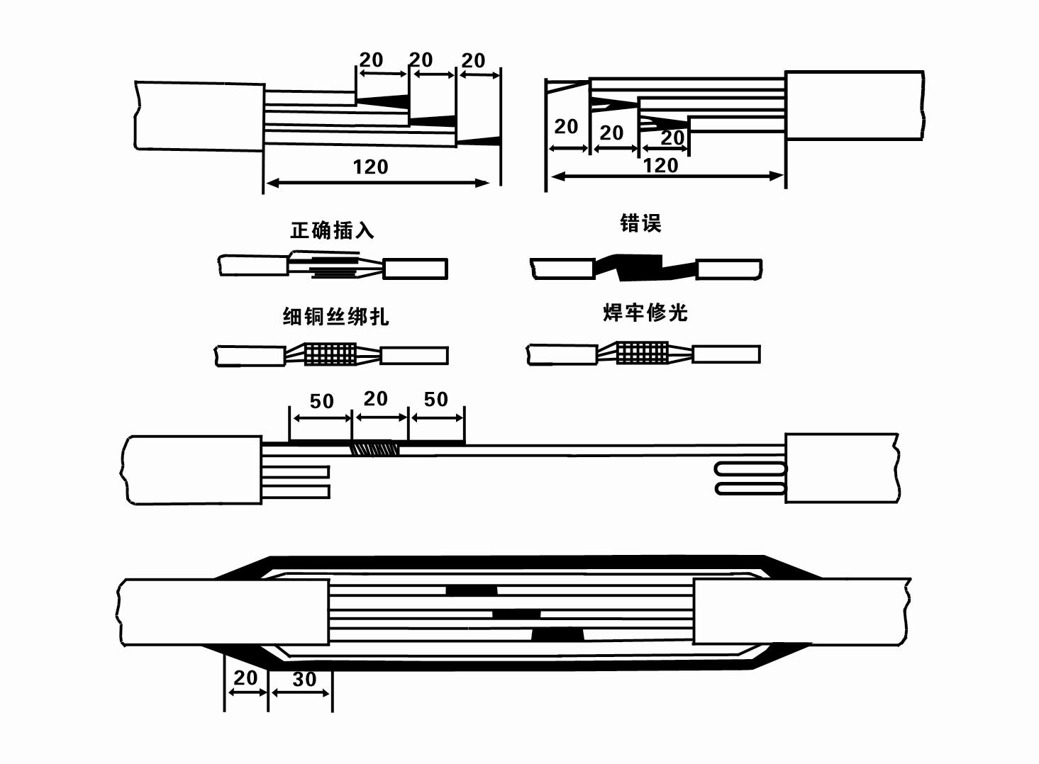
8. Notaðu margmæli til að athuga hvort þrífasa vírarnir séu tengdir og hvort DC viðnámið sé um það bil jafnvægi.
9. Athugaðu hvort rafrásin og spennigetan sé ofhlaðin og tengdu síðan yfirálagsvarnarrofann eða ræsibúnaðinn. Sjá töflu 2 fyrir tilteknar gerðir og Helltu síðan fötu af vatni í vatnsdæluna frá vatnsdæluúttakinu til að smyrja gúmmílögin í dælunni og settu svo rafdælu á kafi upprétta og stöðuga. Ræstu (ekki meira en eina sekúndu) og athugaðu hvort stýrisstefnan sé í samræmi við stýrismerkið. Ef ekki skaltu skipta um hvaða tengi sem er á þriggja fasa kapalnum. Settu síðan síuna upp og búðu þig undir að fara niður brunninn. Ef hún er notuð við sérstök tækifæri (svo sem skurði, skurði, ám, tjarnir, tjarnir o.s.frv.), verður rafdælan að vera jarðtengd á áreiðanlegan hátt.
(2) Uppsetningarbúnaður og verkfæri:
1. Eitt par af lyftikeðjum fyrir meira en tvö tonn.
2. Þrífótur með lóðrétta hæð sem er ekki minna en fjórir metrar.
3. Tvö hengireipi (vírareipi) sem geta borið meira en eitt tonn (geta borið þyngd heils vatnsdælusetts).
4. Settu upp tvö pör af klemmum (spelkum).
5. Skiplyklar, hamar, skrúfjárn, rafmagnsverkfæri og tæki o.fl.
(3) Uppsetning rafdælu:
1. Uppsetningarskýringarmynd rafdælunnar er sýnd á mynd 2. Sérstakar uppsetningarstærðir eru sýndar í töflu 3 "Listi yfir uppsetningarstærðir djúpdælunnar".
2. Rafdrifnar dælur sem eru undir 30 metrum að hæð má hífa beint í brunninn með því að nota slöngur og víra eða aðra hampi reipi sem geta borið alla þyngd vélarinnar, vatnsleiðslur og vatns í pípunum.
3. Dælur með yfir 30 metra hæð nota stálrör og uppsetningarröðin er sem hér segir:
①Notaðu klemmu til að klemma efri enda vatnsdælunnar (mótorinn og vatnsdælan hafa verið tengd á þessum tíma), lyftu honum með hangandi keðju og bindðu það hægt í brunninn þar til Settu klemmuna á brunnhausinn og fjarlægðu hangandi keðja.
② Notaðu annað par af klemmum til að klemma rör, lyftu því með hangandi keðju í 15 cm fjarlægð frá flansinum og lækkaðu það hægt. Milli rörflans og dæluflans Settu gúmmípúðann á sinn stað og hertu rörið og dældu jafnt með boltum, rærum og gormaskífum.
③ Lyftu djúpdælunni örlítið, fjarlægðu klemmuna á efri enda vatnsdælunnar, bindðu snúruna þétt við vatnsrörið með plastbandi og festu hana hægt niður þar til klemman er sett við brunnhausinn.
④Notaðu sömu aðferð til að binda allar vatnsleiðslur í brunninn.
⑤Eftir að úttakssnúran er tengd við stjórnrofann er hún tengd við þriggja fasa aflgjafann.
(4) Atriði sem þarf að hafa í huga við uppsetningu:
1. Ef truflun finnst meðan á dæluferlinu stendur, snúðu eða dragðu vatnspípuna til að sigrast á stöðvunarpunktinum. Ef ýmsar ráðstafanir virka enn ekki, vinsamlegast Ekki þvinga dæluna niður til að forðast skemmdir á rafdælunni og holunni.
2. Við uppsetningu skal setja gúmmípúða við flans hvers rörs og herða jafnt.
3. Þegar vatnsdælan er lækkuð niður í brunninn ætti að setja hana í miðja brunnspípuna til að koma í veg fyrir að dælan gangi á móti brunnveggnum í langan tíma, sem veldur því að dælan titrar og mótorinn sópar og brennir. .
4. Ákvarðu dýpt vatnsdælunnar í botn holunnar í samræmi við rennandi sand- og siltskilyrði holunnar. Ekki grafa dæluna í leðjuna. Fjarlægðin frá vatnsdælunni að botni holunnar er að jafnaði ekki minni en 3 metrar (sjá mynd 2).
5. Vatnsinntaksdýpt vatnsdælunnar ætti að vera ekki minna en 1-1,5 metrar frá kraftmiklu vatnsborðinu að vatnsinntakshnútnum (sjá mynd 2). Annars geta legur vatnsdælunnar auðveldlega skemmst.
6. Lyfta vatnsdælunnar má ekki vera of lágt. Að öðrum kosti þarf að setja hliðarventil á brunnhausvatnsleiðsluna til að stjórna dæluflæðinu á nafnflæðispunkti til að koma í veg fyrir að mótorinn verði ofhlaðinn og brennur út vegna mikils rennslishraða.
7. Þegar vatnsdælan er í gangi, ætti vatnsframleiðslan að vera stöðug og jöfn, straumurinn ætti að vera stöðugur (við metnaðarvinnuskilyrði, yfirleitt ekki meira en 10% af nafnstraumnum), og það ætti ekki að vera titringur eða hávaði. Ef það er eitthvað óeðlilegt ætti að stöðva vélina til að komast að orsökinni og útrýma henni.
8. Þegar þú setur upp skaltu fylgjast með stillingu jarðtengingarvírs mótorsins (sjá mynd 2). Þegar vatnsrörið er stálpípa skaltu leiða það frá brunnhausklemmunni; þegar vatnsrörið er plastpípa skaltu leiða það frá jarðtengingarmerki rafdælunnar.
- 1.After installing the submersible pump, recheck the insulation resistance and three-phase continuity switch, check whether there is any error in the connection between the instrument and the starting equipment.If there is no problem, you can start to test the machine. After starting, observe whether the indication reading of each instrument is correct.If the rated voltage and current specified on the nameplate are exceeded, please observe whether the pump has noise or vibration.If everything is normal, it can be put into operation. After the pump runs for the first time for four hours, the motor thermal insulation resistance should be closed and tested quickly. Its value should not be less than 0.5 megaohm. After the pump stops, it should be restarted after five minutes to prevent the water column in the pipeline from completely reversing, which will cause the motor to burn out due to excessive current.
- 2.After the pump is put into normal operation, in order to prolong its service life, it is necessary to check whether the supply voltage, working current and insulation resistance are normal regularly. If the following conditions are found, the machine should be stopped immediately to troubleshoot.
- 1.Under the rated working condition, the current exceeds 20%.
- 2.The dynamic water level drops to the water inlet section, resulting in intermittent water.
- 3.The submersible pump has severe vibration or noise.
- 4.The supply voltage is lower than 340 volts.
- 5.A fuse is burned out.
- 6.The water pipeline is damaged.
- 7.The motor's insulation resistance to the geothermal state is lower than 0.5 megaohm.
- 3.Unit disassembly:
- - Losaðu kapalbandið, fjarlægðu leiðsluhlutann og fjarlægðu vírplötuna.
- - screw down the water bolt, put out the water in the motor chamber.
- - fjarlægðu síuna, losaðu fastu skrúfuna á tenginu til að festa mótorskaftið.
- 4.screw down the bolt connecting the water inlet section with the motor, and separate the pump from the motor (pay attention to the unit cushion when separating, to prevent the bending of the pump shaft)
- 5.the disassembly sequence of the pump is: (see figure 1) water inlet section, impeller, diversion shell, impeller...... check valve body, when removing the impeller, use special tools to loosen the conical sleeve of the fixed impeller first, and avoid bending and bruising the pump shaft in the process of disassembly.
- 6.the disassembly process of the motor is: (see figure 1) place the motor on the platform, and remove the nuts, base, shaft head locking nut, thrust plate, key, lower guide bearing seat and double head bolt from the bottom of the motor in turn, and then take out the rotor (pay attention not to damage the wire package) and finally remove the connecting section and upper guide bearing seat.
- 7.unit assembly: before assembly, the rust and dirt of the parts should be cleaned, and the mating surface and fasteners coated with sealant, and then assembled in the opposite order of disassembly (the motor shaft moves up and down after assembly for about one millimeter), after assembly, the coupling should be flexible, and then the filter screen test machine. Submersible pumps shall be taken out of the well for dismantling and maintenance according to Article 5 after a year of operation, or less than a year of operation but two years of diving time, and the worn parts shall be replaced.
1, settu vatnið í mótorholið (sérstaklega á veturna til að koma í veg fyrir að mótorinn frjósi) og bindðu snúruna vel.
2, store in an indoor room without corrosive substances and gases, with a temperature below 40 °C.
3, langtíma notkun ætti að borga eftirtekt til ryðvarnar á kafdælum.
- Hjólhjól
- Skafthylki
- Skafthylsa úr gúmmíi
-
Þéttihringur
01 Vatnsinntak djúpbrunns
02 Vatnsveita í háhýsum
03 fjallavatnsveita
04 turn vatn
05 Landbúnaðaráveita
06 garðáveita
07 vatnsinntaka ánna
08 heimilisvatn


