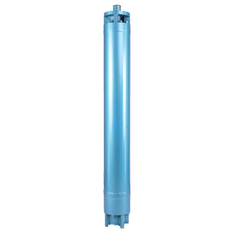
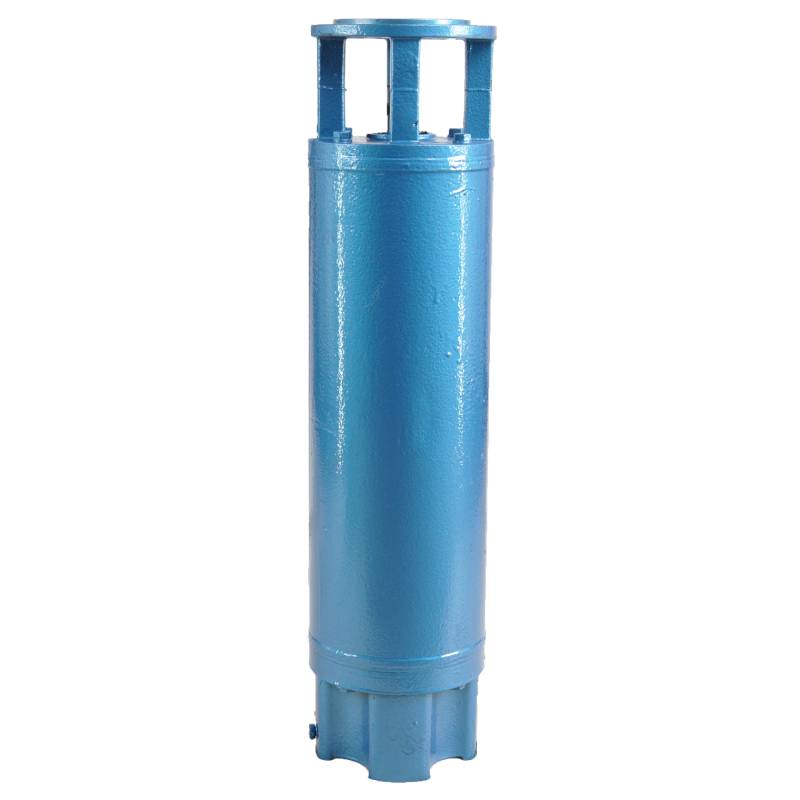
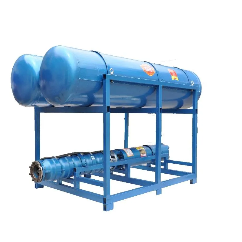
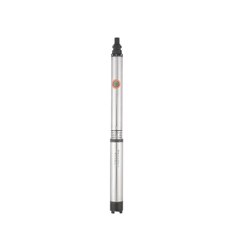
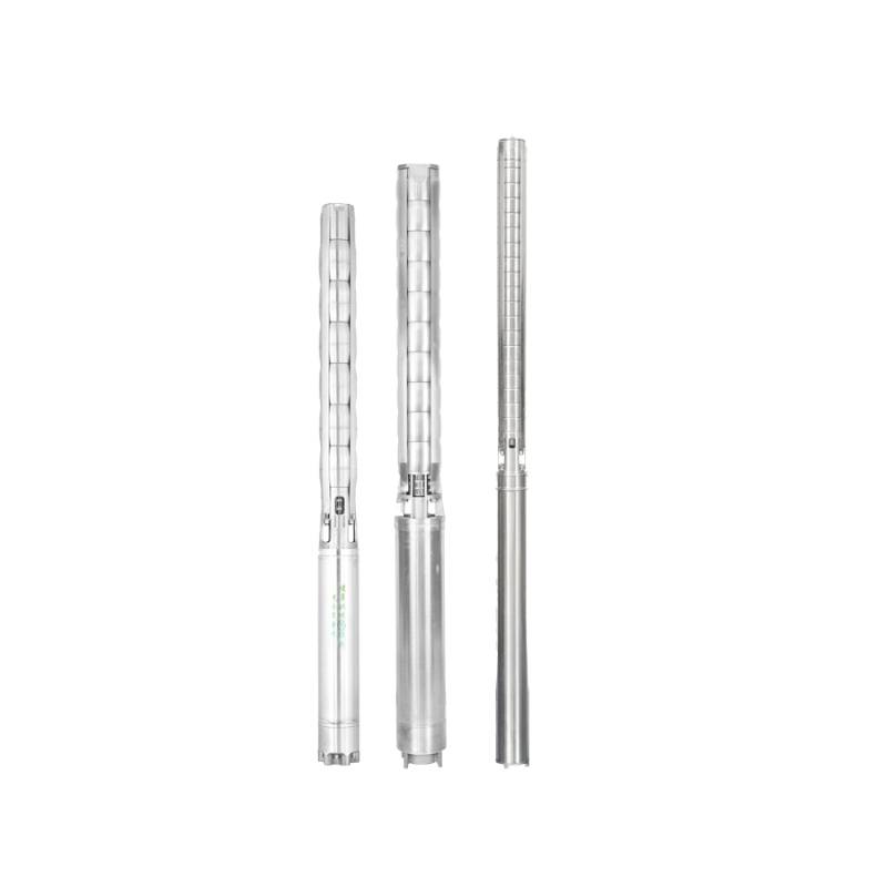
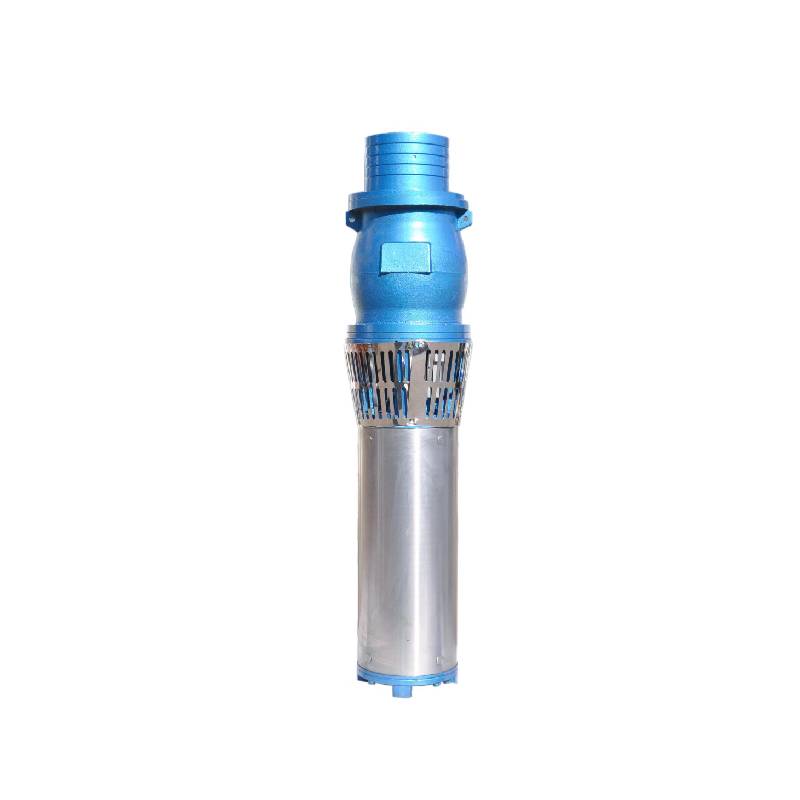
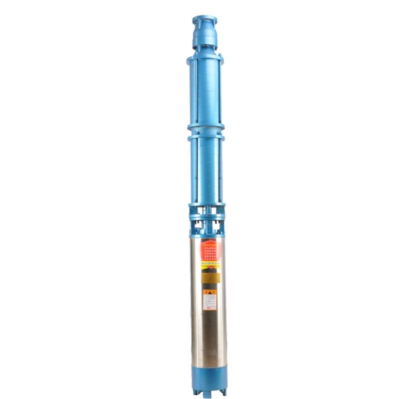
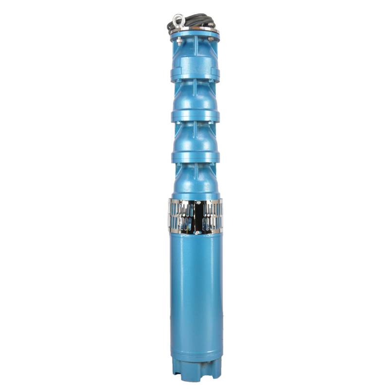
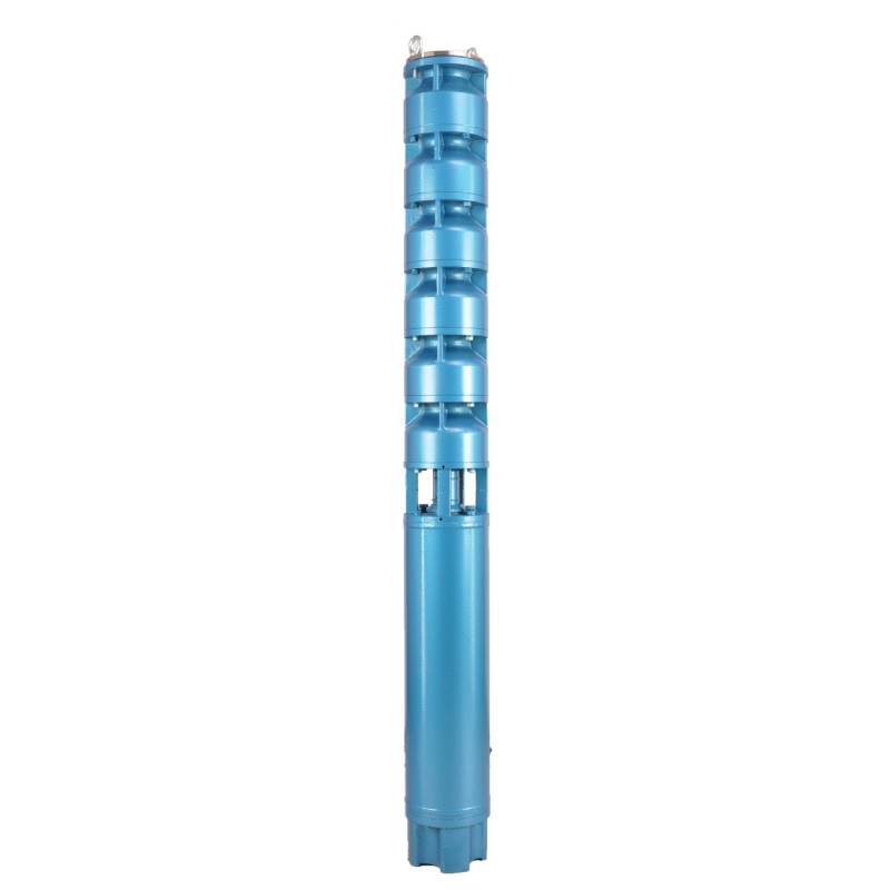
The product adopts special water-resistant wire for motor winding, with excellent characteristics such as high frequency shock resistance, pulse peak voltage shock resistance and high temperature aging resistance. The frequency conversion winding design ensures the motor to operate smoothly between 1Hz and 50Hz for a long time, making the frequency conversion deep well pump more energy saving and longer service life.
We are honored to introduce our products, this product provides three-phase AC 380V power supply (tolerance of ± 5%), 50HZ voltage (tolerance of ± 1%). At the same time, our products require strict water quality requirements: water temperature is not higher than 20 °C; solid impurities content (mass ratio) is not greater than 0.01%; PH value (pH) is 6.5-8.5; hydrogen sulfide content is not greater than 1.5mg/L; chloride ion content is not greater than 400mg/L. The motor adopts closed or water-filled wet structure, which must be filled with clean water before use to prevent empty. Tighten the water charging and deflating bolts before use, otherwise, it is not allowed to use. The submersible pump must be completely immersed in water to work, the immersion depth shall not exceed 70 meters, and the distance between the bottom of the submersible pump and the bottom of the well shall not be less than 3 meters. The well water flow shall meet the output and continuous operation requirements of the submersible pump, and the output of the submersible pump shall be controlled at 0.7-1.2 times of the rated flow. The well must be vertical, and the submersible pump can not be used horizontally or inverted, but only vertically. The submersible pump must be equipped with cables according to requirements, and is equipped with external overload protection devices. It is strictly prohibited to conduct no-load tests on the pump without water. Our products guarantee to provide you with high quality and stable performance, while meeting your needs to ensure safe and reliable.
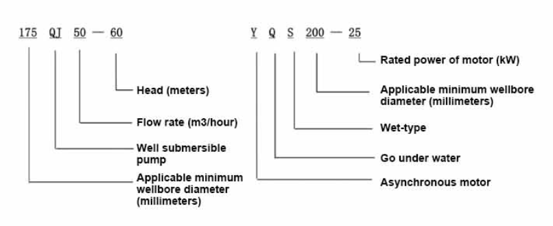
| Modell | Durchfluss (m3/h) | Kopf (M) |
Drehgeschwindigkeit (Wechselpunkt) |
Wasserpumpe(%) | Auslauf Durchmesser (mm) |
Gut anwendbar Durchmesser (mm) |
Bewertet power(KW) |
Bewertet Spannung (V) |
Bewertet Strom (A) |
Motoreffizienz (%) | power factorcosφ | Einheit Radiale Maximalgröße (mm) |
|||||||||
| 175QJ10-42 | 10 | 42 | 2850 | 53 | 50 | 175über | 3 | 380 | 7.8 | 74.0 | 0.79 | 168 | |||||||||
| 175QJ10-56 | 56 | 4 | 10.1 | 76.0 | 0.79 | ||||||||||||||||
| 175QJ10-70 | 70 | 4 | 10.1 | 76.0 | 0.79 | ||||||||||||||||
| 175QJ10-84 | 84 | 5.5 | 13.6 | 77.0 | 0.8 | ||||||||||||||||
| 175QJ10-112 | 112 | 7.5 | 18.4 | 77.5 | 0.8 | ||||||||||||||||
| 175QJ10-126 | 126 | 7.5 | 18.4 | 77.5 | 0.8 | ||||||||||||||||
| 175QJ10-140 | 140 | 9.2 | 22.1 | 78.0 | 0.81 | ||||||||||||||||
| 175QJ15-42 | 15 | 42 | 2850 | 58 | 50 | 175über | 4 | 380 | 10.1 | 76.0 | 0.79 | 168 | |||||||||
| 175QJ15-55 | 55 | 5.5 | 13.6 | 77.0 | 0.8 | ||||||||||||||||
| 175QJ15-65 | 65 | 5.5 | 13.6 | 77.0 | 0.8 | ||||||||||||||||
| 175QJ15-85 | 85 | 7.5 | 18.4 | 77.5 | 0.8 | ||||||||||||||||
| 175QJ15-112 | 112 | 9.2 | 22.1 | 78.0 | 0.81 | ||||||||||||||||
| 175QJ20-26 | 20 | 26 | 2850 | 64 | 50 | 175über | 3 | 380 | 7.8 | 74.0 | 0.79 | 168 | |||||||||
| 175QJ20-39 | 39 | 4 | 10.1 | 76.0 | 0.79 | ||||||||||||||||
| 175QJ20-52 | 52 | 5.5 | 13.6 | 77.0 | 0.8 | ||||||||||||||||
| 175QJ20-78 | 78 | 7.5 | 18.4 | 77.5 | 0.8 | ||||||||||||||||
| 175QJ20-91 | 91 | 9.2 | 22.1 | 78.0 | 0.81 | ||||||||||||||||
| 175QJ20-104 | 104 | 11 | 26.1 | 79.0 | 0.81 | ||||||||||||||||
| 175QJ20-130 | 130 | 13 | 30.1 | 80.0 | 0.82 | ||||||||||||||||
| 175QJ20-156 | 156 | 15 | 34.7 | 80.0 | 0.82 | ||||||||||||||||
| 175QJ20-182 | 187 | 18.5 | 42.6 | 80.5 | 0.82 | ||||||||||||||||
| 175QJ20-208 | 208 | 22 | 49.7 | 81.0 | 0.83 | ||||||||||||||||
| 175QJ20-247 | 247 | 25 | 56.5 | 81.0 | 0.83 | ||||||||||||||||
| 175QJ20-273 | 273 | 30 | 66.6 | 81.5 | 0.84 | ||||||||||||||||
| 175QJ20-299 | 299 | 30 | 66.6 | 81.5 | 0.84 | ||||||||||||||||
| 175QJ20-325 | 325 | 32 | 71.0 | 81.5 | 0.84 | ||||||||||||||||
| 175QJ20-364 | 364 | 37 | 82.1 | 81.5 | 0.84 | ||||||||||||||||
| 175QJ25-26 | 25 | 26 | 2850 | 66 | 65 | 175über | 3 | 380 | 7.8 | 74.0 | 0.79 | 168 | |||||||||
| 175QJ25-39 | 39 | 5.5 | 13.6 | 77.0 | 0.8 | ||||||||||||||||
| 175QJ25-65 | 25 | 65 | 2850 | 66 | 65 | 175über | 7.5 | 380 | 18.4 | 77.5 | 0.8 | 168 | |||||||||
| 175QJ25-78 | 78 | 9.2 | 22.1 | 78.0 | 0.81 | ||||||||||||||||
| 175QJ25-91 | 91 | 11 | 26.1 | 79.0 | 0.81 | ||||||||||||||||
| 175QJ25-104 | 104 | 13 | 30.1 | 80.0 | 0.82 | ||||||||||||||||
| 175QJ25-130 | 130 | 15 | 34.7 | 80.0 | 0.82 | ||||||||||||||||
| 175QJ25-156 | 156 | 18.5 | 42.6 | 80.5 | 0.82 | ||||||||||||||||
| 175QJ25-182 | 182 | 22 | 49.7 | 81.0 | 0.83 | ||||||||||||||||
| 175QJ25-208 | 208 | 25 | 56.5 | 81.0 | 0.83 | ||||||||||||||||
| 175QJ25-221 | 221 | 30 | 66.6 | 81.5 | 0.84 | ||||||||||||||||
| 175QJ25-247 | 247 | 30 | 66.6 | 81.5 | 0.84 | ||||||||||||||||
| 175QJ25-260 | 260 | 32 | 71.0 | 81.5 | 0.84 | ||||||||||||||||
| 175QJ25-299 | 299 | 37 | 82.1 | 81.5 | 0.84 | ||||||||||||||||
| 175QJ30-30 | 30 | 30 | 2850 | 67 | 80 | 175über | 4 | 380 | 10.1 | 76.0 | 0.79 | 168 | |||||||||
| 175QJ30-40 | 40 | 5.5 | 13.6 | 77.0 | 0.8 | ||||||||||||||||
| 175QJ32-24 | 32 | 24 | 2850 | 67 | 80 | 175über | 4 | 380 | 10.1 | 76.0 | 0.79 | 168 | |||||||||
| 175QJ32-36 | 36 | 5.5 | 13.6 | 77.0 | 0.8 | ||||||||||||||||
| 175QJ32-48 | 48 | 7.5 | 18.4 | 77.5 | 0.8 | ||||||||||||||||
| 175QJ32-60 | 60 | 9.2 | 22.1 | 78.0 | 0.81 | ||||||||||||||||
| 175QJ32-72 | 72 | 11 | 26.1 | 79.0 | 0.81 | ||||||||||||||||
| 175QJ32-84 | 84 | 13 | 30.1 | 80.0 | 0.82 | ||||||||||||||||
| 175QJ32-96 | 96 | 15 | 34.7 | 80.0 | 0.82 | ||||||||||||||||
| 175QJ32-120 | 120 | 18.5 | 42.6 | 80.5 | 0.82 | ||||||||||||||||
| 175QJ32-144 | 144 | 22 | 49.7 | 81.0 | 0.83 | ||||||||||||||||
| 175QJ32-168 | 168 | 25 | 56.5 | 81.0 | 0.83 | ||||||||||||||||
| 175QJ32-180 | 180 | 30 | 66.6 | 81.5 | 0.84 | ||||||||||||||||
| 175QJ32-192 | 192 | 30 | 66.6 | 81.5 | 0.84 | ||||||||||||||||
| 175QJ32-204 | 204 | 32 | 71.0 | 81.5 | 0.84 | ||||||||||||||||
| 175QJ32-240 | 240 | 37 | 82.1 | 81.5 | 0.84 | ||||||||||||||||
| 175QJ35-60 | 35 | 60 | 2850 | 67 | 80 | 175über | 10 | 380 | 25.0 | 78.0 | 0.78 | 168 | |||||||||
| 175QJ35-75 | 75 | 13 | 30.1 | 80.0 | 0.82 | ||||||||||||||||
| 175QJ35-100 | 100 | 17 | 40.9 | 80.0 | 0.79 | ||||||||||||||||
| 175QJ40-24 | 40 | 24 | 2850 | 70 | 80 | 175über | 5.5 | 380 | 13.6 | 77.0 | 0.8 | 168 | |||||||||
| 175QJ40-30 | 30 | 5.5 | 13.6 | 77.0 | 0.8 | ||||||||||||||||
| 175QJ40-36 | 36 | 7.5 | 18.4 | 77.5 | 0.8 | ||||||||||||||||
| 175QJ40-48 | 48 | 9.2 | 22.1 | 78.0 | 0.81 | ||||||||||||||||
| 175QJ40-60 | 60 | 11 | 26.1 | 79.0 | 0.81 | ||||||||||||||||
| 175QJ40-72 | 72 | 13 | 30.1 | 80.0 | 0.82 | ||||||||||||||||
| 175QJ40-84 | 84 | 15 | 34.7 | 80.0 | 0.82 | ||||||||||||||||
| 175QJ40-96 | 96 | 18.5 | 42.6 | 80.5 | 0.82 | ||||||||||||||||
| 175QJ40-120 | 120 | 22 | 49.7 | 81.0 | 0.83 | ||||||||||||||||
| 175QJ40-132 | 132 | 25 | 56.5 | 81.0 | 0.83 | ||||||||||||||||
| 175QJ40-144 | 144 | 30 | 66.6 | 81.5 | 0.84 | ||||||||||||||||
| 175QJ40-156 | 156 | 30 | 66.6 | 81.5 | 0.84 | ||||||||||||||||
| 175QJ40-168 | 168 | 32 | 71.0 | 81.5 | 0.84 | ||||||||||||||||
| 175QJ40-192 | 192 | 37 | 82.1 | 81.5 | 0.84 | ||||||||||||||||
| 175QJ50-24 | 50 | 24 | 2850 | 72 | 80 | 175über | 5.5 | 380 | 13.6 | 77.0 | 0.8 | 168 | |||||||||
| 175QJ50-36 | 36 | 9.2 | 22.1 | 78.0 | 0.81 | ||||||||||||||||
| 175QJ50-48 | 48 | 11 | 26.1 | 79.0 | 0.81 | ||||||||||||||||
| 175QJ50-60 | 60 | 13 | 30.1 | 80.0 | 0.82 | ||||||||||||||||
| 175QJ50-70 | 70 | 17 | 40.9 | 80.0 | 0.79 | ||||||||||||||||
| 175QJ50-84 | 84 | 18.5 | 42.6 | 80.5 | 0.82 | ||||||||||||||||
| 175QJ50-96 | 96 | 22 | 49.7 | 81.0 | 0.83 | ||||||||||||||||
| 175QJ50-108 | 108 | 25 | 56.5 | 81.0 | 0.83 | ||||||||||||||||
| 175QJ50-120 | 120 | 30 | 66.6 | 81.5 | 0.84 | ||||||||||||||||
| 175QJ50-132 | 132 | 30 | 66.6 | 81.5 | 0.84 | ||||||||||||||||
| 175QJ50-144 | 144 | 32 | 71.0 | 81.5 | 0.84 | ||||||||||||||||
| 175QJ50-156 | 156 | 37 | 82.1 | 81.5 | 0.84 | ||||||||||||||||
| 175QJ63-22 | 63 | 22 | 2850 | 72 | 80 | 175über | 7.5 | 380 | 18.4 | 77.5 | 0.8 | 168 | |||||||||
| 175QJ63-44 | 44 | 13 | 30.1 | 80.0 | 0.82 | ||||||||||||||||
| 175QJ63-55 | 55 | 15 | 34.7 | 80.0 | 0.82 | ||||||||||||||||
| 175QJ63-66 | 66 | 18.5 | 42.6 | 80.5 | 0.82 | ||||||||||||||||
| 175QJ63-77 | 77 | 22 | 49.7 | 81.0 | 0.83 | ||||||||||||||||
| 175QJ63-88 | 88 | 25 | 56.5 | 81.0 | 0.83 | ||||||||||||||||
| 175QJ63-99 | 63 | 99 | 2850 | 72 | 80 | 175über | 30 | 380 | 66.6 | 81.5 | 0.84 | 168 | |||||||||
| 175QJ63-110 | 110 | 32 | 71.0 | 81.5 | 0.84 | ||||||||||||||||
| 175QJ63-132 | 132 | 37 | 82.1 | 81.5 | 0.84 | ||||||||||||||||
| 175QJ80-9 | 80 | 9 | 2850 | 73 | 100 | 175über | 4 | 380 | 10.1 | 76.0 | 0.79 | 168 | |||||||||
| 175QJ80-18 | 18 | 7.5 | 18.4 | 77.5 | 0.8 | ||||||||||||||||
| 175QJ80-27 | 27 | 11 | 26.1 | 79.0 | 0.81 | ||||||||||||||||
| 175QJ80-36 | 36 | 15 | 34.7 | 80.0 | 0.82 | ||||||||||||||||
| 175QJ80-45 | 45 | 18.5 | 42.6 | 80.5 | 0.82 | ||||||||||||||||
| 175QJ80-54 | 54 | 22 | 49.7 | 81.0 | 0.83 | ||||||||||||||||
| 175QJ80-63 | 63 | 25 | 56.5 | 81.0 | 0.83 | ||||||||||||||||
| 175QJ80-72 | 72 | 25 | 56.5 | 81.0 | 0.83 | ||||||||||||||||
| 175QJ80-81 | 81 | 30 | 66.6 | 81.5 | 0.84 | ||||||||||||||||
| 175QJ80-90 | 90 | 32 | 71.0 | 81.5 | 0.84 | ||||||||||||||||
| 175QJ80-98 | 98 | 37 | 82.1 | 81.5 | 0.84 | ||||||||||||||||
This well submersible pump is a pump suitable for clean water. Digging new wells and pumping sediment and turbid water are strictly prohibited. The voltage grade of the well pump is 380V/50HZ. Submersible motors with other voltage grades need to be customized. Underground cables must use waterproof cables and must be equipped with starting equipment, such as distribution boxes, etc. The starting equipment should have common comprehensive motor protection functions, such as overload short circuit protection, phase loss protection, undervoltage protection, grounding protection and idling protection, etc. In abnormal cases, the protection device should be tripped in time. During installation and use, the pump must be reliably grounded. It is prohibited to push and pull the switch when hands and feet are wet. The power supply must be cut off before installation and maintenance of the pump. The place where the pump is used must be set up with obvious "anti-electric shock" marks. Before going down the well or installation, the motor must be injected with distilled water or non-corrosive clear cold water in the inner cavity, and the intake/drain bolts must be tightened. When testing the pump on the ground, water must be injected into the pump chamber to lubricate the rubber bearings. The instant start time should not exceed one second to check whether the direction is correct. The same as the steering instructions. Pay attention to safety when the pump is upright to prevent tilting and injury. Strictly in accordance with the provisions of the pump lift and flow range, to prevent the pump flow at low lift or in high lift pull too large, resulting in extreme wear of thrust bearings and other components, the motor due to overload and burn. After put into the well, the measurement of the motor and the ground insulation resistance value, not less than 100M. After the start, regular observation of voltage and current, and check the motor winding insulation is in line with the requirements of the provisions. If the temperature of the storage site is below the freezing point, the water in the pump chamber should be drained to prevent the water in the motor chamber from freezing and damaging the motor due to low temperature.
Kurze Einführung in die Struktur: Der Pumpenteil besteht hauptsächlich aus Pumpenwelle, Laufrad, Umleitungsgehäuse, Gummilager, Rückschlagventilkörper (optionale Teile) und anderen Komponenten. Der Motorteil besteht hauptsächlich aus Basis, Druckregulierungsfolie, Axiallager, Axialplatte, unterem Führungslagersitz, Stator, Rotor, oberem Führungslagersitz, Sandring, Wassereinlassabschnitt, Kabel und anderen Komponenten.
Zu den Hauptmerkmalen des Produkts gehören:
1.The motor is a water-filled wet submersible three-phase asynchronous motor, the motor cavity is full of clean water, used to cool the motor and lubricate the bearing, the pressure regulating film at the bottom of the motor is used to adjust the expansion and contraction pressure difference of the water inside the body caused by the change of the temperature rise of the motor.
2.In order to prevent the sand in the well water from entering the motor, the upper end of the motor shaft is equipped with two oil seals, and a sand ring is installed to form a sand prevention structure.
3.In order to prevent the pump shaft from running up when starting, the pump shaft and the motor shaft are connected by a coupling, and an upper thrust bearing is installed at the lower part of the motor.
4.The lubrication of the motor and the pump bearing is water lubrication.
5.The motor stator winding is made of high quality submersible motor winding wire, with high insulation performance.
6.The pump is designed by computer CAD, with simple structure and good technical performance.

(1)Vorbereitung vor der Installation:
1. Prüfen Sie, ob die Tauchpumpe die in der Anleitung angegebenen Einsatzbedingungen und den Einsatzbereich erfüllt.
2. Messen Sie mit einem schweren Gegenstand, dessen Durchmesser dem maximalen Außendurchmesser der Tauchpumpe entspricht, ob der Innendurchmesser des Bohrlochs für die Tauchpumpe geeignet ist, und messen Sie, ob die Bohrlochtiefe den Installationsanforderungen entspricht.
3. Überprüfen Sie, ob das Bohrloch sauber ist und ob das Brunnenwasser trübe ist. Verwenden Sie niemals eine Tauchpumpe, um Schlamm und Sandwasser aus der Brunnenpumpe zu waschen, um vorzeitige Schäden an der Tauchpumpe zu vermeiden.
4. Prüfen Sie, ob die Position der Schweißkopf-Montageklemme geeignet ist und ob sie der Qualität der gesamten Einheit standhält
5. Überprüfen Sie, ob die Komponenten der Tauchpumpe vollständig sind und gemäß dem Montageplan im Handbuch ordnungsgemäß installiert wurden. Entfernen Sie das Filtersieb und drehen Sie die Kupplung, um zu sehen, ob sie sich flexibel dreht.
6. Die Wasserschraube abschrauben und den Motorhohlraum mit sauberem, nicht korrosivem Wasser füllen (Hinweis: unbedingt auffüllen), dann die Wasserschraube festziehen. Nach 12 Stunden Wassereinspritzung sollte der Isolationswiderstand des Motors bei Messung mit einem 500-V-Schütteltisch nicht weniger als 150 MQ betragen.
7. Cable joint, cut off a 120mm rubber sleeve from one end of the outgoing cable and the matching cable with an electrician's knifethen stagger the length of the three core wires in a stepped shape, peel off a 20mm copper core, scrape of the oxide layer on theoutside of the copper wire with a knife or sand cloth, and insert the two connected wire ends in palirs.After tying the layer tightly with fine copper wire, solder it thoroughly and firmly, and sand of any. burrs on the surface. Then, forthe three joints, use polyvester insulation tape to wrap them in a semi stacked manner for three lavers. Wrap the two ends of thewrapping layer tightywith nyion thread,and then use a semi stacked method to wrap the tape for three layers. Wrap the outellayer with high-pressure insulation tape for three layers. Finally, fold the threestrands together and repeatedly wrap them for fivelayers with high-pressure tape. Each layer must be tightly tied, and the interlayer joints must be tight and fimm to prevent water frompenetrating and damaging the insulation, After wrapping, soak in water at room temperature of 20 ’c for 12 hours, and measurethe insulation resistance with a shaking table, which should not be less than 100M Ω
Das beigefügte Diagramm zur Kabelverlegung sieht wie folgt aus: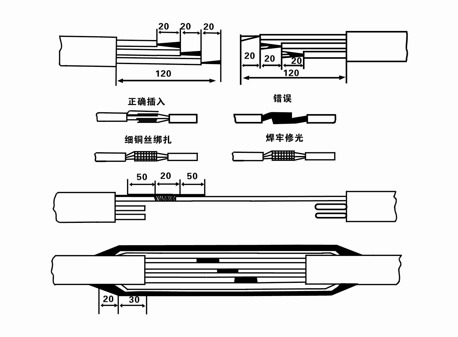
8. Prüfen Sie mit einem Multimeter, ob die Drehstromleitungen angeschlossen sind und der Gleichstromwiderstand etwa ausgeglichen ist.
9. Überprüfen Sie, ob der Stromkreis und die Transformatorkapazität überlastet sind, und schließen Sie dann den Überlastschutzschalter oder die Startvorrichtung an. Siehe Tabelle 2 für bestimmte Modelle. Gießen Sie dann einen Eimer Wasser aus dem Wasserpumpenauslass in die Wasserpumpe, um die Gummilager in der Pumpe zu schmieren, und stellen Sie die Tauchpumpe dann aufrecht und stabil auf. Starten Sie (nicht länger als eine Sekunde) und prüfen Sie, ob die Lenkrichtung mit dem Lenkzeichen übereinstimmt. Wenn nicht, tauschen Sie zwei beliebige Anschlüsse des Dreiphasenkabels aus. Installieren Sie dann den Filter und bereiten Sie sich darauf vor, in den Brunnen zu gehen. Bei Verwendung in besonderen Fällen (z. B. Gräben, Flüssen, Teichen, Teichen usw.) muss die Elektropumpe zuverlässig geerdet sein.
(2)Installationsausrüstung und Werkzeuge:
1. Ein Paar Hebeketten für mehr als zwei Tonnen.
2. Ein Stativ mit einer vertikalen Höhe von mindestens vier Metern.
3. Zwei Hängeseile (Drahtseile), die ein Gewicht von mehr als einer Tonne tragen können (können das Gewicht eines kompletten Wasserpumpensatzes tragen).
4. Installieren Sie zwei Paar Klammern (Schienen).
5. Schraubenschlüssel, Hämmer, Schraubendreher, elektrische Werkzeuge und Instrumente usw.
(3)Installation der elektrischen Pumpe:
1. Das Installationsdiagramm der Tauchelektropumpe ist in Abbildung 2 dargestellt. Die spezifischen Installationsabmessungen sind in Tabelle 3 „Liste der Installationsabmessungen der Tauchelektropumpe“ aufgeführt.
2. Tauchpumpen mit einer Förderhöhe von weniger als 30 Metern können mit Schläuchen und Drahtseilen oder anderen Hanfseilen, die das gesamte Gewicht der gesamten Maschine, der Wasserleitungen und des Wassers in den Rohren tragen können, direkt in den Brunnen gehoben werden.
3. Pumpen mit einer Förderhöhe von mehr als 30 Metern verwenden Stahlrohre und die Installationsreihenfolge ist wie folgt:
①Befestigen Sie das obere Ende des Wasserpumpenteils mit einer Klemme (Motor und Wasserpumpe sind zu diesem Zeitpunkt bereits verbunden), heben Sie es mit einer Hängekette an und binden Sie es langsam in den Brunnen, bis die Klemme auf den Brunnenkopf aufgesetzt und die Hängekette entfernt ist.
② Verwenden Sie ein weiteres Paar Klemmen, um ein Rohr festzuklemmen, heben Sie es mit einer Hängekette 15 cm vom Flansch entfernt an und senken Sie es langsam ab. Legen Sie zwischen Rohrflansch und Pumpenflansch das Gummipolster an und ziehen Sie Rohr und Pumpe mit Schrauben, Muttern und Federscheiben gleichmäßig fest.
③ Heben Sie die Tauchpumpe leicht an, entfernen Sie die Klemme am oberen Ende der Wasserpumpe, binden Sie das Kabel mit einem Kunststoffband fest an die Wasserleitung und binden Sie es langsam nach unten, bis die Klemme am Bohrlochkopf platziert ist.
④Verwenden Sie die gleiche Methode, um alle Wasserleitungen an den Brunnen anzuschließen.
⑤Nachdem das Ausgangskabel mit dem Steuerschalter verbunden ist, wird es an die dreiphasige Stromversorgung angeschlossen.
(4)Bei der Installation zu beachtende Punkte:
1. Wenn während des Pumpvorgangs ein Blockierungsphänomen festgestellt wird, drehen oder ziehen Sie am Wasserrohr, um die Blockierungsstelle zu beheben. Wenn verschiedene Maßnahmen immer noch nicht funktionieren, drücken Sie die Pumpe bitte nicht mit Gewalt nach unten, um Schäden an der Tauchpumpe und dem Brunnen zu vermeiden.
2. Während der Installation sollte am Flansch jedes Rohrs eine Gummiunterlage platziert und gleichmäßig festgezogen werden.
3. Wenn die Wasserpumpe in den Brunnen abgesenkt wird, sollte sie in der Mitte des Brunnenrohrs platziert werden, um zu verhindern, dass die Pumpe längere Zeit gegen die Brunnenwand läuft, was zu Vibrationen der Pumpe und zum Fegen und Verbrennen des Motors führen kann.
4. Bestimmen Sie die Tiefe der Wasserpumpe bis zum Boden des Brunnens entsprechend den fließenden Sand- und Schlickbedingungen des Brunnens. Vergraben Sie die Pumpe nicht im Schlamm. Der Abstand von der Wasserpumpe bis zum Boden des Brunnens beträgt im Allgemeinen nicht weniger als 3 Meter (siehe Abbildung 2).
5. Die Wassereintrittstiefe der Wasserpumpe sollte vom dynamischen Wasserstand bis zum Wassereinlassknoten nicht weniger als 1–1,5 Meter betragen (siehe Abbildung 2). Andernfalls können die Lager der Wasserpumpe leicht beschädigt werden.
6. Die Förderhöhe der Wasserpumpe darf nicht zu niedrig sein. Andernfalls muss an der Wasserleitung am Bohrlochkopf ein Absperrschieber installiert werden, um den Pumpendurchfluss am Nenndurchflusspunkt zu steuern und zu verhindern, dass der Motor aufgrund großer Durchflussraten überlastet wird und durchbrennt.
7. Wenn die Wasserpumpe läuft, sollte die Wasserabgabe kontinuierlich und gleichmäßig erfolgen, der Strom sollte stabil sein (unter Nennbetriebsbedingungen im Allgemeinen nicht mehr als 10 % des Nennstroms) und es sollten keine Vibrationen oder Geräusche auftreten. Bei Anomalien sollte die Maschine angehalten werden, um die Ursache herauszufinden und zu beseitigen.
8. Achten Sie bei der Installation auf die Einstellung des Motorerdungskabels (siehe Abbildung 2). Wenn es sich bei der Wasserleitung um ein Stahlrohr handelt, führen Sie es von der Bohrlochkopfklemme aus; wenn es sich bei der Wasserleitung um ein Kunststoffrohr handelt, führen Sie es von der Erdungsmarkierung der Elektropumpe aus.
- 1.After installing the submersible pump, recheck the insulation resistance and three-phase continuity switch, check whether there is any error in the connection between the instrument and the starting equipment.If there is no problem, you can start to test the machine. After starting, observe whether the indication reading of each instrument is correct.If the rated voltage and current specified on the nameplate are exceeded, please observe whether the pump has noise or vibration.If everything is normal, it can be put into operation. After the pump runs for the first time for four hours, the motor thermal insulation resistance should be closed and tested quickly. Its value should not be less than 0.5 megaohm. After the pump stops, it should be restarted after five minutes to prevent the water column in the pipeline from completely reversing, which will cause the motor to burn out due to excessive current.
- 2.After the pump is put into normal operation, in order to prolong its service life, it is necessary to check whether the supply voltage, working current and insulation resistance are normal regularly. If the following conditions are found, the machine should be stopped immediately to troubleshoot.
- 1.Under the rated working condition, the current exceeds 20%.
- 2.The dynamic water level drops to the water inlet section, resulting in intermittent water.
- 3.The submersible pump has severe vibration or noise.
- 4.The supply voltage is lower than 340 volts.
- 5.A fuse is burned out.
- 6.The water pipeline is damaged.
- 7.The motor's insulation resistance to the geothermal state is lower than 0.5 megaohm.
- 3.Unit disassembly:
- - Den Kabelbinder lösen, den Rohrleitungsteil herausnehmen und die Drahtplatte entfernen.
- - screw down the water bolt, put out the water in the motor chamber.
- - Filter entnehmen, Feststellschraube an der Kupplung lösen um die Motorwelle zu fixieren.
- 4.screw down the bolt connecting the water inlet section with the motor, and separate the pump from the motor (pay attention to the unit cushion when separating, to prevent the bending of the pump shaft)
- 5.the disassembly sequence of the pump is: (see figure 1) water inlet section, impeller, diversion shell, impeller...... check valve body, when removing the impeller, use special tools to loosen the conical sleeve of the fixed impeller first, and avoid bending and bruising the pump shaft in the process of disassembly.
- 6.the disassembly process of the motor is: (see figure 1) place the motor on the platform, and remove the nuts, base, shaft head locking nut, thrust plate, key, lower guide bearing seat and double head bolt from the bottom of the motor in turn, and then take out the rotor (pay attention not to damage the wire package) and finally remove the connecting section and upper guide bearing seat.
- 7.unit assembly: before assembly, the rust and dirt of the parts should be cleaned, and the mating surface and fasteners coated with sealant, and then assembled in the opposite order of disassembly (the motor shaft moves up and down after assembly for about one millimeter), after assembly, the coupling should be flexible, and then the filter screen test machine. Submersible pumps shall be taken out of the well for dismantling and maintenance according to Article 5 after a year of operation, or less than a year of operation but two years of diving time, and the worn parts shall be replaced.
1. Lassen Sie das Wasser im Motorraum ab (besonders im Winter, um ein Einfrieren des Motors zu verhindern) und binden Sie das Kabel gut fest.
2, store in an indoor room without corrosive substances and gases, with a temperature below 40 °C.
3. Bei längerem Gebrauch sollte auf den Rostschutz der Tauchpumpen geachtet werden.
- Laufrad
- Wellenschutzhülse
- Wellenschutzhülse aus Gummi
-
Siegelring
01 Wasserentnahme aus einem tiefen Brunnen
02 Hochwasserversorgung
03 Bergwasserversorgung
04 Turm Wasser
05 Landwirtschaftliche Bewässerung
06 Gartenbewässerung
07 Flusswasserentnahme
08 Brauchwasser


