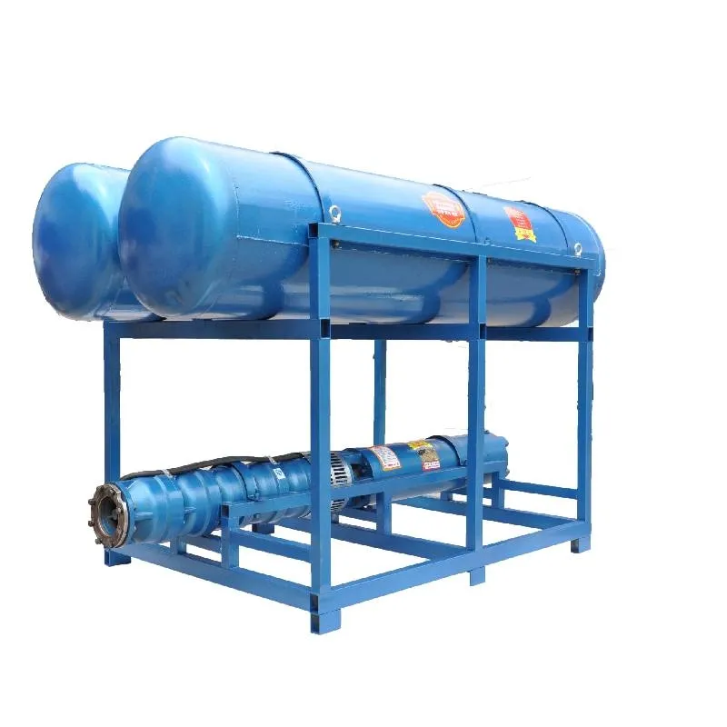
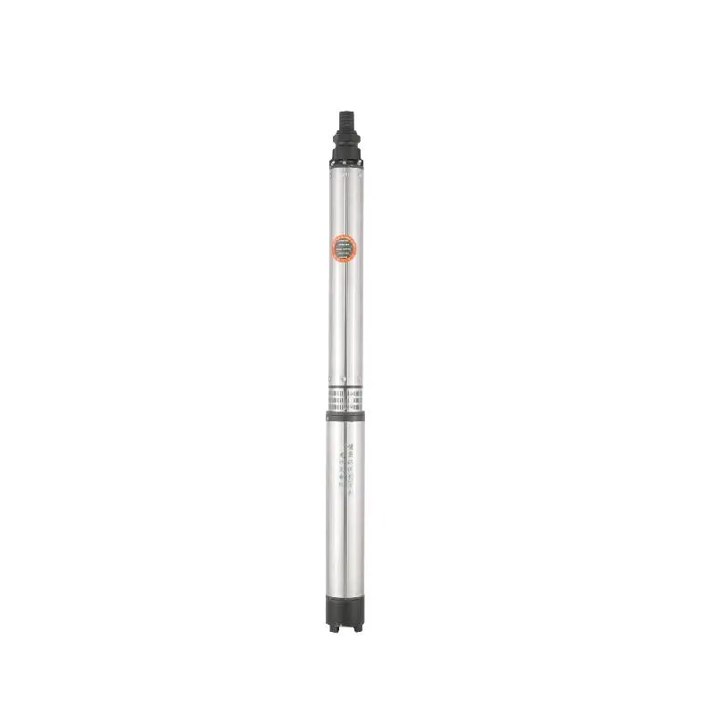
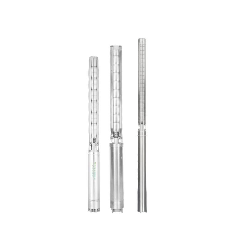
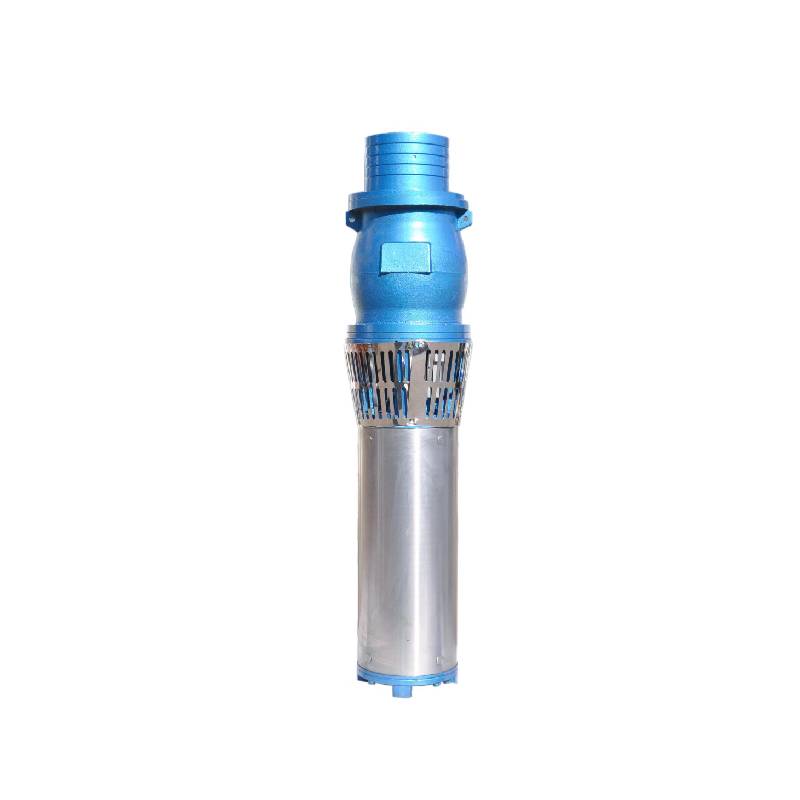
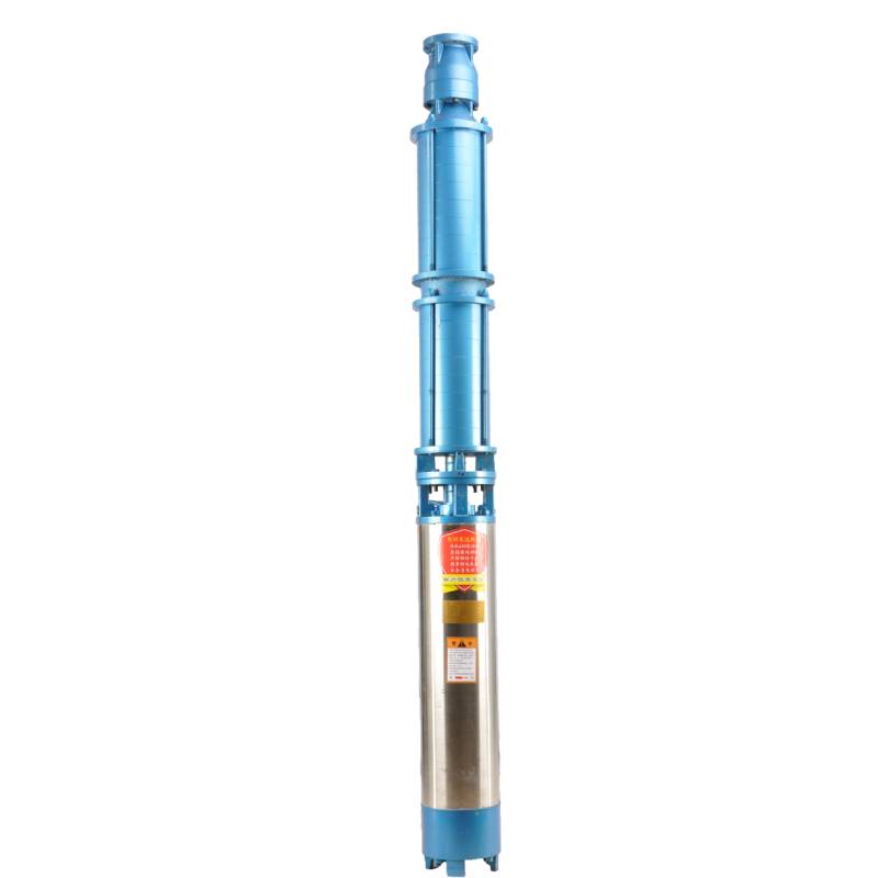
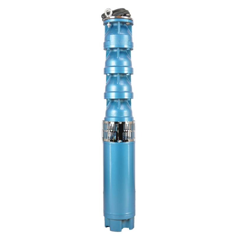
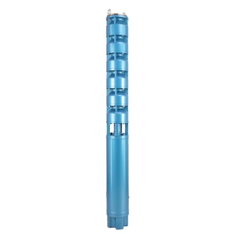
Frequency conversion winding design, ensure the motor in 1HZ-50HZ long-term stable conversion operation. Energy saving, longer service life.
1, alimentazione: trifase CA 380 V (tolleranza +/- 5%), 50 HZ (tolleranza +/- 1%).
2, qualità dell'acqua:
(1) water temperature is not higher than 20 °C;
(2) il contenuto di impurità solide (rapporto di massa) non è superiore allo 0,01%;
(3) Valore del pH (pH) 6,5-8,5;
(4) il contenuto di idrogeno solforato non è superiore a 1,5 mg/l;
(5) il contenuto di ioni cloruro non è superiore a 400 mg/l.
3, il motore è chiuso o ha una struttura bagnata piena d'acqua, prima dell'uso la cavità del motore sommergibile deve essere piena di acqua pulita, per evitare un falso pieno, quindi serrare l'iniezione d'acqua, i bulloni di rilascio dell'aria, altrimenti non è consentito l'uso
4, la pompa sommergibile deve essere completamente immersa nell'acqua, la profondità di immersione non è superiore a 70 m, il fondo della pompa sommergibile dal fondo del pozzo non è inferiore a 3 m.
5, il flusso dell'acqua del pozzo dovrebbe essere in grado di soddisfare la produzione dell'acqua della pompa sommergibile e il funzionamento continuo, la produzione dell'acqua della pompa sommergibile dovrebbe essere controllata a 0,7 - 1,2 volte la portata nominale.
6, il pozzo deve essere dritto, la pompa sommergibile non può essere utilizzata o scaricata, solo per uso verticale.
7, la pompa sommergibile deve essere abbinata al cavo secondo i requisiti e al dispositivo di protezione da sovraccarico esterno. 8, la pompa è severamente vietata senza la macchina per la prova a vuoto dell'acqua
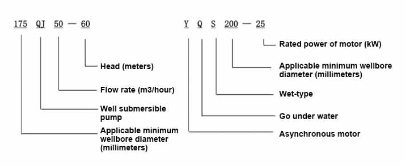
| Modello | Portata (m3/h) | Testa (M) |
Rotating speed(change/point) | Pompa dell'acqua(%) | Presa diametro (mm) |
Applicabile bene diametro (millimetro) |
Valutato potere (chilowatt) |
Rated voltage(V) | Ratedcurrent(A) | Efficienza motoria (%) | power factorcosφ | Unità Dimensione massima radiale (mm) |
Osservazione | |||||||||
| 125QJ5-34 | 5 | 34 | 2850 | 53 | 40 | 125Sopra | 1.5 | 380 | 4.23 | 70.0 | 0.77 | 118 | ||||||||||
| 125QJ5-51 | 51 | 2.2 | 6.03 | 72.0 | 0.77 | |||||||||||||||||
| 125QJ5-68 | 68 | 3 | 8.01 | 73.0 | 0.78 | |||||||||||||||||
| 125QJ5-85 | 85 | 4 | 10.53 | 74.0 | 0.78 | |||||||||||||||||
| 125QJ5-102 | 102 | 5.5 | 14.1 | 75.0 | 0.79 | |||||||||||||||||
| 125QJ5-119 | 119 | 5.5 | 14.1 | 75.0 | 0.79 | |||||||||||||||||
| 125QJ10-24 | 10 | 24 | 2850 | 60 | 50 | 125Sopra | 1.5 | 380 | 4.23 | 70.0 | 0.77 | 118 | ||||||||||
| 125QJ10-32 | 32 | 2.2 | 6.03 | 72.0 | 0.77 | |||||||||||||||||
| 125QJ10-48 | 48 | 3 | 8.01 | 73.0 | 0.78 | |||||||||||||||||
| 125QJ10-56 | 56 | 4 | 10.53 | 74.0 | 0.78 | |||||||||||||||||
| 125QJ10-72 | 72 | 5.5 | 14.1 | 75.0 | 0.79 | |||||||||||||||||
| 125QJ10-80 | 80 | 5.5 | 14.1 | 75.0 | 0.79 | |||||||||||||||||
| 125QJ10-104 | 104 | 7.5 | 19.0 | 76.0 | 0.79 | |||||||||||||||||
| 125QJ10-120 | 10 | 120 | 2850 | 60 | 50 | 125Sopra | 7.5 | 380 | 19.0 | 76.0 | 0.79 | 118 | ||||||||||
| 125QJ10-136 | 136 | 9.2 | 22.7 | 77.0 | 0.8 | |||||||||||||||||
| 125QJ15-36 | 15 | 36 | 2850 | 63 | 50 | 125Sopra | 2.2 | 380 | 6.03 | 72.0 | 0.77 | 118 | ||||||||||
| 125QJ15-39 | 39 | 3 | 8.01 | 73.0 | 0.78 | |||||||||||||||||
| 125QJ15-46 | 46 | 4 | 10.53 | 74.0 | 0.78 | |||||||||||||||||
| 125QJ15-52 | 52 | 4 | 10.53 | 74.0 | 0.78 | |||||||||||||||||
| 125QJ15-59 | 59 | 5.5 | 14.1 | 75.0 | 0.79 | |||||||||||||||||
| 125QJ15-65 | 65 | 5.5 | 14.1 | 75.0 | 0.79 | |||||||||||||||||
| 125QJ15-78 | 78 | 7.5 | 19.0 | 76.0 | 0.79 | |||||||||||||||||
| 125QJ15-91 | 91 | 7.5 | 19.0 | 76.0 | 0.79 | |||||||||||||||||
| 125QJ15-104 | 104 | 9.2 | 22.7 | 77.0 | 0.8 | |||||||||||||||||
| 125QJ20-16 | 20 | 16 | 2850 | 64 | 50 | 125Sopra | 2.2 | 380 | 6.03 | 72.0 | 0.77 | 118 | ||||||||||
| 125QJ20-24 | 24 | 3 | 8.01 | 73.0 | 0.78 | |||||||||||||||||
| 125QJ20-32 | 32 | 4 | 10.53 | 74.0 | 0.78 | |||||||||||||||||
| 125QJ20-40 | 40 | 4 | 10.53 | 74.0 | 0.78 | |||||||||||||||||
| 125QJ20-48 | 48 | 5.5 | 14.1 | 75.0 | 0.79 | |||||||||||||||||
| 125QJ20-56 | 56 | 5.5 | 14.1 | 75.0 | 0.79 | |||||||||||||||||
| 125QJ20-64 | 64 | 7.5 | 19.0 | 76.0 | 0.79 | |||||||||||||||||
| 125QJ20-72 | 72 | 7.5 | 19.0 | 76.0 | 0.79 | |||||||||||||||||
| 125QJ20-80 | 80 | 9.2 | 22.7 | 77.0 | 0.8 | |||||||||||||||||
| 125QJ25-12 | 25 | 12 | 2850 | 64 | 65 | 125Sopra | 2.2 | 380 | 6.03 | 72.0 | 0.77 | 118 | ||||||||||
| 125QJ25-18 | 18 | 3 | 8.01 | 73.0 | 0.78 | |||||||||||||||||
| 125QJ25-24 | 24 | 4 | 10.53 | 74.0 | 0.78 | |||||||||||||||||
| 125QJ25-30 | 30 | 4 | 10.53 | 74.0 | 0.78 | |||||||||||||||||
| 125QJ25-36 | 36 | 5.5 | 14.1 | 75.0 | 0.79 | |||||||||||||||||
| 125QJ25-48 | 48 | 7.5 | 19.0 | 76.0 | 0.79 | |||||||||||||||||
| 125QJ25-60 | 60 | 9.2 | 22.7 | 77.0 | 0.8 | |||||||||||||||||
| 125QJ32-24 | 32 | 24 | 2850 | 64 | 80 | 125Sopra | 4 | 380 | 10.53 | 74.0 | 0.78 | 118 | ||||||||||
| 125QJ32-30 | 30 | 5.5 | 14.1 | 75.0 | 0.79 | |||||||||||||||||
| 125QJ32-42 | 42 | 7.5 | 19.0 | 76.0 | 0.79 | |||||||||||||||||
| 125QJ32-54 | 54 | 9.2 | 22.7 | 77.0 | 0.8 | |||||||||||||||||
| 125QJ5-240 | 5 | 240 | 2850 | 40 | 125Sopra | 11 | 380 | 26.28 | 118 | |||||||||||||
| 125QJ5-280 | 280 | 13 | 30.87 | |||||||||||||||||||
| 125QJ5-320 | 320 | 15 | 35.62 | |||||||||||||||||||
| 125QJ10-180 | 10 | 180 | 2850 | 50 | 125Sopra | 11 | 380 | 26.28 | 118 | |||||||||||||
| 125QJ10-210 | 210 | 13 | 30.87 | |||||||||||||||||||
| 125QJ10-240 | 240 | 15 | 35.62 | |||||||||||||||||||
| 125QJ15-120 | 15 | 120 | 2850 | 50 | 125Sopra | 11 | 380 | 26.28 | 118 | |||||||||||||
| 125QJ15-142 | 142 | 13 | 30.87 | |||||||||||||||||||
| 125QJ15-162 | 162 | 15 | 35.62 | |||||||||||||||||||
| 125QJ20-100 | 20 | 100 | 2850 | 50 | 125Sopra | 11 | 380 | 26.28 | 118 | |||||||||||||
| 125QJ20-120 | 120 | 13 | 30.87 | |||||||||||||||||||
| 125QJ20-136 | 136 | 15 | 35.62 | |||||||||||||||||||
| 125QJ25-82 | 25 | 82 | 2850 | 65 | 125Sopra | 11 | 380 | 26.28 | 118 | |||||||||||||
| 125QJ25-97 | 97 | 13 | 30.87 | |||||||||||||||||||
| 125QJ25-110 | 110 | 15 | 35.62 | |||||||||||||||||||
| 125QJ32-68 | 32 | 68 | 2850 | 80 | 125Sopra | 11 | 380 | 26.28 | 118 | |||||||||||||
| 125QJ32-80 | 80 | 13 | 30.87 | |||||||||||||||||||
| 125QJ32-92 | 92 | 15 | 35.62 | |||||||||||||||||||
| 125QJ40-46 | 40 | 46 | 2850 | 80 | 125Sopra | 11 | 380 | 26.28 | 118 | |||||||||||||
| 125QJ40-54 | 54 | 13 | 30.87 | |||||||||||||||||||
| 125QJ40-62 | 62 | 15 | 35.62 | |||||||||||||||||||
The well submersible pump is a pump suitable for clear water. It is strictly prohibited to dig new wells and pump out mud and sand. The voltage grade of the well pump is 380V/50HZ, and other voltage grades of the submersible motor need to be customized. Underground cables must be waterproof cables and must be equipped with starting equipment, such as distribution box, etc. The starting equipment should have common motor comprehensive protection functions, such as short circuit overload protection, phase loss protection, undervoltage protection, grounding protection and idling protection, etc. In abnormal cases, the protective device should be tripped in time. When installing and using the pump, it must be firmly grounded. It is prohibited to push and pull the switch when the hands and feet are wet. The power supply must be cut off before installing and maintaining the pump. An obvious "anti-electric shock" sign must be set up where the pump is used. Before going down the well or installing the motor, the inner cavity must be filled with distilled water or non-corrosive clean cold water, and the water injection/drainage bolts must be tightened. Fill the pump with water for ground test to lubricate the rubber bearings. The instant start time shall not exceed one second to check whether the direction is correct and consistent with the direction indication. Be sure to pay attention to safety when placing the pump upright to prevent overturning and causing injury. Strictly in accordance with the provisions of the pump lift and flow range of use, to prevent the pump flow at low lift or excessive pull at high lift, resulting in extreme wear of thrust bearings and other components, resulting in motor overload burn. After the pump into the well, the insulation resistance between the motor and the ground shall be measured, which shall not be less than 100MΩ. After the start, observe the voltage and current regularly, and check the motor winding insulation, to see if it meets the requirements; if the pump storage temperature is below the freezing point, the water in the motor cavity should be discharged, so as to avoid the water in the motor cavity freezing and damaging the motor due to low temperature.
Le caratteristiche principali del prodotto includono:
1.The motor is a water-loaded wet submersible three-phase asynchronous motor,and the motor cavity is filled with clean water for cooling the motor and lubricating the bearing.The regulating diaphragm at the bottom of the motor is used to adjust the expansion and contraction pressure difference inside and outside the body caused by the temperature rise of the motor.
2.In order to prevent the sand particles in the well water from entering the motor,two oil seals are installed at the extension end of the motor shaft,and the sand ring is installed to form a sand prevention structure.
3.In order to prevent the pump shaft from jumping when starting,the pump shaft is connected with the motor shaft through a coupling,and the thrust bearing is installed at the bottom of the motor.
4.The lubrication of the motor and the pump bearing is water lubrication.
5.The stator winding of the motor adopts high-quality submersible motor winding wire,with excellent insulation performance.
6.The pump is designed by computer CAD,with simple structure and excellent technical performance.

(1)Preparazione prima dell'installazione:
1. Controllare se la pompa sommersa soddisfa le condizioni di utilizzo e l'ambito specificato nel manuale.
2. Utilizzando un oggetto pesante con un diametro pari al diametro esterno massimo della pompa sommergibile, misurare se il diametro interno del pozzo può adattarsi alla pompa sommergibile e misurare se la profondità del pozzo soddisfa i requisiti di installazione.
3. Controllare se il pozzo è pulito e se l'acqua del pozzo è torbida. Non utilizzare mai un'elettropompa sommergibile per lavare la pompa welor dal fango e dall'acqua della sabbia per evitare danni prematuri all'elettropompa sommergibile.
4. Controllare se la posizione del morsetto di installazione della testa pozzo è adatta e se può sopportare la qualità dell'intera unità
5. Controllare se i componenti della pompa sommersa sono completi e installati correttamente secondo lo schema di montaggio nel manuale Rimuovere lo schermo del filtro e ruotare il giunto per vedere se ruota in modo flessibile
6. Svitare la vite dell'acqua e riempire la cavità del motore con acqua pulita e non corrosiva (nota: assicurarsi di riempirla), quindi serrare la vite dell'acqua. Dopo 12 ore di iniezione d'acqua, la resistenza di isolamento del motore non deve essere inferiore a 150 MQ se misurata con una tavola vibrante da 500 V.
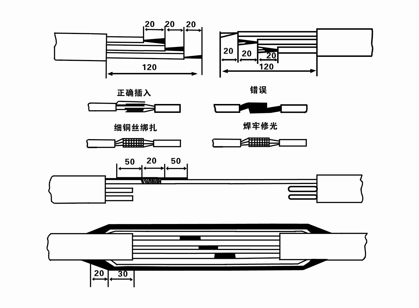
7. Cable joint, cut off a 120mm rubber sleeve from one end of the outgoing cable and the matching cable with an electrician's knifethen stagger the length of the three core wires in a stepped shape, peel off a 20mm copper core, scrape of the oxide layer on theoutside of the copper wire with a knife or sand cloth, and insert the two connected wire ends in palirs.
After tying the layer tightly with fine copper wire, solder it thoroughly and firmly, and sand of any. burrs on the surface. Then, forthe three joints, use polyvester insulation tape to wrap them in a semi stacked manner for three lavers. Wrap the two ends of thewrapping layer tightywith nyion thread,and then use a semi stacked method to wrap the tape for three layers. Wrap the outellayer with high-pressure insulation tape for three layers. Finally, fold the threestrands together and repeatedly wrap them for fivelayers with high-pressure tape. Each layer must be tightly tied, and the interlayer joints must be tight and fimm to prevent water frompenetrating and damaging the insulation, After wrapping, soak in water at room temperature of 20 ’c for 12 hours, and measurethe insulation resistance with a shaking table, which should not be less than 100M Ω
Lo schema del processo di cablaggio del cavo allegato è il seguente:
8. Utilizzare un multimetro per verificare se i cavi trifase sono collegati e se la resistenza CC è approssimativamente bilanciata.
9. Check whether the circuit and transformer capacity are overloaded, and then connect the overload protection switch or starting equipment. See Table 2 for specific models, and then
Pour a bucket of water into the water pump from the water pump outlet to lubricate the rubber bearings in the pump, and then place the submersible electric pump upright and steady.
Start (no more than one second) and check whether the steering direction is consistent with the steering sign. If not, swap any two connectors of the three-phase cable.
Then install the filter and prepare to go down the well. If used in special occasions (such as ditches, ditches, rivers, ponds, ponds, etc.), the electric pump must be reliably grounded.
(2)Attrezzature e strumenti di installazione:
1. Una coppia di catene di sollevamento per più di due tonnellate.
2. Un treppiede con altezza verticale non inferiore a quattro metri.
3. Due funi sospese (funi metalliche) che possono sopportare un peso superiore a una tonnellata (possono sopportare il peso di un set completo di pompe dell'acqua).
4. Installare due paia di morsetti (stecche).
5. Chiavi inglesi, martelli, cacciaviti, utensili e strumenti elettrici, ecc.
(3)Installazione dell'elettropompa:
1. Lo schema di installazione dell'elettropompa sommergibile è mostrato nella Figura 2. Le dimensioni specifiche di installazione sono riportate nella Tabella 3 "Elenco dimensioni di installazione dell'elettropompa sommersa".
2. Le elettropompe sommergibili con una prevalenza inferiore a 30 metri possono essere issate direttamente nel pozzo utilizzando tubi flessibili e funi metalliche o altre funi di canapa in grado di sopportare l'intero peso dell'intera macchina, dei tubi dell'acqua e dell'acqua nei tubi.
3. Le pompe con una prevalenza superiore a 30 metri utilizzano tubi in acciaio e la sequenza di installazione è la seguente:
①Use a clamp to clamp the upper end of the water pump part (the motor and water pump have been connected at this time), lift it with a hanging chain, and slowly tie it into the well until
Put the clamp on the wellhead and remove the hanging chain.
② Use another pair of clamps to clamp a pipe, lift it with a hanging chain 15 cm away from the flange, and lower it slowly. Between pipe flange and pump flange
Put the rubber pad in place and tighten the pipe and pump evenly with bolts, nuts and spring washers.
③ Sollevare leggermente la pompa sommergibile, rimuovere il morsetto sull'estremità superiore della pompa dell'acqua, legare saldamente il cavo al tubo dell'acqua con un nastro di plastica e legarlo lentamente finché il morsetto non viene posizionato sulla testa del pozzo.
④Utilizzare lo stesso metodo per collegare tutti i tubi dell'acqua al pozzo.
⑤Dopo aver collegato il cavo di uscita all'interruttore di controllo, è collegato all'alimentazione trifase.
(4) Cose da notare durante l'installazione:
1. If a jamming phenomenon is found during the pumping process, turn or pull the water pipe to overcome the jamming point. If various measures still do not work, please
Do not force the pump down to avoid damage to the submersible electric pump and the well.
2. Durante l'installazione, posizionare un tampone di gomma sulla flangia di ciascun tubo e serrarlo uniformemente.
3. Quando la pompa dell'acqua viene abbassata nel pozzo, deve essere posizionata al centro del tubo del pozzo per evitare che la pompa funzioni a lungo contro la parete del pozzo, provocando vibrazioni della pompa e spazzamento e bruciatura del motore .
4. Determinare la profondità della pompa dell'acqua sul fondo del pozzo in base alle condizioni di scorrimento della sabbia e del limo nel pozzo. Non seppellire la pompa nel fango. La distanza dalla pompa dell'acqua al fondo del pozzo non è generalmente inferiore a 3 metri (vedi Figura 2).
5. La profondità di ingresso dell'acqua della pompa dell'acqua non deve essere inferiore a 1-1,5 metri dal livello dinamico dell'acqua al nodo di ingresso dell'acqua (vedere Figura 2). In caso contrario, i cuscinetti della pompa dell'acqua potrebbero danneggiarsi facilmente.
6. L'alzata della pompa dell'acqua non può essere troppo bassa. Altrimenti, è necessario installare una valvola a saracinesca sulla tubazione dell'acqua della testa del pozzo per controllare il flusso della pompa al punto di flusso nominale per evitare che il motore venga sovraccaricato e bruciato a causa delle grandi portate.
7. Quando la pompa dell'acqua è in funzione, l'uscita dell'acqua dovrebbe essere continua e uniforme, la corrente dovrebbe essere stabile (nelle condizioni di lavoro nominali, generalmente non più del 10% della corrente nominale) e non dovrebbero esserci vibrazioni o rumore. Se si riscontra qualche anomalia, è necessario arrestare la macchina per scoprirne la causa ed eliminarla.
8. Durante l'installazione, prestare attenzione all'impostazione del filo di terra del motore (vedere Figura 2). Quando la tubazione dell'acqua è di acciaio, farla uscire dal morsetto di testa pozzo; quando il tubo dell'acqua è di plastica, collegarlo al punto di messa a terra dell'elettropompa.
- 1. Dopo aver installato la pompa sommersa, controllare nuovamente la resistenza di isolamento e la conduzione trifase dall'interruttore, controllare se lo strumento e il collegamento dell'apparecchiatura di avvio sono errati, se non ci sono problemi, è possibile avviare la macchina di prova. e osservare se le letture dell'indicatore dello strumento superano la tensione nominale e la corrente specificate sulla targhetta dopo l'avvio, e osservare se la pompa presenta fenomeni di rumore e vibrazione e metterla in funzione se tutto è normale.
- 2. Dopo il primo utilizzo della pompa per quattro ore, il motore deve essere spento per testare rapidamente la resistenza dell'isolamento termico e il suo valore non deve essere inferiore a 0,5 megaohm.
- 3.Dopo lo spegnimento, la pompa deve essere avviata dopo cinque minuti per evitare che la colonna d'acqua nel tubo venga completamente rifluita causando un'eccessiva corrente del motore e una bruciatura.
- 4. Dopo aver messo la pompa in funzionamento normale, per prolungarne la durata, è necessario verificare regolarmente se la tensione di alimentazione, la corrente di lavoro e la resistenza di isolamento sono normali. Se si riscontrano le seguenti condizioni, la pompa deve essere spenta immediatamente per risolvere il problema.
- 1 In the rated condition, the current exceeds 20%.
- 2 Il livello dinamico dell'acqua scende nella sezione di ingresso dell'acqua, causando acqua intermittente.
- 3 La pompa sommergibile presenta forti vibrazioni o rumore.
- 4 La tensione di alimentazione è inferiore a 340 volt.
- 5 Un fusibile è bruciato.
- 6 Il tubo di alimentazione dell'acqua è danneggiato.
- 7 The motor's thermal insulation resistance is lower than 0.5 megaohm.
- Unit disassembly:
- 1.Untie the cable tie, remove the pipeline part, and remove the wire plate.
- 2.screw down the water bolt, put the water in the motor chamber.
- 3.remove the filter, loose the fixed screw on the coupling to fix the motor shaft.
- 4.screw down the bolt connecting the water inlet section with the motor, and separate the pump from the motor (pay attention to the unit cushion when separating, to prevent the bending of the pump shaft)
- 5.the disassembly sequence of the pump is: (see figure 1) water inlet section, impeller, diversion shell, impeller...... check valve body, when removing the impeller, use special tools to loosen the conical sleeve of the fixed impeller first, and avoid bending and bruising the pump shaft in the process of disassembly.
- 6.the disassembly process of the motor is: (see figure 1) place the motor on the platform, and remove the nuts, base, shaft head locking nut, thrust plate, key, lower guide bearing seat and double head bolt from the bottom of the motor in turn, and then take out the rotor (pay attention not to damage the wire package) and finally remove the connecting section and upper guide bearing seat.
- 7.unit assembly: before assembly, the rust and dirt of the parts should be cleaned, and the mating surface and fasteners coated with sealant, and then assembled in the opposite order of disassembly (the motor shaft moves up and down after assembly for about one millimeter), after assembly, the coupling should be flexible, and then the filter screen test machine. Submersible pumps shall be taken out of the well for dismantling and maintenance according to Article 5 after a year of operation, or less than a year of operation but two years of diving time, and the worn parts shall be replaced.
This product is an efficient and durable submersible electric pump, suitable for a variety of environments and applications.In order to ensure the long-term use and stable performance of the product, we suggest that users pay special attention to drying the water in the motor cavity in winter to avoid freezing; in addition, the cable is coiled and tied, and properly stored in an environment without corrosive substances and gases, with a temperature below 40 °C. If the product is not used for a long time, attention should be paid to rust prevention treatment to ensure the life cycle and performance of the product.Whether for industrial use or for home use, this submersible electric pump can provide you with reliable pump service.
-
- Girante
- Manicotto dell'albero
- Manicotto dell'albero in gomma
-
Anello di tenuta
01 Presa d'acqua da pozzo profondo
02 Approvvigionamento idrico a molti piani
03 approvvigionamento idrico di montagna
04 torre d'acqua
05 Irrigazione agricola
06 irrigazione del giardino
07 presa d'acqua del fiume
08 acqua sanitaria


