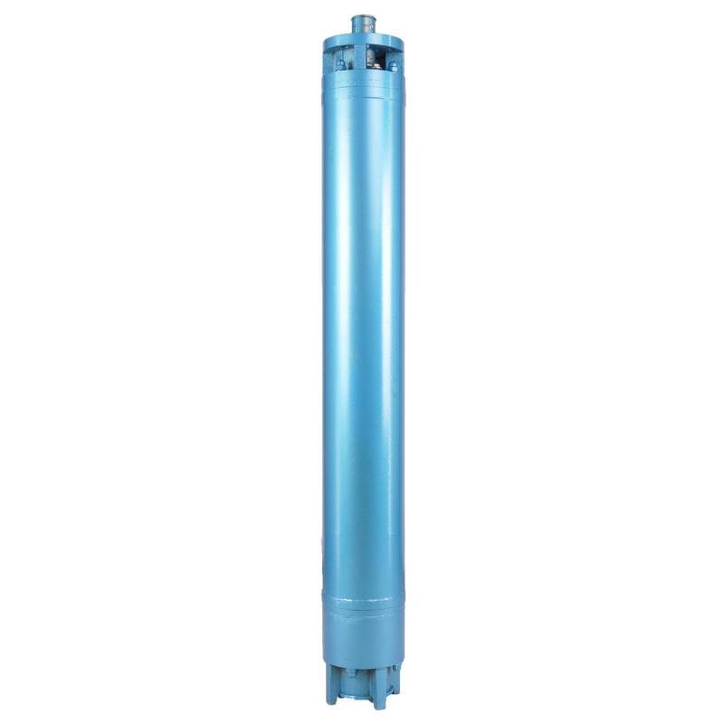
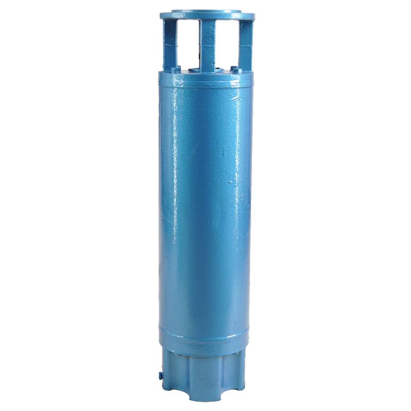
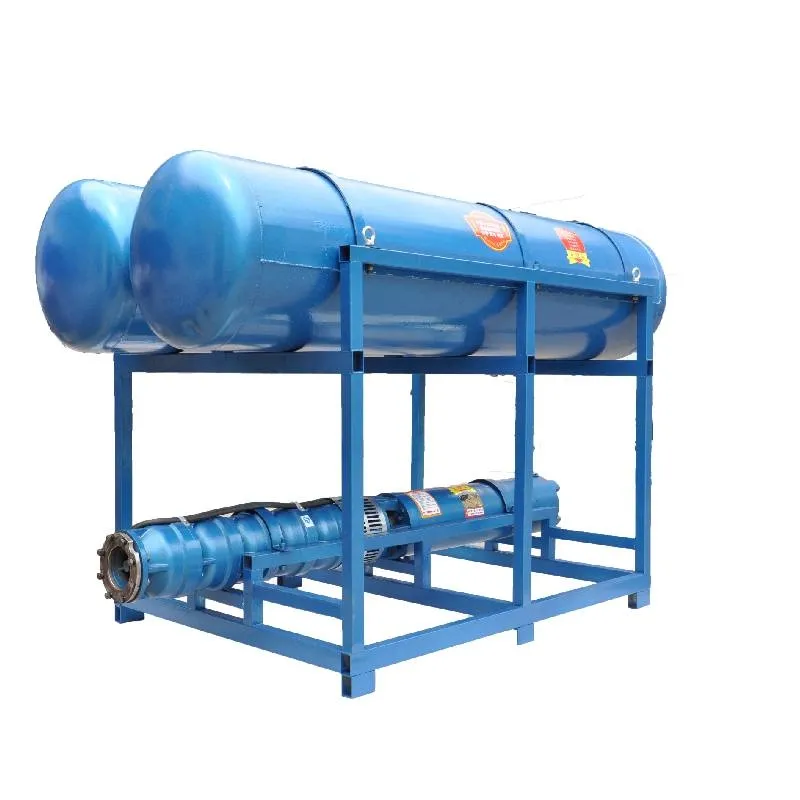
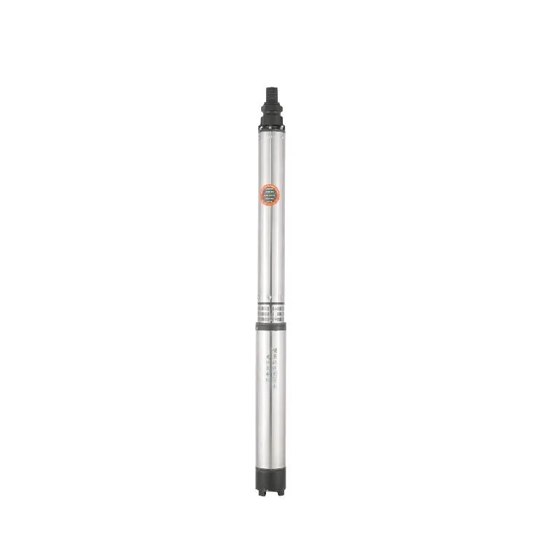
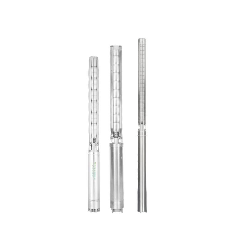
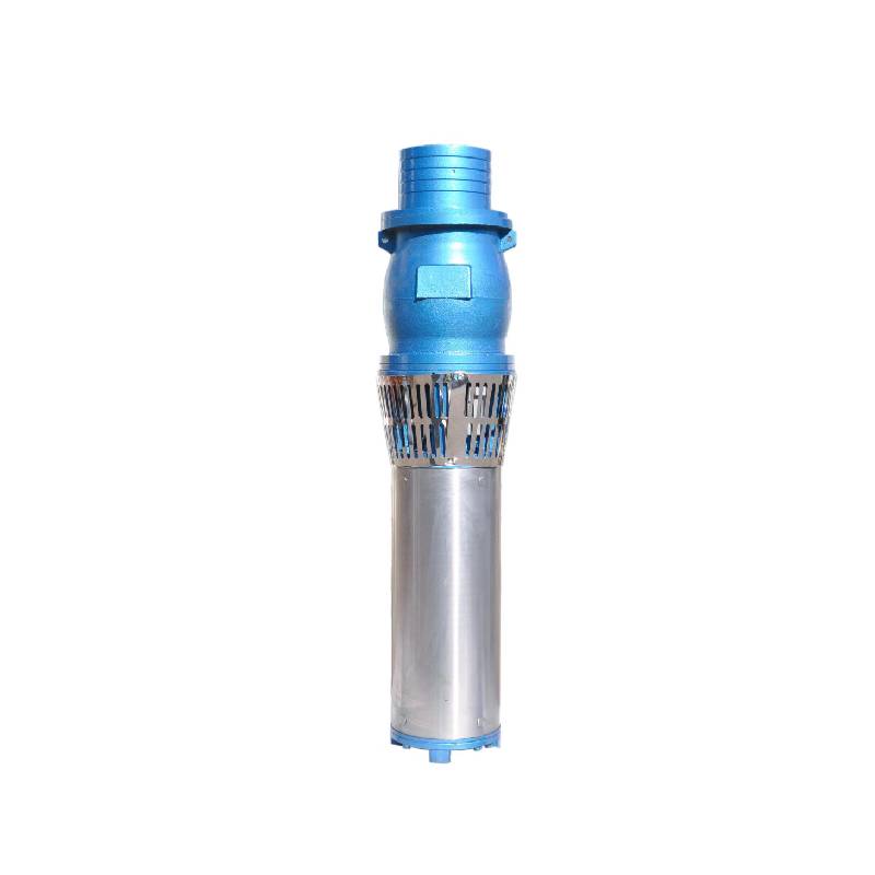
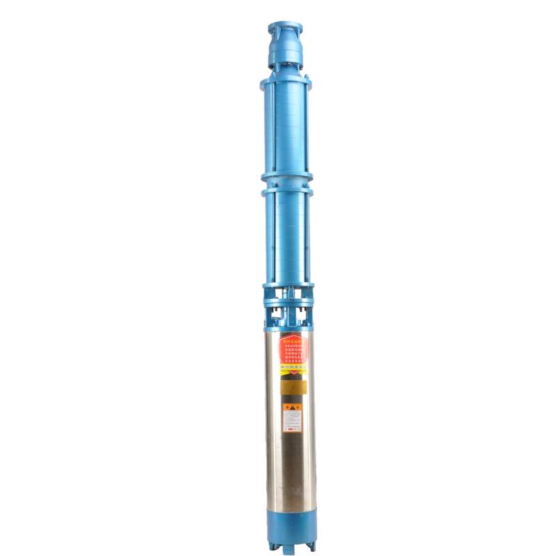
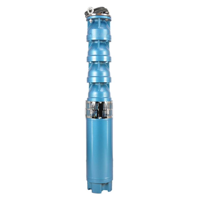
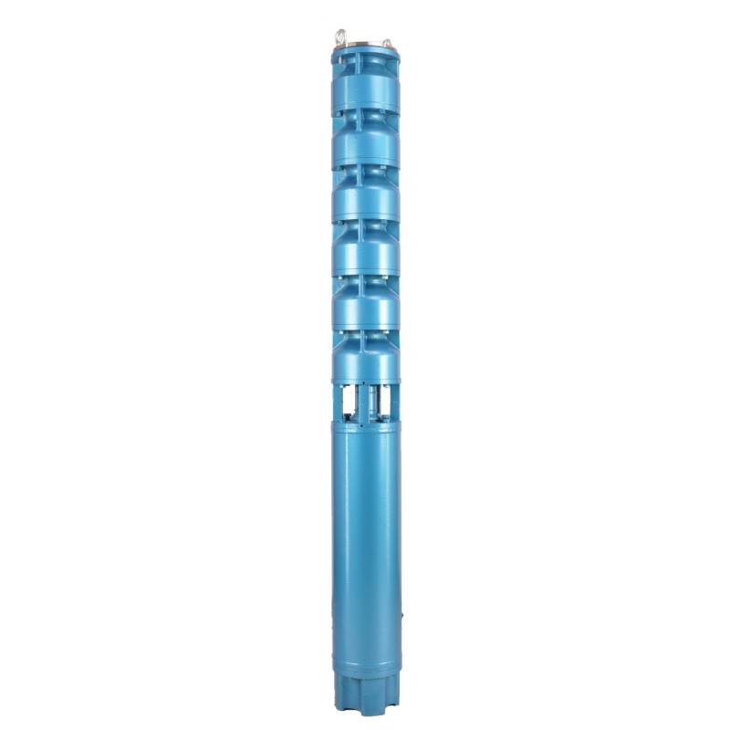
The product adopts special water-resistant wire for motor winding, with excellent characteristics such as high frequency shock resistance, pulse peak voltage shock resistance and high temperature aging resistance. The frequency conversion winding design ensures the motor to operate smoothly between 1Hz and 50Hz for a long time, making the frequency conversion deep well pump more energy saving and longer service life.
We are honored to introduce our products, this product provides three-phase AC 380V power supply (tolerance of ± 5%), 50HZ voltage (tolerance of ± 1%). At the same time, our products require strict water quality requirements: water temperature is not higher than 20 °C; solid impurities content (mass ratio) is not greater than 0.01%; PH value (pH) is 6.5-8.5; hydrogen sulfide content is not greater than 1.5mg/L; chloride ion content is not greater than 400mg/L. The motor adopts closed or water-filled wet structure, which must be filled with clean water before use to prevent empty. Tighten the water charging and deflating bolts before use, otherwise, it is not allowed to use. The submersible pump must be completely immersed in water to work, the immersion depth shall not exceed 70 meters, and the distance between the bottom of the submersible pump and the bottom of the well shall not be less than 3 meters. The well water flow shall meet the output and continuous operation requirements of the submersible pump, and the output of the submersible pump shall be controlled at 0.7-1.2 times of the rated flow. The well must be vertical, and the submersible pump can not be used horizontally or inverted, but only vertically. The submersible pump must be equipped with cables according to requirements, and is equipped with external overload protection devices. It is strictly prohibited to conduct no-load tests on the pump without water. Our products guarantee to provide you with high quality and stable performance, while meeting your needs to ensure safe and reliable.
| Modeli | Akış (m3/saat) | KAFA (M) |
Dönme hızı (değişim noktası) |
Su Pompası(%) | Çıkış çap (mm) |
İyi uygulanabilir çap(mm) |
Oy power(KW) |
Oy gerilim(V) |
Oy akım(A) |
Motor verimliliği (%) | power factorcosφ | Birim Radyal Maksimum boyut (mm) |
|||||||||
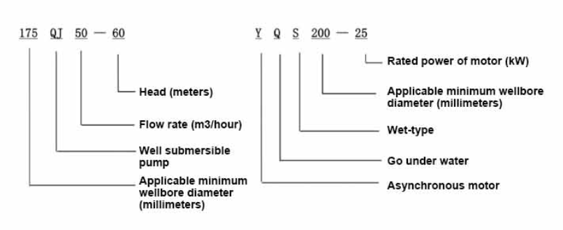
| 175QJ10-42 | 10 | 42 | 2850 | 53 | 50 | 175üstünde | 3 | 380 | 7.8 | 74.0 | 0.79 | 168 | |||||||||
| 175QJ10-56 | 56 | 4 | 10.1 | 76.0 | 0.79 | ||||||||||||||||
| 175QJ10-70 | 70 | 4 | 10.1 | 76.0 | 0.79 | ||||||||||||||||
| 175QJ10-84 | 84 | 5.5 | 13.6 | 77.0 | 0.8 | ||||||||||||||||
| 175QJ10-112 | 112 | 7.5 | 18.4 | 77.5 | 0.8 | ||||||||||||||||
| 175QJ10-126 | 126 | 7.5 | 18.4 | 77.5 | 0.8 | ||||||||||||||||
| 175QJ10-140 | 140 | 9.2 | 22.1 | 78.0 | 0.81 | ||||||||||||||||
| 175QJ15-42 | 15 | 42 | 2850 | 58 | 50 | 175üstünde | 4 | 380 | 10.1 | 76.0 | 0.79 | 168 | |||||||||
| 175QJ15-55 | 55 | 5.5 | 13.6 | 77.0 | 0.8 | ||||||||||||||||
| 175QJ15-65 | 65 | 5.5 | 13.6 | 77.0 | 0.8 | ||||||||||||||||
| 175QJ15-85 | 85 | 7.5 | 18.4 | 77.5 | 0.8 | ||||||||||||||||
| 175QJ15-112 | 112 | 9.2 | 22.1 | 78.0 | 0.81 | ||||||||||||||||
| 175QJ20-26 | 20 | 26 | 2850 | 64 | 50 | 175üstünde | 3 | 380 | 7.8 | 74.0 | 0.79 | 168 | |||||||||
| 175QJ20-39 | 39 | 4 | 10.1 | 76.0 | 0.79 | ||||||||||||||||
| 175QJ20-52 | 52 | 5.5 | 13.6 | 77.0 | 0.8 | ||||||||||||||||
| 175QJ20-78 | 78 | 7.5 | 18.4 | 77.5 | 0.8 | ||||||||||||||||
| 175QJ20-91 | 91 | 9.2 | 22.1 | 78.0 | 0.81 | ||||||||||||||||
| 175QJ20-104 | 104 | 11 | 26.1 | 79.0 | 0.81 | ||||||||||||||||
| 175QJ20-130 | 130 | 13 | 30.1 | 80.0 | 0.82 | ||||||||||||||||
| 175QJ20-156 | 156 | 15 | 34.7 | 80.0 | 0.82 | ||||||||||||||||
| 175QJ20-182 | 187 | 18.5 | 42.6 | 80.5 | 0.82 | ||||||||||||||||
| 175QJ20-208 | 208 | 22 | 49.7 | 81.0 | 0.83 | ||||||||||||||||
| 175QJ20-247 | 247 | 25 | 56.5 | 81.0 | 0.83 | ||||||||||||||||
| 175QJ20-273 | 273 | 30 | 66.6 | 81.5 | 0.84 | ||||||||||||||||
| 175QJ20-299 | 299 | 30 | 66.6 | 81.5 | 0.84 | ||||||||||||||||
| 175QJ20-325 | 325 | 32 | 71.0 | 81.5 | 0.84 | ||||||||||||||||
| 175QJ20-364 | 364 | 37 | 82.1 | 81.5 | 0.84 | ||||||||||||||||
| 175QJ25-26 | 25 | 26 | 2850 | 66 | 65 | 175üstünde | 3 | 380 | 7.8 | 74.0 | 0.79 | 168 | |||||||||
| 175QJ25-39 | 39 | 5.5 | 13.6 | 77.0 | 0.8 | ||||||||||||||||
| 175QJ25-65 | 25 | 65 | 2850 | 66 | 65 | 175üstünde | 7.5 | 380 | 18.4 | 77.5 | 0.8 | 168 | |||||||||
| 175QJ25-78 | 78 | 9.2 | 22.1 | 78.0 | 0.81 | ||||||||||||||||
| 175QJ25-91 | 91 | 11 | 26.1 | 79.0 | 0.81 | ||||||||||||||||
| 175QJ25-104 | 104 | 13 | 30.1 | 80.0 | 0.82 | ||||||||||||||||
| 175QJ25-130 | 130 | 15 | 34.7 | 80.0 | 0.82 | ||||||||||||||||
| 175QJ25-156 | 156 | 18.5 | 42.6 | 80.5 | 0.82 | ||||||||||||||||
| 175QJ25-182 | 182 | 22 | 49.7 | 81.0 | 0.83 | ||||||||||||||||
| 175QJ25-208 | 208 | 25 | 56.5 | 81.0 | 0.83 | ||||||||||||||||
| 175QJ25-221 | 221 | 30 | 66.6 | 81.5 | 0.84 | ||||||||||||||||
| 175QJ25-247 | 247 | 30 | 66.6 | 81.5 | 0.84 | ||||||||||||||||
| 175QJ25-260 | 260 | 32 | 71.0 | 81.5 | 0.84 | ||||||||||||||||
| 175QJ25-299 | 299 | 37 | 82.1 | 81.5 | 0.84 | ||||||||||||||||
| 175QJ30-30 | 30 | 30 | 2850 | 67 | 80 | 175üstünde | 4 | 380 | 10.1 | 76.0 | 0.79 | 168 | |||||||||
| 175QJ30-40 | 40 | 5.5 | 13.6 | 77.0 | 0.8 | ||||||||||||||||
| 175QJ32-24 | 32 | 24 | 2850 | 67 | 80 | 175üstünde | 4 | 380 | 10.1 | 76.0 | 0.79 | 168 | |||||||||
| 175QJ32-36 | 36 | 5.5 | 13.6 | 77.0 | 0.8 | ||||||||||||||||
| 175QJ32-48 | 48 | 7.5 | 18.4 | 77.5 | 0.8 | ||||||||||||||||
| 175QJ32-60 | 60 | 9.2 | 22.1 | 78.0 | 0.81 | ||||||||||||||||
| 175QJ32-72 | 72 | 11 | 26.1 | 79.0 | 0.81 | ||||||||||||||||
| 175QJ32-84 | 84 | 13 | 30.1 | 80.0 | 0.82 | ||||||||||||||||
| 175QJ32-96 | 96 | 15 | 34.7 | 80.0 | 0.82 | ||||||||||||||||
| 175QJ32-120 | 120 | 18.5 | 42.6 | 80.5 | 0.82 | ||||||||||||||||
| 175QJ32-144 | 144 | 22 | 49.7 | 81.0 | 0.83 | ||||||||||||||||
| 175QJ32-168 | 168 | 25 | 56.5 | 81.0 | 0.83 | ||||||||||||||||
| 175QJ32-180 | 180 | 30 | 66.6 | 81.5 | 0.84 | ||||||||||||||||
| 175QJ32-192 | 192 | 30 | 66.6 | 81.5 | 0.84 | ||||||||||||||||
| 175QJ32-204 | 204 | 32 | 71.0 | 81.5 | 0.84 | ||||||||||||||||
| 175QJ32-240 | 240 | 37 | 82.1 | 81.5 | 0.84 | ||||||||||||||||
| 175QJ35-60 | 35 | 60 | 2850 | 67 | 80 | 175üstünde | 10 | 380 | 25.0 | 78.0 | 0.78 | 168 | |||||||||
| 175QJ35-75 | 75 | 13 | 30.1 | 80.0 | 0.82 | ||||||||||||||||
| 175QJ35-100 | 100 | 17 | 40.9 | 80.0 | 0.79 | ||||||||||||||||
| 175QJ40-24 | 40 | 24 | 2850 | 70 | 80 | 175üstünde | 5.5 | 380 | 13.6 | 77.0 | 0.8 | 168 | |||||||||
| 175QJ40-30 | 30 | 5.5 | 13.6 | 77.0 | 0.8 | ||||||||||||||||
| 175QJ40-36 | 36 | 7.5 | 18.4 | 77.5 | 0.8 | ||||||||||||||||
| 175QJ40-48 | 48 | 9.2 | 22.1 | 78.0 | 0.81 | ||||||||||||||||
| 175QJ40-60 | 60 | 11 | 26.1 | 79.0 | 0.81 | ||||||||||||||||
| 175QJ40-72 | 72 | 13 | 30.1 | 80.0 | 0.82 | ||||||||||||||||
| 175QJ40-84 | 84 | 15 | 34.7 | 80.0 | 0.82 | ||||||||||||||||
| 175QJ40-96 | 96 | 18.5 | 42.6 | 80.5 | 0.82 | ||||||||||||||||
| 175QJ40-120 | 120 | 22 | 49.7 | 81.0 | 0.83 | ||||||||||||||||
| 175QJ40-132 | 132 | 25 | 56.5 | 81.0 | 0.83 | ||||||||||||||||
| 175QJ40-144 | 144 | 30 | 66.6 | 81.5 | 0.84 | ||||||||||||||||
| 175QJ40-156 | 156 | 30 | 66.6 | 81.5 | 0.84 | ||||||||||||||||
| 175QJ40-168 | 168 | 32 | 71.0 | 81.5 | 0.84 | ||||||||||||||||
| 175QJ40-192 | 192 | 37 | 82.1 | 81.5 | 0.84 | ||||||||||||||||
| 175QJ50-24 | 50 | 24 | 2850 | 72 | 80 | 175üstünde | 5.5 | 380 | 13.6 | 77.0 | 0.8 | 168 | |||||||||
| 175QJ50-36 | 36 | 9.2 | 22.1 | 78.0 | 0.81 | ||||||||||||||||
| 175QJ50-48 | 48 | 11 | 26.1 | 79.0 | 0.81 | ||||||||||||||||
| 175QJ50-60 | 60 | 13 | 30.1 | 80.0 | 0.82 | ||||||||||||||||
| 175QJ50-70 | 70 | 17 | 40.9 | 80.0 | 0.79 | ||||||||||||||||
| 175QJ50-84 | 84 | 18.5 | 42.6 | 80.5 | 0.82 | ||||||||||||||||
| 175QJ50-96 | 96 | 22 | 49.7 | 81.0 | 0.83 | ||||||||||||||||
| 175QJ50-108 | 108 | 25 | 56.5 | 81.0 | 0.83 | ||||||||||||||||
| 175QJ50-120 | 120 | 30 | 66.6 | 81.5 | 0.84 | ||||||||||||||||
| 175QJ50-132 | 132 | 30 | 66.6 | 81.5 | 0.84 | ||||||||||||||||
| 175QJ50-144 | 144 | 32 | 71.0 | 81.5 | 0.84 | ||||||||||||||||
| 175QJ50-156 | 156 | 37 | 82.1 | 81.5 | 0.84 | ||||||||||||||||
| 175QJ63-22 | 63 | 22 | 2850 | 72 | 80 | 175üstünde | 7.5 | 380 | 18.4 | 77.5 | 0.8 | 168 | |||||||||
| 175QJ63-44 | 44 | 13 | 30.1 | 80.0 | 0.82 | ||||||||||||||||
| 175QJ63-55 | 55 | 15 | 34.7 | 80.0 | 0.82 | ||||||||||||||||
| 175QJ63-66 | 66 | 18.5 | 42.6 | 80.5 | 0.82 | ||||||||||||||||
| 175QJ63-77 | 77 | 22 | 49.7 | 81.0 | 0.83 | ||||||||||||||||
| 175QJ63-88 | 88 | 25 | 56.5 | 81.0 | 0.83 | ||||||||||||||||
| 175QJ63-99 | 63 | 99 | 2850 | 72 | 80 | 175üstünde | 30 | 380 | 66.6 | 81.5 | 0.84 | 168 | |||||||||
| 175QJ63-110 | 110 | 32 | 71.0 | 81.5 | 0.84 | ||||||||||||||||
| 175QJ63-132 | 132 | 37 | 82.1 | 81.5 | 0.84 | ||||||||||||||||
| 175QJ80-9 | 80 | 9 | 2850 | 73 | 100 | 175üstünde | 4 | 380 | 10.1 | 76.0 | 0.79 | 168 | |||||||||
| 175QJ80-18 | 18 | 7.5 | 18.4 | 77.5 | 0.8 | ||||||||||||||||
| 175QJ80-27 | 27 | 11 | 26.1 | 79.0 | 0.81 | ||||||||||||||||
| 175QJ80-36 | 36 | 15 | 34.7 | 80.0 | 0.82 | ||||||||||||||||
| 175QJ80-45 | 45 | 18.5 | 42.6 | 80.5 | 0.82 | ||||||||||||||||
| 175QJ80-54 | 54 | 22 | 49.7 | 81.0 | 0.83 | ||||||||||||||||
| 175QJ80-63 | 63 | 25 | 56.5 | 81.0 | 0.83 | ||||||||||||||||
| 175QJ80-72 | 72 | 25 | 56.5 | 81.0 | 0.83 | ||||||||||||||||
| 175QJ80-81 | 81 | 30 | 66.6 | 81.5 | 0.84 | ||||||||||||||||
| 175QJ80-90 | 90 | 32 | 71.0 | 81.5 | 0.84 | ||||||||||||||||
| 175QJ80-98 | 98 | 37 | 82.1 | 81.5 | 0.84 | ||||||||||||||||
This well submersible pump is a pump suitable for clean water. Digging new wells and pumping sediment and turbid water are strictly prohibited. The voltage grade of the well pump is 380V/50HZ. Submersible motors with other voltage grades need to be customized. Underground cables must use waterproof cables and must be equipped with starting equipment, such as distribution boxes, etc. The starting equipment should have common comprehensive motor protection functions, such as overload short circuit protection, phase loss protection, undervoltage protection, grounding protection and idling protection, etc. In abnormal cases, the protection device should be tripped in time. During installation and use, the pump must be reliably grounded. It is prohibited to push and pull the switch when hands and feet are wet. The power supply must be cut off before installation and maintenance of the pump. The place where the pump is used must be set up with obvious "anti-electric shock" marks. Before going down the well or installation, the motor must be injected with distilled water or non-corrosive clear cold water in the inner cavity, and the intake/drain bolts must be tightened. When testing the pump on the ground, water must be injected into the pump chamber to lubricate the rubber bearings. The instant start time should not exceed one second to check whether the direction is correct. The same as the steering instructions. Pay attention to safety when the pump is upright to prevent tilting and injury. Strictly in accordance with the provisions of the pump lift and flow range, to prevent the pump flow at low lift or in high lift pull too large, resulting in extreme wear of thrust bearings and other components, the motor due to overload and burn. After put into the well, the measurement of the motor and the ground insulation resistance value, not less than 100M. After the start, regular observation of voltage and current, and check the motor winding insulation is in line with the requirements of the provisions. If the temperature of the storage site is below the freezing point, the water in the pump chamber should be drained to prevent the water in the motor chamber from freezing and damaging the motor due to low temperature.
Yapının kısa tanıtımı: Pompa parçası esas olarak pompa mili, pervane, saptırma kabuğu, kauçuk yatak, çek valf gövdesi (isteğe bağlı parçalar) ve diğer bileşenlerden oluşur. Motor kısmı esas olarak taban, basınç ayar filmi, baskı yatağı, baskı plakası, alt kılavuz yatak yuvası, stator, rotor, üst kılavuz yatak yuvası, kum halkası, su giriş bölümü, kablo ve diğer bileşenlerden oluşur.
Ürünün ana özellikleri şunları içerir:
1.The motor is a water-filled wet submersible three-phase asynchronous motor, the motor cavity is full of clean water, used to cool the motor and lubricate the bearing, the pressure regulating film at the bottom of the motor is used to adjust the expansion and contraction pressure difference of the water inside the body caused by the change of the temperature rise of the motor.
2.In order to prevent the sand in the well water from entering the motor, the upper end of the motor shaft is equipped with two oil seals, and a sand ring is installed to form a sand prevention structure.
3.In order to prevent the pump shaft from running up when starting, the pump shaft and the motor shaft are connected by a coupling, and an upper thrust bearing is installed at the lower part of the motor.
4.The lubrication of the motor and the pump bearing is water lubrication.
5.The motor stator winding is made of high quality submersible motor winding wire, with high insulation performance.
6.The pump is designed by computer CAD, with simple structure and good technical performance.

(1)Kurulumdan önce hazırlık:
1. Dalgıç pompanın kılavuzda belirtilen kullanım koşullarını ve kapsamını karşılayıp karşılamadığını kontrol edin.
2. Dalgıç pompanın maksimum dış çapına eşit çapta ağır bir cisim kullanarak kuyu deliğinin iç çapının dalgıç pompaya uyup uymadığını ve kuyu derinliğinin kurulum gereksinimlerini karşılayıp karşılamadığını ölçün.
3. Kuyu deliğinin temiz olup olmadığını ve kuyu suyunun bulanık olup olmadığını kontrol edin. Dalgıç elektrikli pompanın zamanından önce hasar görmesini önlemek için, Welor pompası çamurunu ve kum suyunu yıkamak için asla dalgıç elektrikli pompa kullanmayın.
4. Kaynaklı montaj kelepçesinin konumunun uygun olup olmadığını ve tüm ünitenin kalitesine dayanıp dayanamayacağını kontrol edin.
5. Dalgıç pompa bileşenlerinin eksiksiz olup olmadığını ve kılavuzdaki montaj şemasına göre düzgün şekilde monte edilip edilmediğini kontrol edin. Filtre süzgecini çıkarın ve esnek bir şekilde dönüp dönmediğini görmek için kaplini döndürün.
6. Su vidasını sökün ve motor boşluğunu temiz, aşındırıcı olmayan suyla doldurun (not: doldurduğunuzdan emin olun), ardından su vidasını sıkın. 12 saatlik su enjeksiyonundan sonra motorun izolasyon direnci, 500V sarsma tablası ile ölçüldüğünde 150M Q'dan az olmamalıdır.
7. Cable joint, cut off a 120mm rubber sleeve from one end of the outgoing cable and the matching cable with an electrician's knifethen stagger the length of the three core wires in a stepped shape, peel off a 20mm copper core, scrape of the oxide layer on theoutside of the copper wire with a knife or sand cloth, and insert the two connected wire ends in palirs.After tying the layer tightly with fine copper wire, solder it thoroughly and firmly, and sand of any. burrs on the surface. Then, forthe three joints, use polyvester insulation tape to wrap them in a semi stacked manner for three lavers. Wrap the two ends of thewrapping layer tightywith nyion thread,and then use a semi stacked method to wrap the tape for three layers. Wrap the outellayer with high-pressure insulation tape for three layers. Finally, fold the threestrands together and repeatedly wrap them for fivelayers with high-pressure tape. Each layer must be tightly tied, and the interlayer joints must be tight and fimm to prevent water frompenetrating and damaging the insulation, After wrapping, soak in water at room temperature of 20 ’c for 12 hours, and measurethe insulation resistance with a shaking table, which should not be less than 100M Ω
Ekli kablo bağlantı işlemi şeması aşağıdaki gibidir: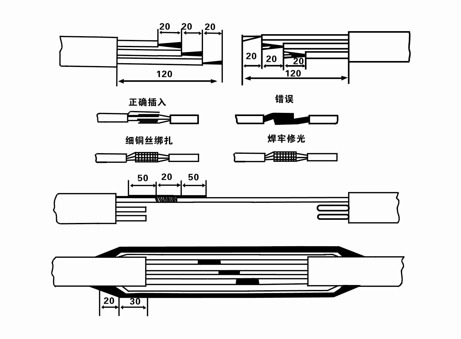
8. Üç fazlı kabloların bağlı olup olmadığını ve DC direncinin yaklaşık olarak dengeli olup olmadığını kontrol etmek için bir multimetre kullanın.
9. Devrenin ve transformatör kapasitesinin aşırı yüklü olup olmadığını kontrol edin ve ardından aşırı yük koruma anahtarını veya başlatma ekipmanını bağlayın. Belirli modeller için Tablo 2'ye bakın ve ardından pompadaki kauçuk yatakları yağlamak için su pompası çıkışından su pompasına bir kova su dökün ve ardından dalgıç elektrikli pompayı dik ve sabit bir şekilde yerleştirin.Başlat (bir saniyeden fazla değil) ve direksiyon yönünün direksiyon işaretiyle tutarlı olup olmadığını kontrol edin. Değilse, üç fazlı kablonun herhangi iki konnektörünü değiştirin. Ardından filtreyi takın ve kuyuya inmeye hazırlanın. Özel durumlarda (hendek, hendek, nehir, gölet, gölet vb.) kullanıldığında elektrikli pompanın güvenilir bir şekilde topraklanması gerekir.
(2) Kurulum ekipmanı ve araçları:
1. İki tondan fazla yük için bir çift kaldırma zinciri.
2. Dikey yüksekliği dört metreden az olmayan bir tripod.
3. Bir tondan fazla ağırlık taşıyabilen (komple bir su pompası setinin ağırlığını taşıyabilen) iki askı halatı (tel halatlar).
4. İki çift kelepçe (atel) takın.
5. Anahtarlar, çekiçler, tornavidalar, elektrikli aletler ve aletler vb.
(3)Elektrikli pompa kurulumu:
1. Dalgıç elektrikli pompanın kurulum şeması Şekil 2'de gösterilmektedir. Özel kurulum boyutları Tablo 3 "Dalgıç Elektrikli Pompanın Kurulum Boyutları Listesi"nde gösterilmektedir.
2. Yüksekliği 30 metreden az olan dalgıç elektrikli pompalar, tüm makinenin tüm ağırlığını, su borularını ve borulardaki suyu taşıyabilecek hortumlar ve tel halatlar veya diğer kenevir halatlar kullanılarak doğrudan kuyuya çekilebilir.
3. 30 metreden fazla basma yüksekliği olan pompalarda çelik borular kullanılır ve kurulum sırası aşağıdaki gibidir:
①Su pompası parçasının üst ucunu kelepçelemek için bir kelepçe kullanın (motor ve su pompası şu anda bağlanmıştır), asılı bir zincirle kaldırın ve kelepçeyi kuyu başına takıp çıkarıncaya kadar yavaşça kuyuya bağlayın. asılı zincir.
② Boruyu kelepçelemek için başka bir çift kelepçe kullanın, asılı zincirle flanştan 15 cm uzağa kaldırın ve yavaşça indirin. Boru flanşı ile pompa flanşı arasında Lastik tamponu yerine yerleştirin ve boruyu sıkın ve cıvatalar, somunlar ve yaylı rondelalarla eşit şekilde pompalayın.
③ Dalgıç pompayı hafifçe kaldırın, su pompasının üst ucundaki kelepçeyi çıkarın, kabloyu plastik bir bantla su borusuna sıkıca bağlayın ve kelepçe kuyu başına yerleşinceye kadar yavaşça bağlayın.
④Tüm su borularını kuyuya bağlamak için aynı yöntemi kullanın.
⑤Çıkış kablosu kontrol anahtarına bağlandıktan sonra üç fazlı güç kaynağına bağlanır.
(4)Kurulum sırasında dikkat edilmesi gerekenler:
1. Pompalama işlemi sırasında bir sıkışma durumu tespit edilirse, sıkışma noktasını aşmak için su borusunu çevirin veya çekin. Çeşitli önlemler hala işe yaramıyorsa, lütfen dalgıç elektrikli pompaya ve kuyuya zarar vermemek için pompayı aşağıya doğru zorlamayın.
2. Montaj sırasında her borunun flanşına lastik tampon yerleştirilmeli ve eşit şekilde sıkılmalıdır.
3. Su pompası kuyuya indirildiğinde, pompanın uzun süre kuyu duvarına karşı çalışıp pompanın titreşmesine ve motorun süpürüp yanmasına neden olmaması için kuyu borusunun ortasına yerleştirilmelidir. .
4. Kuyudaki akma kum ve silt durumuna göre su pompasının kuyu dibine kadar olan derinliğini belirleyin. Pompayı çamura gömmeyin. Su pompasından kuyu tabanına kadar olan mesafe genellikle 3 metreden az değildir (bkz. Şekil 2).
5. Su pompasının su giriş derinliği, dinamik su seviyesinden su giriş düğümüne kadar 1-1,5 metreden az olmamalıdır (bkz. Şekil 2). Aksi takdirde su pompası yatakları kolaylıkla zarar görebilir.
6. Su pompasının kaldırma kuvveti çok düşük olamaz. Aksi takdirde, motorun aşırı yüklenmesini ve büyük akış hızları nedeniyle yanmasını önlemek amacıyla pompa akışını nominal akış noktasında kontrol etmek için kuyu başı su boru hattına bir sürgülü vana takılması gerekir.
7. Su pompası çalışırken, su çıkışı sürekli ve eşit olmalı, akım sabit olmalı (nominal çalışma koşulları altında, genellikle nominal akımın 'undan fazla olmamalıdır) ve titreşim veya gürültü olmamalıdır. Herhangi bir anormallik varsa nedeninin bulunup ortadan kaldırılması için makine durdurulmalıdır.
8. Montajı yaparken motor topraklama kablosunun ayarına dikkat edin (bkz. Şekil 2). Su borusu çelik bir boru olduğunda, onu kuyu başı kelepçesinden geçirin; Su borusu plastik bir boru ise, onu elektrikli pompanın topraklama işaretinden geçirin.
- 1.After installing the submersible pump, recheck the insulation resistance and three-phase continuity switch, check whether there is any error in the connection between the instrument and the starting equipment.If there is no problem, you can start to test the machine. After starting, observe whether the indication reading of each instrument is correct.If the rated voltage and current specified on the nameplate are exceeded, please observe whether the pump has noise or vibration.If everything is normal, it can be put into operation. After the pump runs for the first time for four hours, the motor thermal insulation resistance should be closed and tested quickly. Its value should not be less than 0.5 megaohm. After the pump stops, it should be restarted after five minutes to prevent the water column in the pipeline from completely reversing, which will cause the motor to burn out due to excessive current.
- 2.After the pump is put into normal operation, in order to prolong its service life, it is necessary to check whether the supply voltage, working current and insulation resistance are normal regularly. If the following conditions are found, the machine should be stopped immediately to troubleshoot.
- 1.Under the rated working condition, the current exceeds 20%.
- 2.The dynamic water level drops to the water inlet section, resulting in intermittent water.
- 3.The submersible pump has severe vibration or noise.
- 4.The supply voltage is lower than 340 volts.
- 5.A fuse is burned out.
- 6.The water pipeline is damaged.
- 7.The motor's insulation resistance to the geothermal state is lower than 0.5 megaohm.
- 3.Unit disassembly:
- - Kablo bağını çözün, boru hattı parçasını çıkarın ve tel plakayı çıkarın.
- - screw down the water bolt, put out the water in the motor chamber.
- - filtreyi çıkarın, motor milini sabitlemek için kaplin üzerindeki sabit vidayı gevşetin.
- 4.screw down the bolt connecting the water inlet section with the motor, and separate the pump from the motor (pay attention to the unit cushion when separating, to prevent the bending of the pump shaft)
- 5.the disassembly sequence of the pump is: (see figure 1) water inlet section, impeller, diversion shell, impeller...... check valve body, when removing the impeller, use special tools to loosen the conical sleeve of the fixed impeller first, and avoid bending and bruising the pump shaft in the process of disassembly.
- 6.the disassembly process of the motor is: (see figure 1) place the motor on the platform, and remove the nuts, base, shaft head locking nut, thrust plate, key, lower guide bearing seat and double head bolt from the bottom of the motor in turn, and then take out the rotor (pay attention not to damage the wire package) and finally remove the connecting section and upper guide bearing seat.
- 7.unit assembly: before assembly, the rust and dirt of the parts should be cleaned, and the mating surface and fasteners coated with sealant, and then assembled in the opposite order of disassembly (the motor shaft moves up and down after assembly for about one millimeter), after assembly, the coupling should be flexible, and then the filter screen test machine. Submersible pumps shall be taken out of the well for dismantling and maintenance according to Article 5 after a year of operation, or less than a year of operation but two years of diving time, and the worn parts shall be replaced.
1, motor boşluğundaki suyu boşaltın (özellikle kışın motorun donmasını önlemek için) ve kabloyu iyice bağlayın.
2, store in an indoor room without corrosive substances and gases, with a temperature below 40 °C.
3, uzun süreli kullanımda dalgıç pompaların paslanmaya karşı korunmasına dikkat edilmelidir.
- Pervane
- Mil kovanı
- Kauçuk mil kovanı
-
Conta bileziği
01 Derin kuyu suyu alımı
02 Yüksek binalara su temini
03 dağ su temini
04 kule suyu
05 Tarımsal sulama
06 bahçe sulama
07 nehir suyu girişi
08 evsel su


