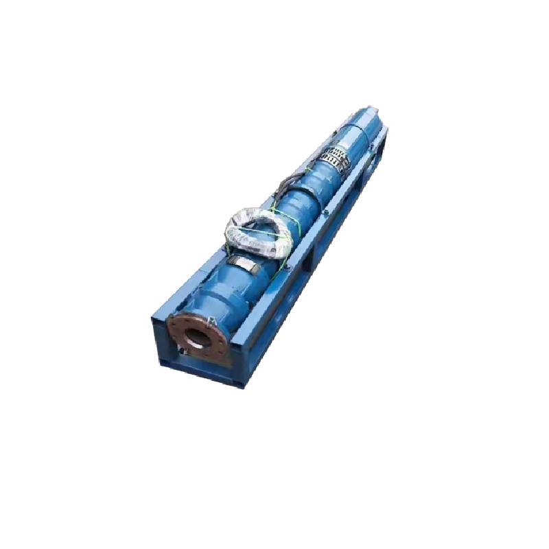
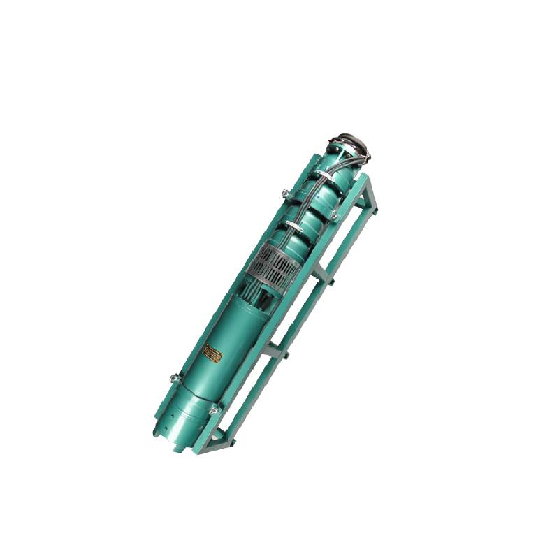
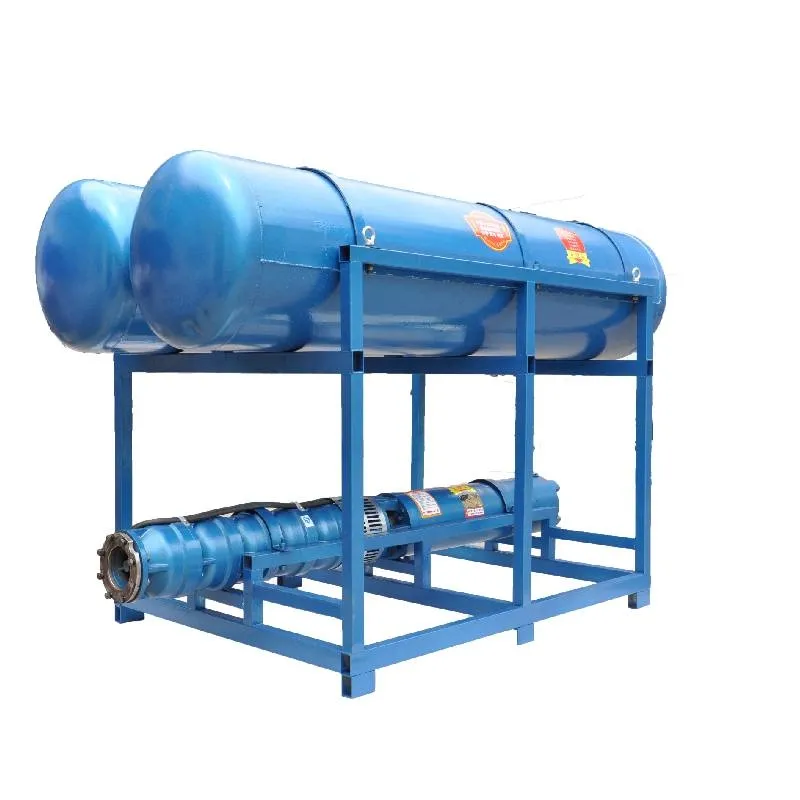
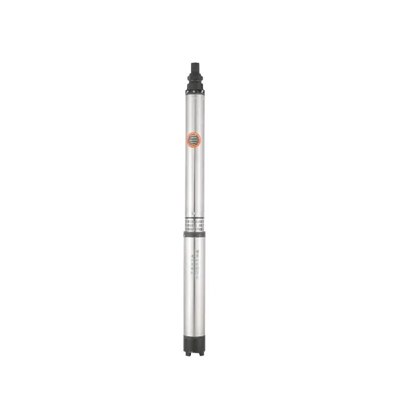
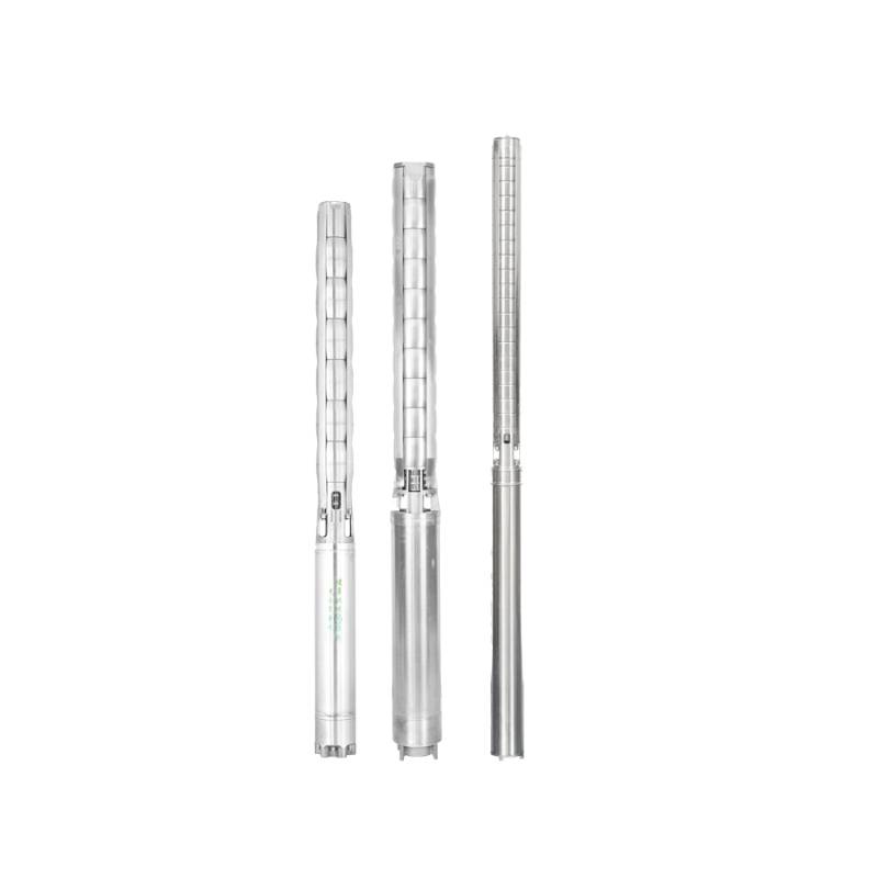
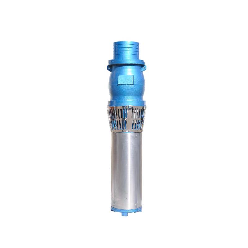
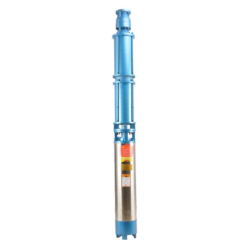
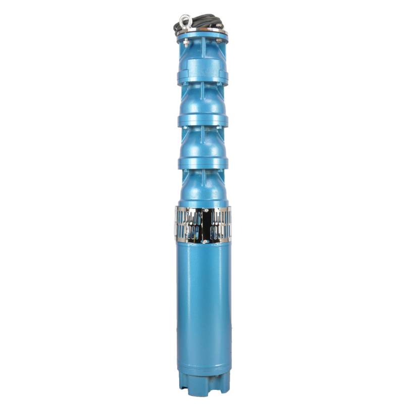
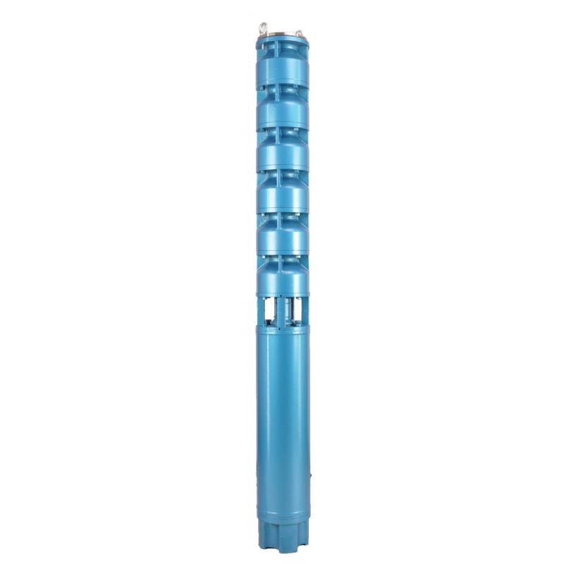
This series of fountain pump is a special fountain pump developed by our factory. The pump motor core is made of high quality cold rolled silicon steel, which makes the pump more efficient, has good magnetic conductivity, and does not produce heat when starting frequently. The two ends of the motor rotor are equipped with alloy copper sleeves with water as lubricant. Stainless steel bushings replace ball bearings, avoiding the problems of easy rust of ball bearings and burnout of motor due to lack of oil and wear. Most suitable for music fountain, all models can be used horizontally.
1. Stromversorgung: dreiphasiger Wechselstrom 380 V (Toleranz +/- 5 %), 50 Hz (Toleranz +/- 1 %).
2, Wasserqualität:
(1) water temperature is not higher than 20 °C;
(2) der Gehalt an festen Verunreinigungen (Massenverhältnis) beträgt nicht mehr als 0,01 %;
(3) PH-Wert (pH) 6,5–8,5;
(4) Der Schwefelwasserstoffgehalt beträgt nicht mehr als 1,5 mg/l;
(5) Der Chloridionengehalt beträgt nicht mehr als 400 mg/l.
3. Der Motor ist eine geschlossene oder mit Wasser gefüllte Nassstruktur. Vor der Verwendung muss der Hohlraum des Tauchmotors mit sauberem Wasser gefüllt sein, um ein falsches Füllen zu verhindern. Ziehen Sie dann die Wassereinspritz- und Luftablassschrauben fest, da die Verwendung sonst nicht zulässig ist.
4. Die Tauchpumpe muss vollständig im Wasser eingetaucht sein, die Tauchtiefe darf 70 m nicht überschreiten und der Abstand zwischen der Tauchpumpe und dem Boden des Brunnens darf nicht weniger als 3 m betragen.
5. Der Brunnenwasserdurchfluss muss der Wasserleistung der Tauchpumpe und dem Dauerbetrieb entsprechen. Die Wasserleistung der Tauchpumpe muss auf das 0,7- bis 1,2-fache des Nenndurchflusses geregelt werden.
6. Der Brunnen sollte gerade sein. Die Tauchpumpe darf nicht verwendet oder entleert werden, sondern nur vertikal verwendet werden.
7. Die Tauchpumpe muss entsprechend den Anforderungen mit dem Kabel und dem externen Überlastschutzgerät ausgestattet sein.
8, die Pumpe ist streng verboten, ohne Wasser Leerlauf-Test-Maschine
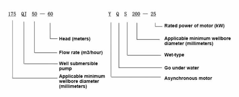
| Modell | Durchfluss (m3/h) | Kopf (M) |
Drehgeschwindigkeit (Wechselpunkt) |
Wasserpumpe(%) | Auslauf Durchmesser (mm) |
Gut anwendbar Durchmesser (mm) |
Bewertet power(KW) |
Bewertet Spannung (V) |
Bewertet Strom (A) |
Motoreffizienz (%) | power factorcosφ | Einheit Radiale Maximalgröße (mm) |
Anmerkung | |||||||||
| 250QJ50-40 | 50 | 40 | 2875 | 72 | 80 | 250über | 9.2 | 380 | 21.7 | 78.5 | 0.82 | 233 | ||||||||||
| 250QJ50-60 | 60 | 13 | 30.1 | 80.0 | 0.82 | |||||||||||||||||
| 250QJ50-80 | 80 | 18.5 | 40.8 | 82.0 | 0.84 | |||||||||||||||||
| 250QJ50-100 | 100 | 22 | 47.9 | 83.0 | 0.84 | |||||||||||||||||
| 250QJ50-120 | 120 | 25 | 53.8 | 84.0 | 0.84 | |||||||||||||||||
| 250QJ50-140 | 140 | 30 | 64.2 | 84.5 | 0.84 | |||||||||||||||||
| 250QJ50-160 | 160 | 37 | 77.8 | 85.0 | 0.85 | |||||||||||||||||
| 250QJ50-200 | 200 | 45 | 94.1 | 85.5 | 0.85 | |||||||||||||||||
| 250QJ50-240 | 240 | 55 | 114.3 | 86.0 | 0.85 | |||||||||||||||||
| 250QJ50-280 | 280 | 63 | 131.0 | 86.0 | 0.85 | |||||||||||||||||
| 250QJ50-320 | 320 | 75 | 152.3 | 87.0 | 0.86 | |||||||||||||||||
| 250QJ50-400 | 400 | 90 | 182.8 | 87.0 | 0.86 | |||||||||||||||||
| 250QJ50-440 | 440 | 100 | 203.1 | 87.0 | 0.86 | |||||||||||||||||
| 250QJ63-40 | 63 | 40 | 2875 | 74 | 80 | 250über | 11 | 380 | 25.8 | 79.0 | 0.82 | 233 | ||||||||||
| 250QJ63-60 | 60 | 18.5 | 40.8 | 82.0 | 0.84 | |||||||||||||||||
| 250QJ63-80 | 80 | 22 | 47.9 | 83.0 | 0.84 | |||||||||||||||||
| 250QJ63-100 | 100 | 30 | 64.2 | 84.5 | 0.84 | |||||||||||||||||
| 250QJ63-120 | 120 | 37 | 77.8 | 85.0 | 0.85 | |||||||||||||||||
| 250QJ63-160 | 160 | 45 | 94.1 | 85.5 | 0.85 | |||||||||||||||||
| 250QJ63-200 | 200 | 55 | 114.3 | 86.0 | 0.85 | |||||||||||||||||
| 250QJ63-220 | 220 | 63 | 131.0 | 86.0 | 0.85 | |||||||||||||||||
| 250QJ63-260 | 260 | 75 | 152.3 | 87.0 | 0.86 | |||||||||||||||||
| 250QJ63-300 | 300 | 90 | 182.8 | 87.0 | 0.86 | |||||||||||||||||
| 250QJ63-360 | 360 | 100 | 203.1 | 87.0 | 0.86 | |||||||||||||||||
| 250QJ80-20 | 80 | 20 | 2875 | 75 | 100 | 250über | 7.5 | 380 | 18.0 | 78.0 | 0.81 | 233 | ||||||||||
| 250QJ80-40 | 40 | 15 | 33.9 | 81.0 | 0.83 | |||||||||||||||||
| 250QJ80-60 | 60 | 22 | 47.9 | 83.0 | 0.84 | |||||||||||||||||
| 250QJ80-80 | 80 | 30 | 64.2 | 84.5 | 0.84 | |||||||||||||||||
| 250QJ80-100 | 100 | 37 | 77.8 | 85.0 | 0.85 | |||||||||||||||||
| 250QJ80-120 | 120 | 45 | 94.1 | 85.5 | 0.85 | |||||||||||||||||
| 250QJ80-160 | 80 | 160 | 2875 | 75 | 100 | 250über | 55 | 380 | 114.3 | 86.0 | 0.85 | 233 | ||||||||||
| 250QJ80-180 | 180 | 63 | 131.0 | 86.0 | 0.85 | |||||||||||||||||
| 250QJ80-200 | 200 | 75 | 152.3 | 87.0 | 0.86 | |||||||||||||||||
| 250QJ80-240 | 240 | 90 | 182.8 | 87.0 | 0.86 | |||||||||||||||||
| 250QJ80-280 | 280 | 100 | 203.1 | 87.0 | 0.86 | |||||||||||||||||
| 250QJ100-18 | 100 | 18 | 2875 | 75 | 100 | 250über | 7.5 | 380 | 18.0 | 78.0 | 0.81 | 233 | ||||||||||
| 250QJ100-36 | 36 | 15 | 33.9 | 81.0 | 0.83 | |||||||||||||||||
| 250QJ100-54 | 54 | 25 | 53.8 | 84.0 | 0.84 | |||||||||||||||||
| 250QJ100-72 | 72 | 30 | 64.2 | 84.5 | 0.84 | |||||||||||||||||
| 250QJ100-90 | 90 | 37 | 77.8 | 85.0 | 0.85 | |||||||||||||||||
| 250QJ100-108 | 108 | 45 | 94.1 | 85.5 | 0.85 | |||||||||||||||||
| 250QJ100-126 | 126 | 55 | 114.3 | 86.0 | 0.85 | |||||||||||||||||
| 250QJ100-144 | 144 | 63 | 131.0 | 86.0 | 0.85 | |||||||||||||||||
| 250QJ100-162 | 162 | 75 | 152.3 | 87.0 | 0.86 | |||||||||||||||||
| 250QJ100-198 | 198 | 90 | 182.8 | 87.0 | 0.86 | |||||||||||||||||
| 250QJ100-216 | 216 | 100 | 203.1 | 87.0 | 0.86 | |||||||||||||||||
| 250QJ125-16 | 125 | 16 | 2875 | 76 | 125 | 250über | 9.2 | 380 | 21.7 | 78.5 | 0.82 | 233 | ||||||||||
| 250QJ125-32 | 32 | 18.5 | 40.8 | 82.0 | 0.84 | |||||||||||||||||
| 250QJ125-48 | 48 | 25 | 53.8 | 84.0 | 0.84 | |||||||||||||||||
| 250QJ125-64 | 64 | 37 | 77.8 | 85.0 | 0.85 | |||||||||||||||||
| 250QJ125-80 | 80 | 45 | 94.1 | 85.5 | 0.85 | |||||||||||||||||
| 250QJ125-96 | 96 | 55 | 114.3 | 86.0 | 0.85 | |||||||||||||||||
| 250QJ125-112 | 112 | 63 | 131.0 | 86.0 | 0.85 | |||||||||||||||||
| 250QJ125-128 | 128 | 75 | 152.3 | 87.0 | 0.86 | |||||||||||||||||
| 250QJ125-160 | 160 | 90 | 182.8 | 87.0 | 0.86 | |||||||||||||||||
| 250QJ125-176 | 176 | 100 | 203.1 | 87.0 | 0.86 | |||||||||||||||||
| 250QJ125-192 | 192 | 110 | 219.6 | 87.5 | 0.87 | |||||||||||||||||
| 250QJ140-15 | 140 | 15 | 2875 | 76 | 125 | 250über | 9.2 | 380 | 21.7 | 78.5 | 0.82 | 233 | ||||||||||
| 250QJ140-30 | 30 | 18.5 | 40.8 | 82.0 | 0.84 | |||||||||||||||||
| 250QJ140-45 | 45 | 30 | 64.2 | 84.5 | 0.84 | |||||||||||||||||
| 250QJ140-60 | 60 | 37 | 77.8 | 85.0 | 0.85 | |||||||||||||||||
| 250QJ140-75 | 45 | 45 | 94.1 | 85.5 | 0.85 | |||||||||||||||||
| 250QJ140-90 | 90 | 55 | 114.3 | 86.0 | 0.85 | |||||||||||||||||
| 250QJ140-105 | 140 | 105 | 2875 | 76 | 125 | 250über | 63 | 380 | 131.0 | 86.0 | 0.85 | 233 | ||||||||||
| 250QJ140-120 | 120 | 75 | 152.3 | 87.0 | 0.86 | |||||||||||||||||
| 250QJ140-150 | 150 | 90 | 182.8 | 87.0 | 0.86 | |||||||||||||||||
| 250QJ140-165 | 165 | 100 | 203.1 | 87.0 | 0.86 | |||||||||||||||||
| 250QJ140-180 | 180 | 110 | 219.6 | 87.5 | 0.87 | |||||||||||||||||
| 250QJ200-20 | 200 | 20 | 2875 | 75 | 150 | 250über | 18.5 | 380 | 40.8 | 82.0 | 0.84 | 233 | ||||||||||
| 250QJ200-40 | 40 | 37 | 77.8 | 85.0 | 0.85 | |||||||||||||||||
| 250QJ200-60 | 60 | 55 | 114.3 | 86.0 | 0.85 | |||||||||||||||||
| 250QJ200-80 | 80 | 75 | 152.3 | 87.0 | 0.86 | |||||||||||||||||
| 250QJ200-100 | 100 | 90 | 182.8 | 87.0 | 0.86 | |||||||||||||||||
| 250QJ200-120 | 120 | 100 | 203.1 | 87.0 | 0.86 | |||||||||||||||||
| 250QJ200-140 | 140 | 125 | 249.5 | 87.5 | 0.87 | |||||||||||||||||
1, well submersible pump for clean water pump, prohibit the new well, pumping sediment and muddy water,
2, well water pump voltage grade of 380/50HZ, the use of other voltage grades of submersible motors need to be customized. The underground cable must use waterproof cable, must be equipped with starting equipment, such as distribution box, start not ready should have commonly used motor comprehensive protection function, such as short circuit overload protection, phase protection, undervoltage protection, grounding protection, idling protection, in case of abnormal conditions, the protection device should be timely action trip.
3, the installation and use of the pump must be reliably grounded, prohibit the push and pull switch when the hands and feet are wet, the installation and maintenance of the pump must be cut off the power supply, the use of the pump place to set up "to prevent electric shock" obvious signs:
4, down the well or before installation, the motor cavity must be filled with distilled water or non-corrosive clean cold boiling water, tighten the / water bolt, the pump on the ground test run, must be to the pump chamber water lubrication rubber bearings, instant start not more than a second, see whether the steering is the same as the steering instructions. When the pump is upright, pay attention to safety, prevent overturning injury.
5. Halten Sie sich strikt an die Bestimmungen für die Pumpenförderung und den Durchflussbereich, um eine zu geringe oder zu hohe Pumpenleistung, Verschleiß des Axiallagers und anderer Teile sowie ein Durchbrennen des Motors durch Überlastung zu verhindern.
6, after the pump down the well, the measurement of the motor to the ground insulation resistance should not be less than 100M, after the start to observe the voltage and current, check the motor winding insulation, whether in line with the requirements; pump storage location temperature if less than freezing point, should be dry the motor cavity water, prevent the motor cavity water ice damage caused by low temperature.
The introduction and structure of this pump product mainly include pump shaft, impeller, shunt shell, rubber bearing, check valve body (optional) and other components. The motor part is mainly composed of base, pressure regulating diaphragm, thrust bearing, thrust plate, lower guide bearing seat, stator, rotor, upper guide bearing seat, sand ring, water inlet section, lead cable and other components. The main characteristics of this pump product include the use of water-cooled wet submersible three-phase asynchronous motor, the motor cavity is filled with clean water to cool the motor and lubricate the bearing, the pressure regulating diaphragm at the bottom is used to adjust the expansion and contraction pressure difference of the internal water caused by the change of the temperature rise of the motor. In order to prevent the sand particles in the well water from entering the motor, two oil seals are installed on the upper end of the motor shaft extension, and the sand ring is installed to form a sand prevention structure. In order to avoid the pump shaft jumping at startup, the pump shaft and the motor shaft are connected together through the coupling, and the thrust bearing is installed at the lower part of the motor. The motor and pump bearing lubrication adopts water lubrication. The stator winding of the motor adopts high quality submersible motor winding, with high insulation performance. The pump adopts computer CAD design, simple structure and superior technical performance.

(1)Vorbereitung vor der Installation:
1. Prüfen Sie, ob die Tauchpumpe die in der Anleitung angegebenen Einsatzbedingungen und den Einsatzbereich erfüllt.
2. Messen Sie mit einem schweren Gegenstand, dessen Durchmesser dem maximalen Außendurchmesser der Tauchpumpe entspricht, ob der Innendurchmesser des Bohrlochs für die Tauchpumpe geeignet ist, und messen Sie, ob die Bohrlochtiefe den Installationsanforderungen entspricht.
3. Überprüfen Sie, ob das Bohrloch sauber ist und ob das Brunnenwasser trübe ist. Verwenden Sie niemals eine Tauchpumpe, um Schlamm und Sandwasser aus der Brunnenpumpe zu waschen, um vorzeitige Schäden an der Tauchpumpe zu vermeiden.
4. Prüfen Sie, ob die Position der Schweißkopf-Montageklemme geeignet ist und ob sie der Qualität der gesamten Einheit standhält
5. Überprüfen Sie, ob die Komponenten der Tauchpumpe vollständig sind und gemäß dem Montageplan im Handbuch ordnungsgemäß installiert wurden. Entfernen Sie das Filtersieb und drehen Sie die Kupplung, um zu sehen, ob sie sich flexibel dreht.
6. Die Wasserschraube abschrauben und den Motorhohlraum mit sauberem, nicht korrosivem Wasser füllen (Hinweis: unbedingt auffüllen), dann die Wasserschraube festziehen. Nach 12 Stunden Wassereinspritzung sollte der Isolationswiderstand des Motors bei Messung mit einem 500-V-Schütteltisch nicht weniger als 150 MQ betragen.
7. Cable joint, cut off a 120mm rubber sleeve from one end of the outgoing cable and the matching cable with an electrician's knifethen stagger the length of the three core wires in a stepped shape, peel off a 20mm copper core, scrape of the oxide layer on theoutside of the copper wire with a knife or sand cloth, and insert the two connected wire ends in palirs.After tying the layer tightly with fine copper wire, solder it thoroughly and firmly, and sand of any. burrs on the surface. Then, forthe three joints, use polyvester insulation tape to wrap them in a semi stacked manner for three lavers. Wrap the two ends of thewrapping layer tightywith nyion thread,and then use a semi stacked method to wrap the tape for three layers. Wrap the outellayer with high-pressure insulation tape for three layers. Finally, fold the threestrands together and repeatedly wrap them for fivelayers with high-pressure tape. Each layer must be tightly tied, and the interlayer joints must be tight and fimm to prevent water frompenetrating and damaging the insulation, After wrapping, soak in water at room temperature of 20 ’c for 12 hours, and measurethe insulation resistance with a shaking table, which should not be less than 100M Ω
Das beigefügte Diagramm zur Kabelverlegung sieht wie folgt aus: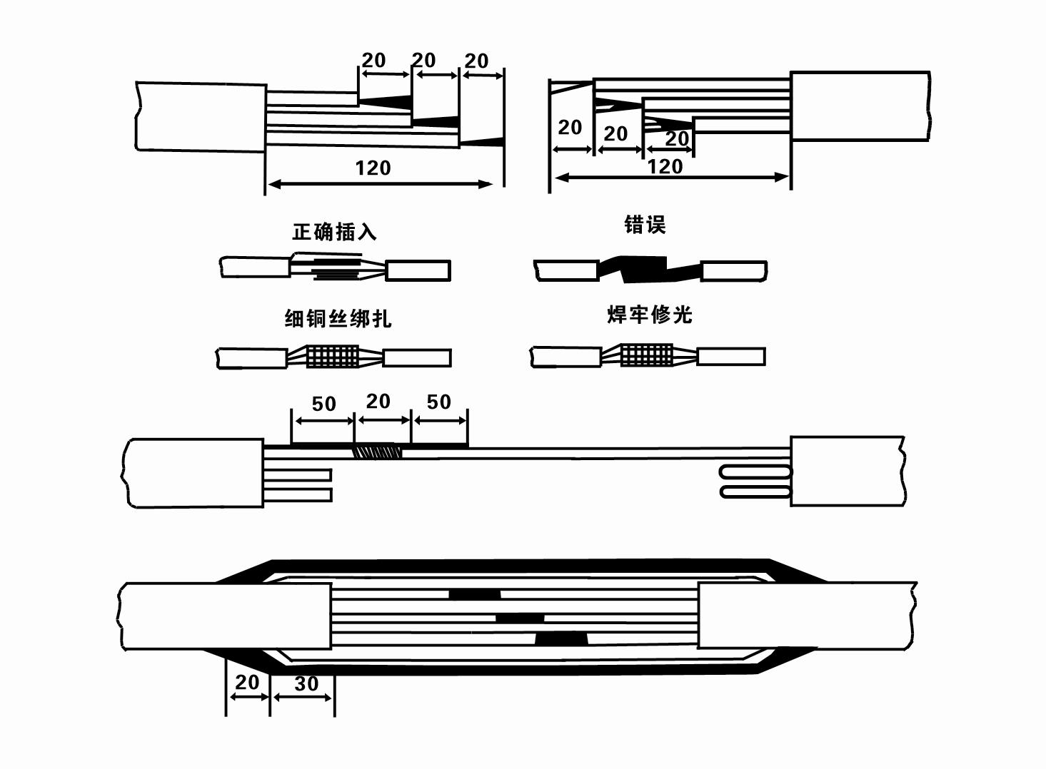
8. Prüfen Sie mit einem Multimeter, ob die Drehstromleitungen angeschlossen sind und der Gleichstromwiderstand etwa ausgeglichen ist.
9. Überprüfen Sie, ob der Stromkreis und die Transformatorkapazität überlastet sind, und schließen Sie dann den Überlastschutzschalter oder die Startvorrichtung an. Siehe Tabelle 2 für bestimmte Modelle. Gießen Sie dann einen Eimer Wasser aus dem Wasserpumpenauslass in die Wasserpumpe, um die Gummilager in der Pumpe zu schmieren, und stellen Sie die Tauchpumpe dann aufrecht und stabil auf. Starten Sie (nicht länger als eine Sekunde) und prüfen Sie, ob die Lenkrichtung mit dem Lenkzeichen übereinstimmt. Wenn nicht, tauschen Sie zwei beliebige Anschlüsse des Dreiphasenkabels aus. Installieren Sie dann den Filter und bereiten Sie sich darauf vor, in den Brunnen zu gehen. Bei Verwendung in besonderen Fällen (z. B. Gräben, Flüssen, Teichen, Teichen usw.) muss die Elektropumpe zuverlässig geerdet sein.
(2)Installationsausrüstung und Werkzeuge:
1. Ein Paar Hebeketten für mehr als zwei Tonnen.
2. Ein Stativ mit einer vertikalen Höhe von mindestens vier Metern.
3. Zwei Hängeseile (Drahtseile), die ein Gewicht von mehr als einer Tonne tragen können (können das Gewicht eines kompletten Wasserpumpensatzes tragen).
4. Installieren Sie zwei Paar Klammern (Schienen).
5. Schraubenschlüssel, Hämmer, Schraubendreher, elektrische Werkzeuge und Instrumente usw.
(3)Installation der elektrischen Pumpe:
1. Das Installationsdiagramm der Tauchelektropumpe ist in Abbildung 2 dargestellt. Die spezifischen Installationsabmessungen sind in Tabelle 3 „Liste der Installationsabmessungen der Tauchelektropumpe“ aufgeführt.
2. Tauchpumpen mit einer Förderhöhe von weniger als 30 Metern können mit Schläuchen und Drahtseilen oder anderen Hanfseilen, die das gesamte Gewicht der gesamten Maschine, der Wasserleitungen und des Wassers in den Rohren tragen können, direkt in den Brunnen gehoben werden.
3. Pumpen mit einer Förderhöhe von mehr als 30 Metern verwenden Stahlrohre und die Installationsreihenfolge ist wie folgt:
①Befestigen Sie das obere Ende des Wasserpumpenteils mit einer Klemme (Motor und Wasserpumpe sind zu diesem Zeitpunkt bereits verbunden), heben Sie es mit einer Hängekette an und binden Sie es langsam in den Brunnen, bis die Klemme auf den Brunnenkopf aufgesetzt und die Hängekette entfernt ist.
② Verwenden Sie ein weiteres Paar Klemmen, um ein Rohr festzuklemmen, heben Sie es mit einer Hängekette 15 cm vom Flansch entfernt an und senken Sie es langsam ab. Legen Sie zwischen Rohrflansch und Pumpenflansch das Gummipolster an und ziehen Sie Rohr und Pumpe mit Schrauben, Muttern und Federscheiben gleichmäßig fest.
③ Heben Sie die Tauchpumpe leicht an, entfernen Sie die Klemme am oberen Ende der Wasserpumpe, binden Sie das Kabel mit einem Kunststoffband fest an die Wasserleitung und binden Sie es langsam nach unten, bis die Klemme am Bohrlochkopf platziert ist.
④Verwenden Sie die gleiche Methode, um alle Wasserleitungen an den Brunnen anzuschließen.
⑤Nachdem das Ausgangskabel mit dem Steuerschalter verbunden ist, wird es an die dreiphasige Stromversorgung angeschlossen.
(4)Bei der Installation zu beachtende Punkte:
1. Wenn während des Pumpvorgangs ein Blockierungsphänomen festgestellt wird, drehen oder ziehen Sie am Wasserrohr, um die Blockierungsstelle zu beheben. Wenn verschiedene Maßnahmen immer noch nicht funktionieren, drücken Sie die Pumpe bitte nicht mit Gewalt nach unten, um Schäden an der Tauchpumpe und dem Brunnen zu vermeiden.
2. Während der Installation sollte am Flansch jedes Rohrs eine Gummiunterlage platziert und gleichmäßig festgezogen werden.
3. Wenn die Wasserpumpe in den Brunnen abgesenkt wird, sollte sie in der Mitte des Brunnenrohrs platziert werden, um zu verhindern, dass die Pumpe längere Zeit gegen die Brunnenwand läuft, was zu Vibrationen der Pumpe und zum Fegen und Verbrennen des Motors führen kann.
4. Bestimmen Sie die Tiefe der Wasserpumpe bis zum Boden des Brunnens entsprechend den fließenden Sand- und Schlickbedingungen des Brunnens. Vergraben Sie die Pumpe nicht im Schlamm. Der Abstand von der Wasserpumpe bis zum Boden des Brunnens beträgt im Allgemeinen nicht weniger als 3 Meter (siehe Abbildung 2).
5. Die Wassereintrittstiefe der Wasserpumpe sollte vom dynamischen Wasserstand bis zum Wassereinlassknoten nicht weniger als 1–1,5 Meter betragen (siehe Abbildung 2). Andernfalls können die Lager der Wasserpumpe leicht beschädigt werden.
6. Die Förderhöhe der Wasserpumpe darf nicht zu niedrig sein. Andernfalls muss an der Wasserleitung am Bohrlochkopf ein Absperrschieber installiert werden, um den Pumpendurchfluss am Nenndurchflusspunkt zu steuern und zu verhindern, dass der Motor aufgrund großer Durchflussraten überlastet wird und durchbrennt.
7. Wenn die Wasserpumpe läuft, sollte die Wasserabgabe kontinuierlich und gleichmäßig erfolgen, der Strom sollte stabil sein (unter Nennbetriebsbedingungen im Allgemeinen nicht mehr als 10 % des Nennstroms) und es sollten keine Vibrationen oder Geräusche auftreten. Bei Anomalien sollte die Maschine angehalten werden, um die Ursache herauszufinden und zu beseitigen.
8. Achten Sie bei der Installation auf die Einstellung des Motorerdungskabels (siehe Abbildung 2). Wenn es sich bei der Wasserleitung um ein Stahlrohr handelt, führen Sie es von der Bohrlochkopfklemme aus; wenn es sich bei der Wasserleitung um ein Kunststoffrohr handelt, führen Sie es von der Erdungsmarkierung der Elektropumpe aus.
After the installation of the underwater pump, the insulation resistance and three-phase continuity of the switch face should be rechecked, and the connection between the instrument and the start device should be checked for any errors. If there is no problem, you can start to test the machine. After the start, observe whether the indication readings of each instrument are correct. If the rated voltage and current specified on the nameplate are exceeded, observe whether the pump has noise or vibration. If everything is normal, it can be put into operation. After the first operation of the pump for four hours, the motor should be shut down and tested for thermal insulation resistance quickly. Its value should not be less than 0.5 megaohm. After stopping the pump, it should be restarted after an interval of five minutes to prevent the water column in the pipeline from completely reversing and causing the motor to burn out due to excessive current. After the pump is put into normal operation, in order to prolong its service life, it is necessary to check regularly whether the supply voltage, running current and insulation resistance are normal. If the following conditions are found, the machine should be shut down immediately to eliminate the fault: the current exceeds 20% under rated working conditions; the dynamic water level drops to the inlet section, resulting in intermittent drainage; the underwater pump becomes violently vibrating or making noise; the supply voltage is lower than 340 volts; a fuse is blown out; the water pipe is damaged; the motor's thermal insulation resistance to the earth is less than 0.5 megaohm. The sequence of disassembly is: untie the cable fastening, remove the pipeline part, remove the line protection plate, screw down the water discharge bolt and discharge all the water in the motor chamber, remove the filter and loosen the coupling fixing screw of the motor shaft. The sequence of disassembly of the pump is: (see Figure 1) inlet section, impeller, guide housing, impeller, check the valve body. When removing the impeller, use special tools to loosen the taper sleeve of the impeller. Avoid bending the pump shaft and damaging the components throughout the process. The disassembly process of the motor is: (see Figure 1) put the motor on the platform, and remove the bolts, base, shaft head lock nut, thrust plate, key, lower guide plate (transverse bolt), bearing seat, screw knife seat from the bottom of the motor in order (take care not to damage the winding), and finally remove the connecting part and the upper guide bearing seat. Before assembling the unit, the rust and dirt of each part should be cleaned, and the sealant should be applied to each mating surface and fastener, and then assembled in reverse order of disassembly (the movement of the motor shaft after assembly is about one millimeter). After assembly, the coupling should be rotated flexibly and put on the filter for test. Once a year, or if less than a year of operation but has been immersed for two years, the underwater electric pump must be disassembled for maintenance in accordance with Article 5 and replace worn parts to ensure the normal operation and durability of the pump.
1. Lassen Sie das Wasser im Motorraum ab (besonders im Winter, um ein Einfrieren des Motors zu verhindern) und binden Sie das Kabel gut fest.
2, store in an indoor room without corrosive substances and gases, with a temperature below 40 °C.
3. Bei längerem Gebrauch sollte auf den Rostschutz der Tauchpumpen geachtet werden.
- Laufrad
- Wellenschutzhülse
- Wellenschutzhülse aus Gummi
-
Siegelring
01 Wasserentnahme aus einem tiefen Brunnen
02 Hochwasserversorgung
03 Bergwasserversorgung
04 Turm Wasser
05 Landwirtschaftliche Bewässerung
06 Gartenbewässerung
07 Flusswasserentnahme
08 Brauchwasser

