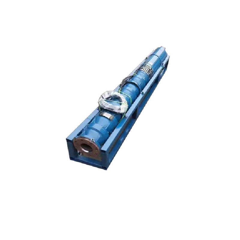
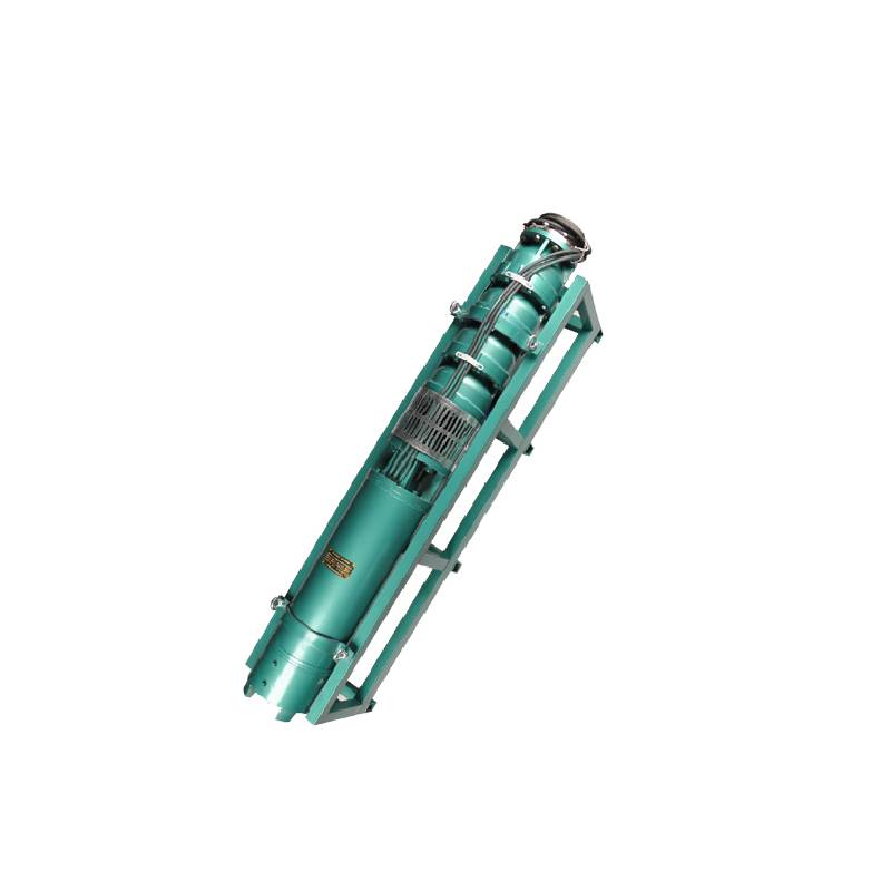
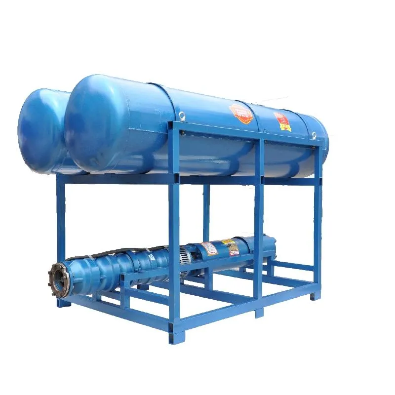
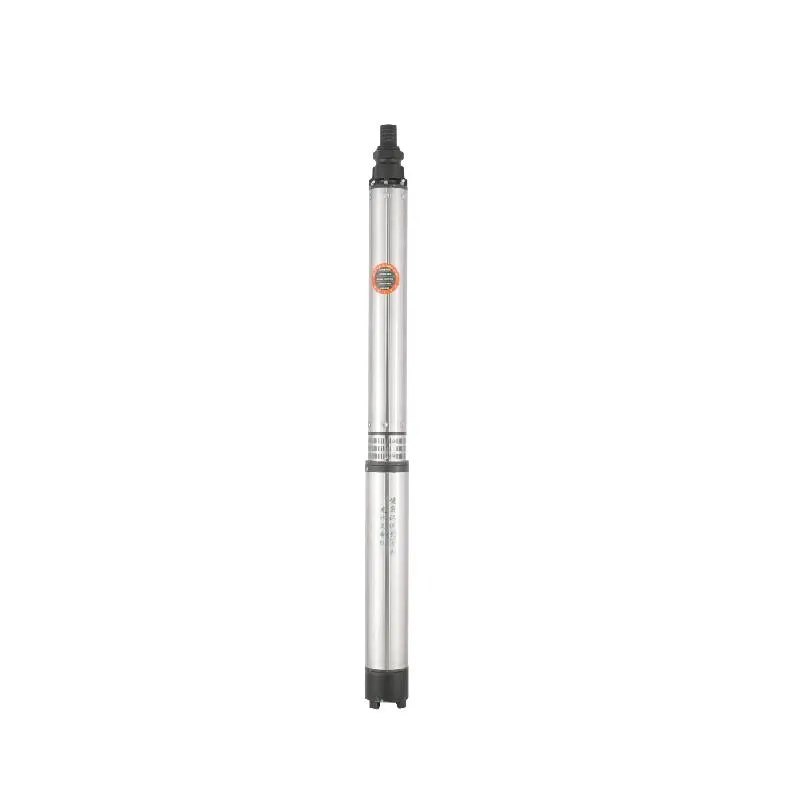
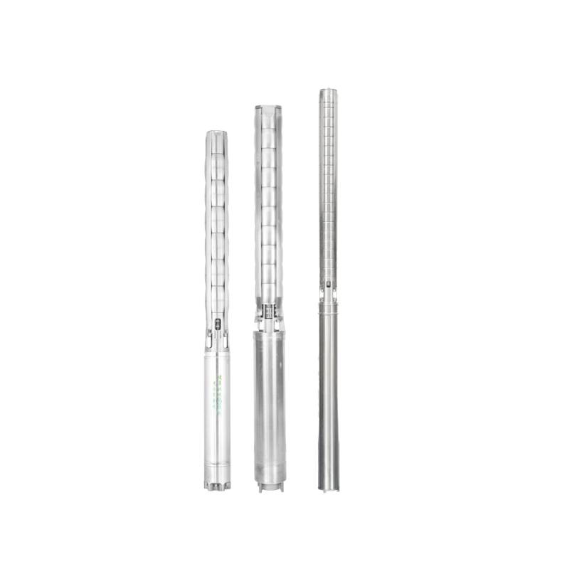
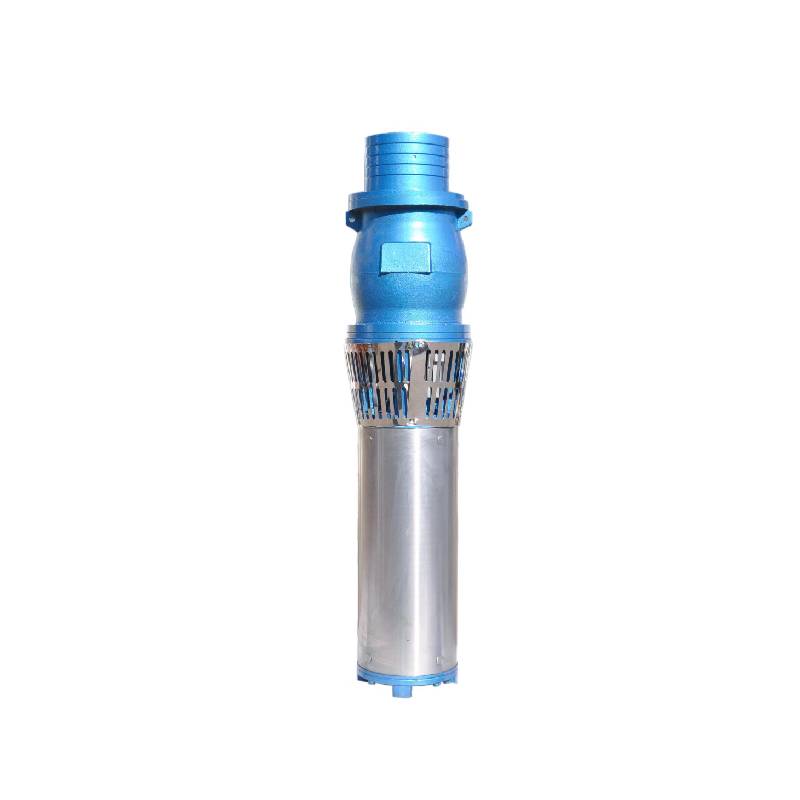
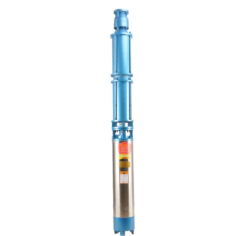
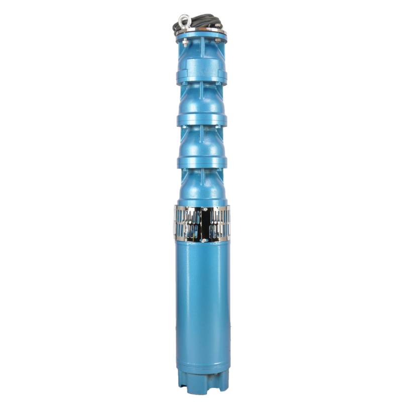
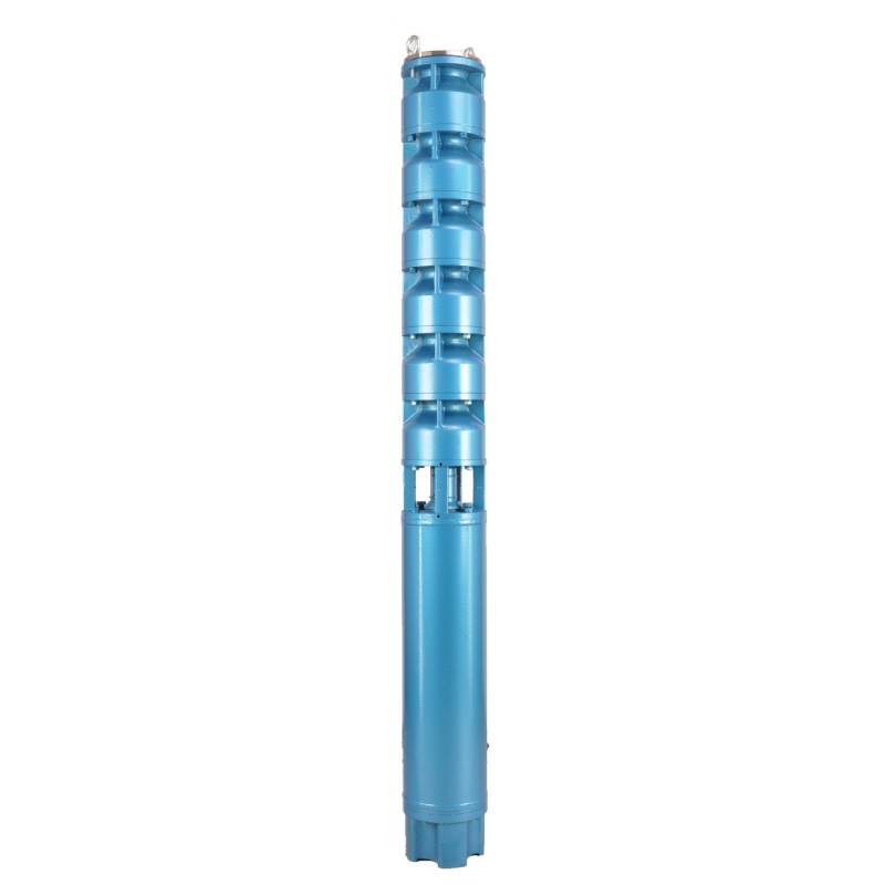
This series of fountain pump is a special fountain pump developed by our factory. The pump motor core is made of high quality cold rolled silicon steel, which makes the pump more efficient, has good magnetic conductivity, and does not produce heat when starting frequently. The two ends of the motor rotor are equipped with alloy copper sleeves with water as lubricant. Stainless steel bushings replace ball bearings, avoiding the problems of easy rust of ball bearings and burnout of motor due to lack of oil and wear. Most suitable for music fountain, all models can be used horizontally.
1, Stroumversuergung: Dräi-Phase AC 380V (Toleranz +/- 5%), 50HZ (Toleranz +/- 1%).
2, Waasserqualitéit:
(1) water temperature is not higher than 20 °C;
(2) fest Gëftstoffer Inhalt (Mass Verhältnis) ass net méi wéi 0,01%;
(3) PH Wäert (pH) 6,5-8,5;
(4) Waasserstoff sulfide Inhalt ass net méi grouss wéi 1.5mg / L;
(5) Chloridiongehalt ass net méi wéi 400mg/L.
3, de Motor ass zou oder Waasser-gefëllt naass Struktur, virum Gebrauch der submersible Motor Kavitéit muss voller propper Waasser sinn, falsch voll ze verhënneren, an dann d'Waasser Sprëtz, Loft Fräisetzung Bolzen zouzedrécken, soss net erlaabt ze benotzen
4, Tauchpompel muss komplett am Waasser ënnergeet ginn, d'Tauchdéift ass net méi wéi 70m, de Buedem vun der Tauchpompel vun der Brunn ass net manner wéi 3m.
5, soll de Well Waasser Flux fäeg sinn der submersible Pompel Waasser Wasserstoff a kontinuéierlech Operatioun ze treffen, der submersible Pompel Waasser Wasserstoff soll op 0,7 - 1,2 Mol de bewäert Flux kontrolléiert ginn.
6, de Brunn soll riicht sinn, d'Tauchtpompel kann net benotzt oder gedumpt ginn, nëmme vertikal benotzt.
7, muss d'Tauchtpompel mat dem Kabel entspriechend den Ufuerderunge passen, an dem externen Iwwerlaaschtschutzapparat.
8, ass d'Pompel streng verbueden ouni Waasser No-Laascht Test Maschinn
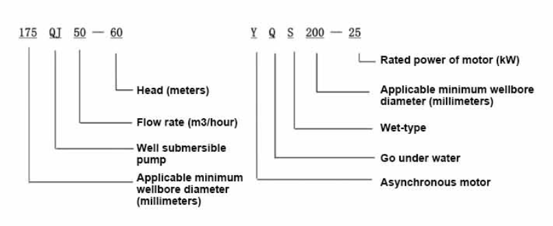
| Modell | Flow (m3/h) | Kapp (m) |
Rotatiounsgeschwindegkeet (Ännerung / Punkt) |
Waasserpompel (%) | Outlet Duerchmiesser (mm) |
Gutt applicabel Duerchmiesser (mm) |
Bewäert power(KW) |
Bewäert Spannung (V) |
Bewäert aktuell (A) |
Motoreffizienz (%) | power factorcosφ | Eenheet Radial Maximum Gréisst (mm) |
Remarque | |||||||||
| 250QJ50-40 | 50 | 40 | 2875 | 72 | 80 | 250uewen | 9.2 | 380 | 21.7 | 78.5 | 0.82 | 233 | ||||||||||
| 250QJ50-60 | 60 | 13 | 30.1 | 80.0 | 0.82 | |||||||||||||||||
| 250QJ50-80 | 80 | 18.5 | 40.8 | 82.0 | 0.84 | |||||||||||||||||
| 250QJ50-100 | 100 | 22 | 47.9 | 83.0 | 0.84 | |||||||||||||||||
| 250QJ50-120 | 120 | 25 | 53.8 | 84.0 | 0.84 | |||||||||||||||||
| 250QJ50-140 | 140 | 30 | 64.2 | 84.5 | 0.84 | |||||||||||||||||
| 250QJ50-160 | 160 | 37 | 77.8 | 85.0 | 0.85 | |||||||||||||||||
| 250QJ50-200 | 200 | 45 | 94.1 | 85.5 | 0.85 | |||||||||||||||||
| 250QJ50-240 | 240 | 55 | 114.3 | 86.0 | 0.85 | |||||||||||||||||
| 250QJ50-280 | 280 | 63 | 131.0 | 86.0 | 0.85 | |||||||||||||||||
| 250QJ50-320 | 320 | 75 | 152.3 | 87.0 | 0.86 | |||||||||||||||||
| 250QJ50-400 | 400 | 90 | 182.8 | 87.0 | 0.86 | |||||||||||||||||
| 250QJ50-440 | 440 | 100 | 203.1 | 87.0 | 0.86 | |||||||||||||||||
| 250QJ63-40 | 63 | 40 | 2875 | 74 | 80 | 250uewen | 11 | 380 | 25.8 | 79.0 | 0.82 | 233 | ||||||||||
| 250QJ63-60 | 60 | 18.5 | 40.8 | 82.0 | 0.84 | |||||||||||||||||
| 250QJ63-80 | 80 | 22 | 47.9 | 83.0 | 0.84 | |||||||||||||||||
| 250QJ63-100 | 100 | 30 | 64.2 | 84.5 | 0.84 | |||||||||||||||||
| 250QJ63-120 | 120 | 37 | 77.8 | 85.0 | 0.85 | |||||||||||||||||
| 250QJ63-160 | 160 | 45 | 94.1 | 85.5 | 0.85 | |||||||||||||||||
| 250QJ63-200 | 200 | 55 | 114.3 | 86.0 | 0.85 | |||||||||||||||||
| 250QJ63-220 | 220 | 63 | 131.0 | 86.0 | 0.85 | |||||||||||||||||
| 250QJ63-260 | 260 | 75 | 152.3 | 87.0 | 0.86 | |||||||||||||||||
| 250QJ63-300 | 300 | 90 | 182.8 | 87.0 | 0.86 | |||||||||||||||||
| 250QJ63-360 | 360 | 100 | 203.1 | 87.0 | 0.86 | |||||||||||||||||
| 250QJ80-20 | 80 | 20 | 2875 | 75 | 100 | 250uewen | 7.5 | 380 | 18.0 | 78.0 | 0.81 | 233 | ||||||||||
| 250QJ80-40 | 40 | 15 | 33.9 | 81.0 | 0.83 | |||||||||||||||||
| 250QJ80-60 | 60 | 22 | 47.9 | 83.0 | 0.84 | |||||||||||||||||
| 250QJ80-80 | 80 | 30 | 64.2 | 84.5 | 0.84 | |||||||||||||||||
| 250QJ80-100 | 100 | 37 | 77.8 | 85.0 | 0.85 | |||||||||||||||||
| 250QJ80-120 | 120 | 45 | 94.1 | 85.5 | 0.85 | |||||||||||||||||
| 250QJ80-160 | 80 | 160 | 2875 | 75 | 100 | 250uewen | 55 | 380 | 114.3 | 86.0 | 0.85 | 233 | ||||||||||
| 250QJ80-180 | 180 | 63 | 131.0 | 86.0 | 0.85 | |||||||||||||||||
| 250QJ80-200 | 200 | 75 | 152.3 | 87.0 | 0.86 | |||||||||||||||||
| 250QJ80-240 | 240 | 90 | 182.8 | 87.0 | 0.86 | |||||||||||||||||
| 250QJ80-280 | 280 | 100 | 203.1 | 87.0 | 0.86 | |||||||||||||||||
| 250QJ100-18 | 100 | 18 | 2875 | 75 | 100 | 250uewen | 7.5 | 380 | 18.0 | 78.0 | 0.81 | 233 | ||||||||||
| 250QJ100-36 | 36 | 15 | 33.9 | 81.0 | 0.83 | |||||||||||||||||
| 250QJ100-54 | 54 | 25 | 53.8 | 84.0 | 0.84 | |||||||||||||||||
| 250QJ100-72 | 72 | 30 | 64.2 | 84.5 | 0.84 | |||||||||||||||||
| 250QJ100-90 | 90 | 37 | 77.8 | 85.0 | 0.85 | |||||||||||||||||
| 250QJ100-108 | 108 | 45 | 94.1 | 85.5 | 0.85 | |||||||||||||||||
| 250QJ100-126 | 126 | 55 | 114.3 | 86.0 | 0.85 | |||||||||||||||||
| 250QJ100-144 | 144 | 63 | 131.0 | 86.0 | 0.85 | |||||||||||||||||
| 250QJ100-162 | 162 | 75 | 152.3 | 87.0 | 0.86 | |||||||||||||||||
| 250QJ100-198 | 198 | 90 | 182.8 | 87.0 | 0.86 | |||||||||||||||||
| 250QJ100-216 | 216 | 100 | 203.1 | 87.0 | 0.86 | |||||||||||||||||
| 250QJ125-16 | 125 | 16 | 2875 | 76 | 125 | 250uewen | 9.2 | 380 | 21.7 | 78.5 | 0.82 | 233 | ||||||||||
| 250QJ125-32 | 32 | 18.5 | 40.8 | 82.0 | 0.84 | |||||||||||||||||
| 250QJ125-48 | 48 | 25 | 53.8 | 84.0 | 0.84 | |||||||||||||||||
| 250QJ125-64 | 64 | 37 | 77.8 | 85.0 | 0.85 | |||||||||||||||||
| 250QJ125-80 | 80 | 45 | 94.1 | 85.5 | 0.85 | |||||||||||||||||
| 250QJ125-96 | 96 | 55 | 114.3 | 86.0 | 0.85 | |||||||||||||||||
| 250QJ125-112 | 112 | 63 | 131.0 | 86.0 | 0.85 | |||||||||||||||||
| 250QJ125-128 | 128 | 75 | 152.3 | 87.0 | 0.86 | |||||||||||||||||
| 250QJ125-160 | 160 | 90 | 182.8 | 87.0 | 0.86 | |||||||||||||||||
| 250QJ125-176 | 176 | 100 | 203.1 | 87.0 | 0.86 | |||||||||||||||||
| 250QJ125-192 | 192 | 110 | 219.6 | 87.5 | 0.87 | |||||||||||||||||
| 250QJ140-15 | 140 | 15 | 2875 | 76 | 125 | 250uewen | 9.2 | 380 | 21.7 | 78.5 | 0.82 | 233 | ||||||||||
| 250QJ140-30 | 30 | 18.5 | 40.8 | 82.0 | 0.84 | |||||||||||||||||
| 250QJ140-45 | 45 | 30 | 64.2 | 84.5 | 0.84 | |||||||||||||||||
| 250QJ140-60 | 60 | 37 | 77.8 | 85.0 | 0.85 | |||||||||||||||||
| 250QJ140-75 | 45 | 45 | 94.1 | 85.5 | 0.85 | |||||||||||||||||
| 250QJ140-90 | 90 | 55 | 114.3 | 86.0 | 0.85 | |||||||||||||||||
| 250QJ140-105 | 140 | 105 | 2875 | 76 | 125 | 250uewen | 63 | 380 | 131.0 | 86.0 | 0.85 | 233 | ||||||||||
| 250QJ140-120 | 120 | 75 | 152.3 | 87.0 | 0.86 | |||||||||||||||||
| 250QJ140-150 | 150 | 90 | 182.8 | 87.0 | 0.86 | |||||||||||||||||
| 250QJ140-165 | 165 | 100 | 203.1 | 87.0 | 0.86 | |||||||||||||||||
| 250QJ140-180 | 180 | 110 | 219.6 | 87.5 | 0.87 | |||||||||||||||||
| 250QJ200-20 | 200 | 20 | 2875 | 75 | 150 | 250uewen | 18.5 | 380 | 40.8 | 82.0 | 0.84 | 233 | ||||||||||
| 250QJ200-40 | 40 | 37 | 77.8 | 85.0 | 0.85 | |||||||||||||||||
| 250QJ200-60 | 60 | 55 | 114.3 | 86.0 | 0.85 | |||||||||||||||||
| 250QJ200-80 | 80 | 75 | 152.3 | 87.0 | 0.86 | |||||||||||||||||
| 250QJ200-100 | 100 | 90 | 182.8 | 87.0 | 0.86 | |||||||||||||||||
| 250QJ200-120 | 120 | 100 | 203.1 | 87.0 | 0.86 | |||||||||||||||||
| 250QJ200-140 | 140 | 125 | 249.5 | 87.5 | 0.87 | |||||||||||||||||
1, well submersible pump for clean water pump, prohibit the new well, pumping sediment and muddy water,
2, well water pump voltage grade of 380/50HZ, the use of other voltage grades of submersible motors need to be customized. The underground cable must use waterproof cable, must be equipped with starting equipment, such as distribution box, start not ready should have commonly used motor comprehensive protection function, such as short circuit overload protection, phase protection, undervoltage protection, grounding protection, idling protection, in case of abnormal conditions, the protection device should be timely action trip.
3, the installation and use of the pump must be reliably grounded, prohibit the push and pull switch when the hands and feet are wet, the installation and maintenance of the pump must be cut off the power supply, the use of the pump place to set up "to prevent electric shock" obvious signs:
4, down the well or before installation, the motor cavity must be filled with distilled water or non-corrosive clean cold boiling water, tighten the / water bolt, the pump on the ground test run, must be to the pump chamber water lubrication rubber bearings, instant start not more than a second, see whether the steering is the same as the steering instructions. When the pump is upright, pay attention to safety, prevent overturning injury.
5, strikt no de Bestëmmunge vun der Pompel Lift, Flux Gamme vun benotzen, niddereg Flux oder héich Lift Pompel Kraaft ze verhënneren, de Schub Lager an aner Deeler vun der zouzedrécken, de Motor iwwerlaascht verbrannt
6, after the pump down the well, the measurement of the motor to the ground insulation resistance should not be less than 100M, after the start to observe the voltage and current, check the motor winding insulation, whether in line with the requirements; pump storage location temperature if less than freezing point, should be dry the motor cavity water, prevent the motor cavity water ice damage caused by low temperature.
The introduction and structure of this pump product mainly include pump shaft, impeller, shunt shell, rubber bearing, check valve body (optional) and other components. The motor part is mainly composed of base, pressure regulating diaphragm, thrust bearing, thrust plate, lower guide bearing seat, stator, rotor, upper guide bearing seat, sand ring, water inlet section, lead cable and other components. The main characteristics of this pump product include the use of water-cooled wet submersible three-phase asynchronous motor, the motor cavity is filled with clean water to cool the motor and lubricate the bearing, the pressure regulating diaphragm at the bottom is used to adjust the expansion and contraction pressure difference of the internal water caused by the change of the temperature rise of the motor. In order to prevent the sand particles in the well water from entering the motor, two oil seals are installed on the upper end of the motor shaft extension, and the sand ring is installed to form a sand prevention structure. In order to avoid the pump shaft jumping at startup, the pump shaft and the motor shaft are connected together through the coupling, and the thrust bearing is installed at the lower part of the motor. The motor and pump bearing lubrication adopts water lubrication. The stator winding of the motor adopts high quality submersible motor winding, with high insulation performance. The pump adopts computer CAD design, simple structure and superior technical performance.

(1) Virbereedung virun der Installatioun:
1. Iwwerpréift ob d'Tauchtpompel d'Benotzungsbedéngungen an den Ëmfang entsprécht, déi am Handbuch spezifizéiert sinn.
2. Benotzt e schwéieren Objet mat engem Duerchmiesser gläich wéi de maximalen äusseren Duerchmiesser vun der Tauchpompel, moosst ob den Inneldiameter vun der Wellbore d'Tauchpompel passt, a moosst ob d'Wueldéift d'Installatiounsufuerderunge entsprécht.
3. Iwwerpréift ob de Wellbore propper ass an ob d'Wuelwasser türbid ass. Benotzt ni eng submersibel elektresch Pompel fir de Welor Pompel Schlamm a Sand Waasser ze wäschen fir virzäitegen Schued un der Tauchtpompel ze vermeiden.
4. Iwwerpréift ob d'Positioun vun der Wellhead Installatiounsklem gëeegent ass an ob et d'Qualitéit vun der ganzer Eenheet widderstoen kann
5. Iwwerpréift ob d'Tauchpompelkomponenten komplett sinn a richteg installéiert sinn no dem Montagediagramm am Handbuch De Filterbildschierm ewechhuelen an d'Kupplung rotéieren fir ze kucken ob se flexibel rotéiert
6. Schrauwen d'Waasserschrauwen un a fëllt d'Motorhuelraum mat propperem, net ätzendem Waasser (Notiz. Gitt sécher datt Dir se fillt), da dréit d'Waasserschraube fest. No 12 Stonnen Waasserinjektioun, däerf d'Isolatiounsresistenz vum Motor net manner wéi 150M Q sinn wann se mat engem 500V Schüttdësch gemooss ginn.
7. Cable joint, cut off a 120mm rubber sleeve from one end of the outgoing cable and the matching cable with an electrician's knifethen stagger the length of the three core wires in a stepped shape, peel off a 20mm copper core, scrape of the oxide layer on theoutside of the copper wire with a knife or sand cloth, and insert the two connected wire ends in palirs.After tying the layer tightly with fine copper wire, solder it thoroughly and firmly, and sand of any. burrs on the surface. Then, forthe three joints, use polyvester insulation tape to wrap them in a semi stacked manner for three lavers. Wrap the two ends of thewrapping layer tightywith nyion thread,and then use a semi stacked method to wrap the tape for three layers. Wrap the outellayer with high-pressure insulation tape for three layers. Finally, fold the threestrands together and repeatedly wrap them for fivelayers with high-pressure tape. Each layer must be tightly tied, and the interlayer joints must be tight and fimm to prevent water frompenetrating and damaging the insulation, After wrapping, soak in water at room temperature of 20 ’c for 12 hours, and measurethe insulation resistance with a shaking table, which should not be less than 100M Ω
Dat befestegt Kabelverdrahtungsdiagramm ass wéi follegt: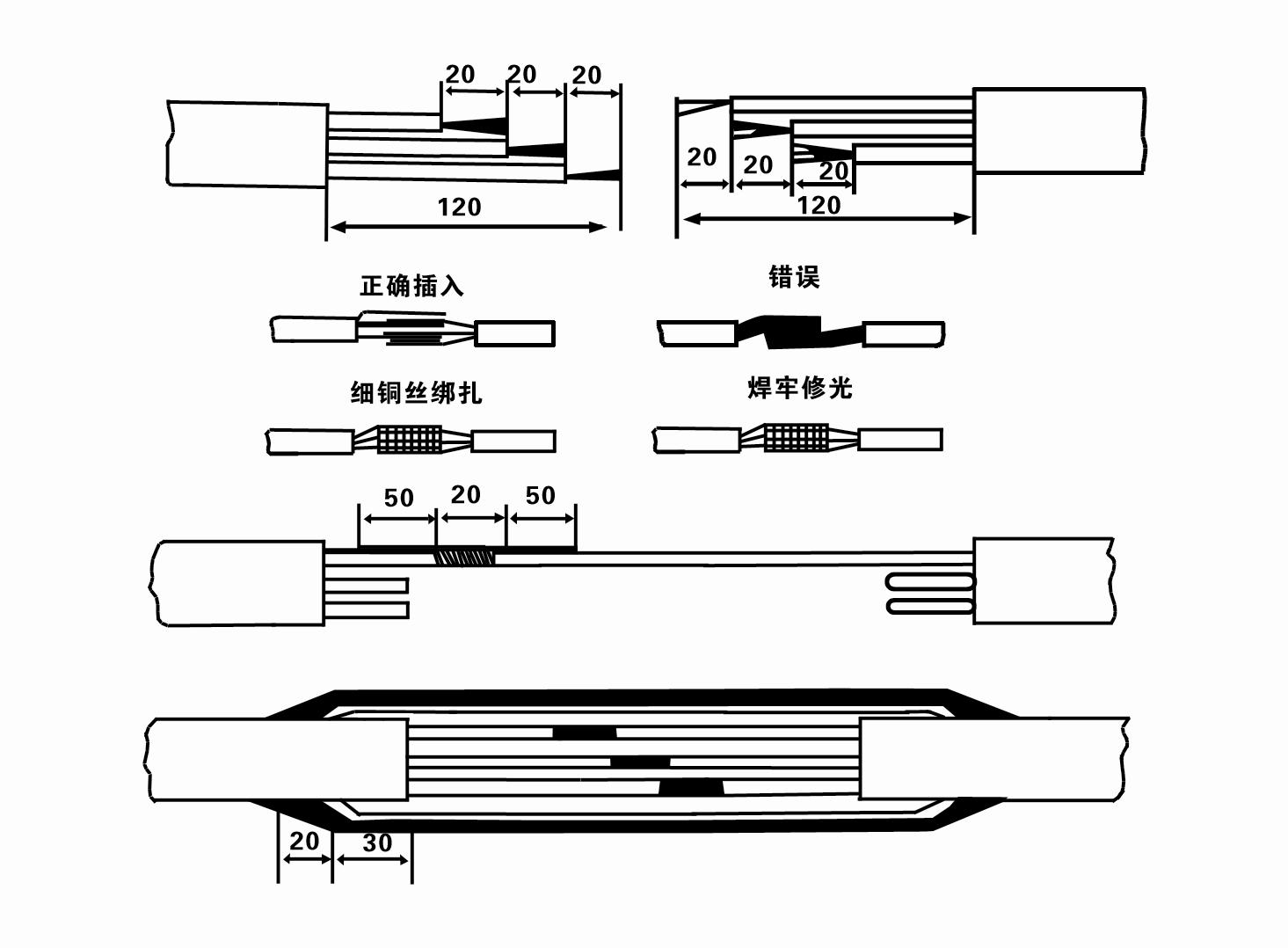
8. Benotzt e Multimeter fir z'iwwerpréiwen ob d'Drei-Phas-Drähte verbonne sinn an ob d'DC-Resistenz ongeféier ausgeglach ass.
9. Kontrolléiert ob de Circuit an den Transformatorkapazitéit iwwerlaascht sinn, a verbënnt dann den Iwwerlaaschtschutzschalter oder Startausrüstung. Gesinn Table 2 fir spezifesch Modeller, an dann Pour engem Eemer Waasser an d'Waasser Pompel aus dem Waasser Pompel Outlet der Gummistécker Lager an der Pompel ze schmieren, an dann Plaz der submersible elektresch Pompel oprecht a steady.Start (net méi wéi eng Sekonn) a kontrolléiert ob d'Steierungsrichtung mat dem Lenkzeechen konsequent ass. Wann net, swap all zwee Stecker vun der dräi-Phase Kabel. Dann installéiert de Filter a preparéieren der gutt erof goen. Wann se a speziellen Occasiounen benotzt ginn (wéi Grape, Gruef, Flëss, Weiere, Weiere, etc.), muss d'elektresch Pompel zouverlässeg Buedem sinn.
(2) Installatioun Ausrüstung an Tools:
1. Ee Paar Liftketten fir méi wéi zwee Tonnen.
2. E Stativ mat enger vertikaler Héicht vun net manner wéi véier Meter.
3. Zwee hängend Seeler (Draadseeler), déi e Gewiicht vu méi wéi engem Ton droen kënnen (kann d'Gewiicht vun engem komplette Set vu Waasserpompelen droen).
4. Installéiert zwee Puer Klameren (Splint).
5. Wrenches, Hammers, screwdrivers, elektresch Handwierksgeschir an Instrumenter, etc.
(3) Elektresch Pompel Installatioun:
1. D'Installatiounsdiagramm vun der Tauchpompel gëtt an der Figur 2. Déi spezifesch Installatiounsdimensioune ginn an der Tabell 3 "Lëscht vun Installatiounsdimensioune vun der Tauchtpompel" gewisen.
2. Submersibel elektresch Pompelen mat engem Kapp manner wéi 30 Meter kënnen direkt an d'Brunn geheien ginn mat Schlauchen a Drahtseeler oder aner Hanf Seeler, déi de ganze Gewiicht vun der ganzer Maschinn, Waasserleitungen a Waasser an de Päifen droen kënnen.
3. Pompelen mat engem Kapp vu méi wéi 30 Meter benotzen Stahlleitungen, an d'Installatiounssequenz ass wéi follegt:
①Benotzt eng Klemm fir den ieweschten Enn vum Waasserpompeldeel ze klemmen (de Motor a Waasserpompel sinn zu dësem Zäitpunkt ugeschloss), hieft se mat enger hängender Kette op, a bindt se lues an d'Brunn bis d'Klemm op de Brunnkopf setzt an d'Klemm erofhuelen. hängend Kette.
② Benotzt en anert Pair vu Klameren fir e Päif ze klemmen, hieft et mat enger hängender Kette 15 cm ewech vum Flange, a setzt se lues erof. Zwëschen Päifflens a Pompelflens Setzt d'Gummi-Pad op der Plaz a spannen d'Päif a pompelen gläichméisseg mat Bolzen, Nëss a Fréijoerswäschen.
③ Lift d'Tauchtpompel liicht op, huelt d'Klemm op der ieweschter Enn vun der Waasserpompel erof, bannen de Kabel fest an d'Waasserleitung mat engem Plastiksband, a bannen se lues erof bis D'Klemm op der Wellhead plazéiert ass.
④Benotz déiselwecht Method fir all Waasserleitungen an d'Bunn ze verbannen.
⑤Nodeems de Lead-Out-Kabel un de Kontrollschalter ugeschloss ass, ass et mat der Dräi-Phase-Energieversuergung ugeschloss.
(4) Saachen ze notéieren während der Installatioun:
1. Wann e Stau-Phänomen während dem Pompelprozess fonnt gëtt, dréit oder zitt d'Waasserleitung fir de Staupunkt ze iwwerwannen. Wann verschidde Moossnamen nach ëmmer net funktionnéieren, w.e.g. Kraaft d'Pompel net erof fir Schued un der Tauchtpompel an der Brunn ze vermeiden.
2. Bei der Installatioun sollt e Gummi-Pad am Flange vun all Päif plazéiert ginn a gläichméisseg festgehalen ginn.
3. Wann d'Waasserpompel an d'Wuel erofgesat gëtt, sollt et an der Mëtt vun der Brunnpipe plazéiert ginn, fir datt d'Pompel net laang géint d'Wuelmauer leeft, sou datt d'Pompel vibréiert an de Motor schëdden a brennt. .
4. Bestëmmt d'Tiefe vun der Waasserpompel bis zum Buedem vun der Brunn no de fléissende Sand a Siltbedingunge vun der Brunn. Begruewen d'Pompel net am Bulli. D'Distanz vun der Waasserpompel bis zum Enn vun der Brunn ass normalerweis net manner wéi 3 Meter (kuckt Figur 2).
5. D'Waasserentrée Tiefe vun der Waasserpompel sollt net manner wéi 1-1,5 Meter vum dynamesche Waasserniveau op d'Waasserinletknuet sinn (kuckt Figur 2). Soss kënnen d'Waasserpompellager liicht beschiedegt ginn.
6. De Lift vun der Waasserpompel kann net ze niddreg sinn. Soss muss e Paartventil op der Wellhead Waasserleitung installéiert ginn fir de Pompelstroum um bewäertte Flosspunkt ze kontrolléieren fir ze verhënneren datt de Motor iwwerlaascht a verbrannt gëtt wéinst grousse Flowraten.
7. Wann d'Waasserpompel leeft, soll d'Waasserausgang kontinuéierlech sinn a souguer, de Stroum soll stabil sinn (ënner bewäertte Aarbechtsbedingunge, allgemeng net méi wéi 10% vum bewäerten Stroum), an et sollt keng Schwéngung oder Kaméidi sinn. Wann et eng Anomalie ass, sollt d'Maschinn gestoppt ginn fir d'Ursaach erauszefannen an ze eliminéieren.
8. Beim Installatioun, oppassen op d'Astellung vum Motor Buedemdraad (kuckt Bild 2). Wann d'Waasser Päif e Stol Päif ass, féiert et aus der wellhead clamp; wann d'Waasserleitung e Plastiksleit ass, féiert se vun der Äerdmarke vun der elektrescher Pompel.
After the installation of the underwater pump, the insulation resistance and three-phase continuity of the switch face should be rechecked, and the connection between the instrument and the start device should be checked for any errors. If there is no problem, you can start to test the machine. After the start, observe whether the indication readings of each instrument are correct. If the rated voltage and current specified on the nameplate are exceeded, observe whether the pump has noise or vibration. If everything is normal, it can be put into operation. After the first operation of the pump for four hours, the motor should be shut down and tested for thermal insulation resistance quickly. Its value should not be less than 0.5 megaohm. After stopping the pump, it should be restarted after an interval of five minutes to prevent the water column in the pipeline from completely reversing and causing the motor to burn out due to excessive current. After the pump is put into normal operation, in order to prolong its service life, it is necessary to check regularly whether the supply voltage, running current and insulation resistance are normal. If the following conditions are found, the machine should be shut down immediately to eliminate the fault: the current exceeds 20% under rated working conditions; the dynamic water level drops to the inlet section, resulting in intermittent drainage; the underwater pump becomes violently vibrating or making noise; the supply voltage is lower than 340 volts; a fuse is blown out; the water pipe is damaged; the motor's thermal insulation resistance to the earth is less than 0.5 megaohm. The sequence of disassembly is: untie the cable fastening, remove the pipeline part, remove the line protection plate, screw down the water discharge bolt and discharge all the water in the motor chamber, remove the filter and loosen the coupling fixing screw of the motor shaft. The sequence of disassembly of the pump is: (see Figure 1) inlet section, impeller, guide housing, impeller, check the valve body. When removing the impeller, use special tools to loosen the taper sleeve of the impeller. Avoid bending the pump shaft and damaging the components throughout the process. The disassembly process of the motor is: (see Figure 1) put the motor on the platform, and remove the bolts, base, shaft head lock nut, thrust plate, key, lower guide plate (transverse bolt), bearing seat, screw knife seat from the bottom of the motor in order (take care not to damage the winding), and finally remove the connecting part and the upper guide bearing seat. Before assembling the unit, the rust and dirt of each part should be cleaned, and the sealant should be applied to each mating surface and fastener, and then assembled in reverse order of disassembly (the movement of the motor shaft after assembly is about one millimeter). After assembly, the coupling should be rotated flexibly and put on the filter for test. Once a year, or if less than a year of operation but has been immersed for two years, the underwater electric pump must be disassembled for maintenance in accordance with Article 5 and replace worn parts to ensure the normal operation and durability of the pump.
1, setzt d'Waasser an d'Motorkavitéit eraus (besonnesch am Wanter fir ze verhënneren datt de Motor gefruer ass), a verbënnt de Kabel gutt.
2, store in an indoor room without corrosive substances and gases, with a temperature below 40 °C.
3, laangfristeg Notzung sollt op d'Rostverhënnerung vun Tauchpompelen oppassen.
- Impeller
- Schaft Hülse
- Gummistécker Schacht Hülse
-
Dichtungsring
01 Déift gutt Waasser ofgeroden
02 Héichwaasserversuergung
03 Bierg Waasser Fourniture
04 Tuerm Waasser
05 Landwirtschaftlech Bewässerung
06 Gaart Bewässerung
07 Floss Waasser ofgeroden
08 Hauswaasser

