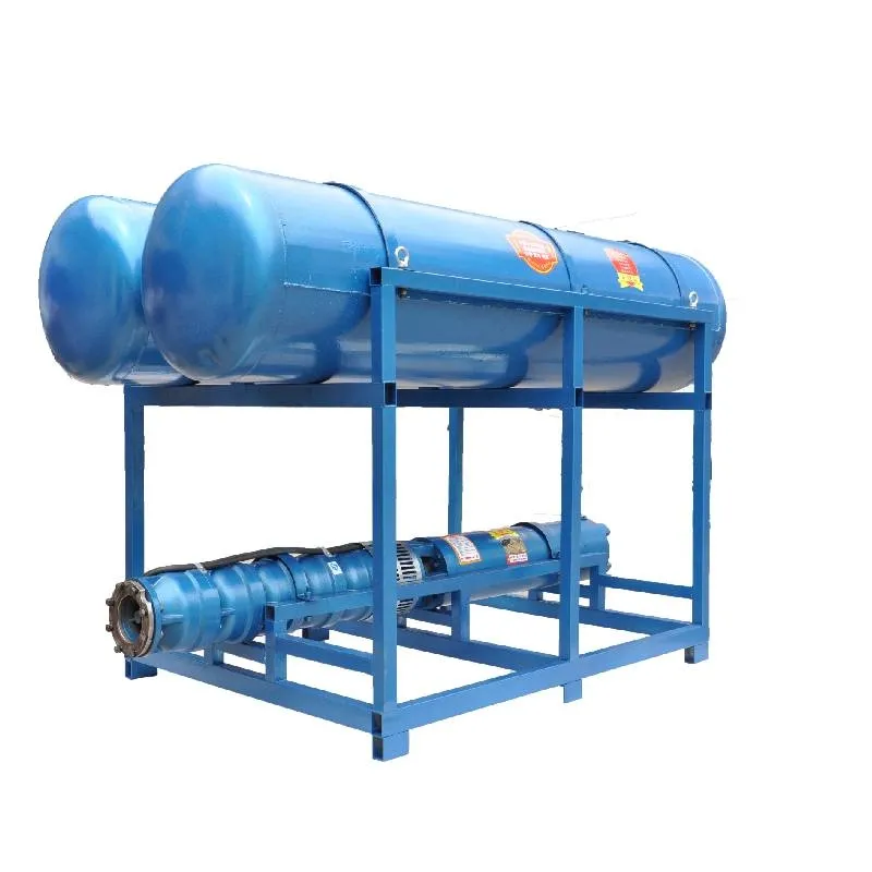
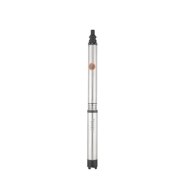
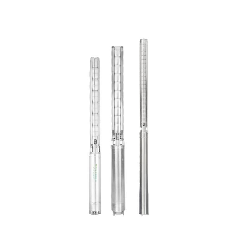
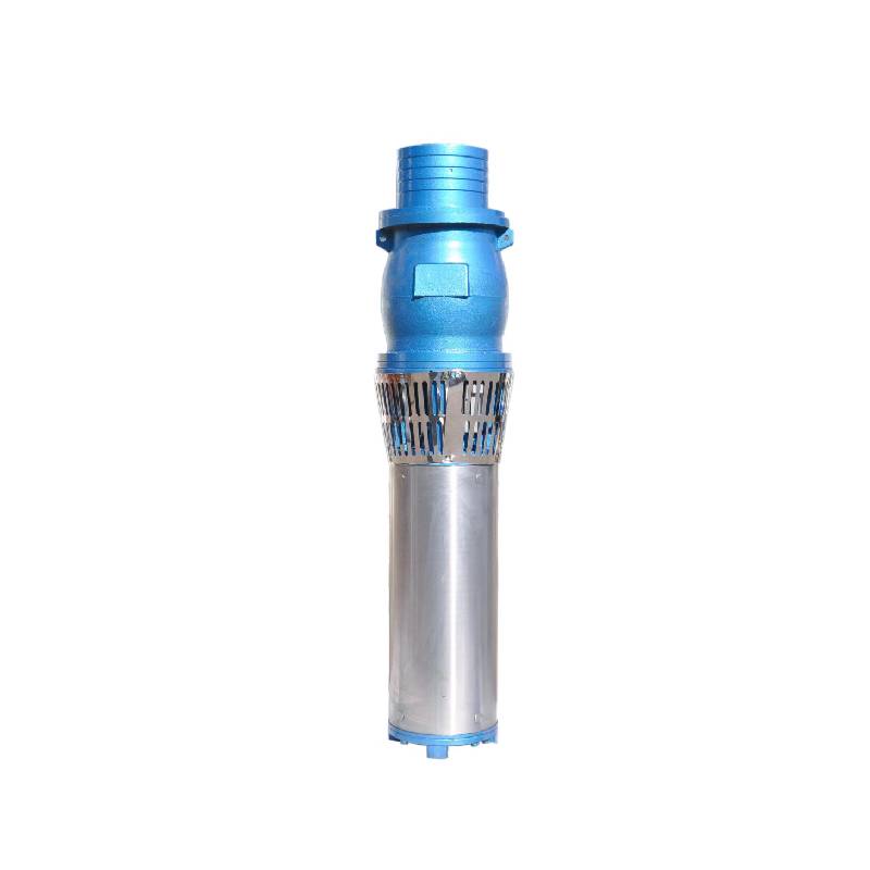
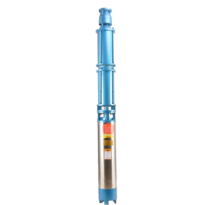
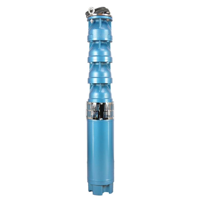
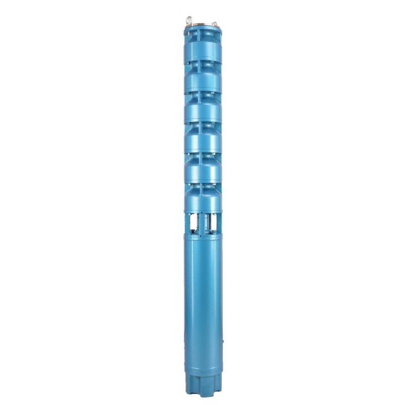
Frequency conversion winding design, ensure the motor in 1HZ-50HZ long-term stable conversion operation. Energy saving, longer service life.
1, aflgjafi: þriggja fasa AC 380V (vikmörk + / - 5%), 50HZ (vikmörk + / - 1%).
2, vatnsgæði:
(1) water temperature is not higher than 20 °C;
(2) innihald óhreininda í föstu formi (massahlutfall) er ekki meira en 0,01%;
(3) PH gildi (pH) 6,5-8,5;
(4) brennisteinsvetnisinnihald er ekki meira en 1,5mg/L;
(5) innihald klóríðjóna er ekki meira en 400mg/L.
3, mótorinn er lokaður eða vatnsfylltur blautur uppbygging, fyrir notkun verður kafmótorholið að vera fullt af hreinu vatni, til að koma í veg fyrir falskt fullt, og hertu síðan vatnsinnspýtingu, loftlosunarbolta, annars ekki leyfilegt að nota
4, kafdæla verður að vera alveg á kafi í vatni, köfunardýpt er ekki meira en 70m, botn dælunnar frá botni brunnsins er ekki minna en 3m.
5, brunninn vatnsrennsli ætti að geta mætt niðurdæluvatnsútstreymi og stöðugri notkun, niðurdæluvatnsframleiðsla ætti að vera stjórnað við 0,7 - 1,2 sinnum hlutfallsrennsli.
6, brunnurinn ætti að vera beinn, ekki er hægt að nota eða henda niðurdælu, aðeins lóðrétt notkun.
7, kafdælan verður að passa við kapalinn í samræmi við kröfurnar og ytri ofhleðsluvarnarbúnaðinn. 8, dælan er stranglega bönnuð án vatnslausrar prófunarvélar
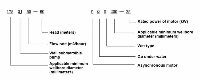
| Fyrirmynd | Rennsli (m3/klst.) | Höfuð (m) |
Rotating speed(change/point) | Vatns pumpa(%) | Útrás þvermál (mm) |
Gildir vel þvermál (mm) |
Metið afl (KW) |
Rated voltage(V) | Ratedcurrent(A) | Mótorafköst (%) | power factorcosφ | Eining Radial Maximu stærð (mm) |
Athugasemd | |||||||||
| 125QJ5-34 | 5 | 34 | 2850 | 53 | 40 | 125hér að ofan | 1.5 | 380 | 4.23 | 70.0 | 0.77 | 118 | ||||||||||
| 125QJ5-51 | 51 | 2.2 | 6.03 | 72.0 | 0.77 | |||||||||||||||||
| 125QJ5-68 | 68 | 3 | 8.01 | 73.0 | 0.78 | |||||||||||||||||
| 125QJ5-85 | 85 | 4 | 10.53 | 74.0 | 0.78 | |||||||||||||||||
| 125QJ5-102 | 102 | 5.5 | 14.1 | 75.0 | 0.79 | |||||||||||||||||
| 125QJ5-119 | 119 | 5.5 | 14.1 | 75.0 | 0.79 | |||||||||||||||||
| 125QJ10-24 | 10 | 24 | 2850 | 60 | 50 | 125hér að ofan | 1.5 | 380 | 4.23 | 70.0 | 0.77 | 118 | ||||||||||
| 125QJ10-32 | 32 | 2.2 | 6.03 | 72.0 | 0.77 | |||||||||||||||||
| 125QJ10-48 | 48 | 3 | 8.01 | 73.0 | 0.78 | |||||||||||||||||
| 125QJ10-56 | 56 | 4 | 10.53 | 74.0 | 0.78 | |||||||||||||||||
| 125QJ10-72 | 72 | 5.5 | 14.1 | 75.0 | 0.79 | |||||||||||||||||
| 125QJ10-80 | 80 | 5.5 | 14.1 | 75.0 | 0.79 | |||||||||||||||||
| 125QJ10-104 | 104 | 7.5 | 19.0 | 76.0 | 0.79 | |||||||||||||||||
| 125QJ10-120 | 10 | 120 | 2850 | 60 | 50 | 125hér að ofan | 7.5 | 380 | 19.0 | 76.0 | 0.79 | 118 | ||||||||||
| 125QJ10-136 | 136 | 9.2 | 22.7 | 77.0 | 0.8 | |||||||||||||||||
| 125QJ15-36 | 15 | 36 | 2850 | 63 | 50 | 125hér að ofan | 2.2 | 380 | 6.03 | 72.0 | 0.77 | 118 | ||||||||||
| 125QJ15-39 | 39 | 3 | 8.01 | 73.0 | 0.78 | |||||||||||||||||
| 125QJ15-46 | 46 | 4 | 10.53 | 74.0 | 0.78 | |||||||||||||||||
| 125QJ15-52 | 52 | 4 | 10.53 | 74.0 | 0.78 | |||||||||||||||||
| 125QJ15-59 | 59 | 5.5 | 14.1 | 75.0 | 0.79 | |||||||||||||||||
| 125QJ15-65 | 65 | 5.5 | 14.1 | 75.0 | 0.79 | |||||||||||||||||
| 125QJ15-78 | 78 | 7.5 | 19.0 | 76.0 | 0.79 | |||||||||||||||||
| 125QJ15-91 | 91 | 7.5 | 19.0 | 76.0 | 0.79 | |||||||||||||||||
| 125QJ15-104 | 104 | 9.2 | 22.7 | 77.0 | 0.8 | |||||||||||||||||
| 125QJ20-16 | 20 | 16 | 2850 | 64 | 50 | 125hér að ofan | 2.2 | 380 | 6.03 | 72.0 | 0.77 | 118 | ||||||||||
| 125QJ20-24 | 24 | 3 | 8.01 | 73.0 | 0.78 | |||||||||||||||||
| 125QJ20-32 | 32 | 4 | 10.53 | 74.0 | 0.78 | |||||||||||||||||
| 125QJ20-40 | 40 | 4 | 10.53 | 74.0 | 0.78 | |||||||||||||||||
| 125QJ20-48 | 48 | 5.5 | 14.1 | 75.0 | 0.79 | |||||||||||||||||
| 125QJ20-56 | 56 | 5.5 | 14.1 | 75.0 | 0.79 | |||||||||||||||||
| 125QJ20-64 | 64 | 7.5 | 19.0 | 76.0 | 0.79 | |||||||||||||||||
| 125QJ20-72 | 72 | 7.5 | 19.0 | 76.0 | 0.79 | |||||||||||||||||
| 125QJ20-80 | 80 | 9.2 | 22.7 | 77.0 | 0.8 | |||||||||||||||||
| 125QJ25-12 | 25 | 12 | 2850 | 64 | 65 | 125hér að ofan | 2.2 | 380 | 6.03 | 72.0 | 0.77 | 118 | ||||||||||
| 125QJ25-18 | 18 | 3 | 8.01 | 73.0 | 0.78 | |||||||||||||||||
| 125QJ25-24 | 24 | 4 | 10.53 | 74.0 | 0.78 | |||||||||||||||||
| 125QJ25-30 | 30 | 4 | 10.53 | 74.0 | 0.78 | |||||||||||||||||
| 125QJ25-36 | 36 | 5.5 | 14.1 | 75.0 | 0.79 | |||||||||||||||||
| 125QJ25-48 | 48 | 7.5 | 19.0 | 76.0 | 0.79 | |||||||||||||||||
| 125QJ25-60 | 60 | 9.2 | 22.7 | 77.0 | 0.8 | |||||||||||||||||
| 125QJ32-24 | 32 | 24 | 2850 | 64 | 80 | 125hér að ofan | 4 | 380 | 10.53 | 74.0 | 0.78 | 118 | ||||||||||
| 125QJ32-30 | 30 | 5.5 | 14.1 | 75.0 | 0.79 | |||||||||||||||||
| 125QJ32-42 | 42 | 7.5 | 19.0 | 76.0 | 0.79 | |||||||||||||||||
| 125QJ32-54 | 54 | 9.2 | 22.7 | 77.0 | 0.8 | |||||||||||||||||
| 125QJ5-240 | 5 | 240 | 2850 | 40 | 125hér að ofan | 11 | 380 | 26.28 | 118 | |||||||||||||
| 125QJ5-280 | 280 | 13 | 30.87 | |||||||||||||||||||
| 125QJ5-320 | 320 | 15 | 35.62 | |||||||||||||||||||
| 125QJ10-180 | 10 | 180 | 2850 | 50 | 125hér að ofan | 11 | 380 | 26.28 | 118 | |||||||||||||
| 125QJ10-210 | 210 | 13 | 30.87 | |||||||||||||||||||
| 125QJ10-240 | 240 | 15 | 35.62 | |||||||||||||||||||
| 125QJ15-120 | 15 | 120 | 2850 | 50 | 125hér að ofan | 11 | 380 | 26.28 | 118 | |||||||||||||
| 125QJ15-142 | 142 | 13 | 30.87 | |||||||||||||||||||
| 125QJ15-162 | 162 | 15 | 35.62 | |||||||||||||||||||
| 125QJ20-100 | 20 | 100 | 2850 | 50 | 125hér að ofan | 11 | 380 | 26.28 | 118 | |||||||||||||
| 125QJ20-120 | 120 | 13 | 30.87 | |||||||||||||||||||
| 125QJ20-136 | 136 | 15 | 35.62 | |||||||||||||||||||
| 125QJ25-82 | 25 | 82 | 2850 | 65 | 125hér að ofan | 11 | 380 | 26.28 | 118 | |||||||||||||
| 125QJ25-97 | 97 | 13 | 30.87 | |||||||||||||||||||
| 125QJ25-110 | 110 | 15 | 35.62 | |||||||||||||||||||
| 125QJ32-68 | 32 | 68 | 2850 | 80 | 125hér að ofan | 11 | 380 | 26.28 | 118 | |||||||||||||
| 125QJ32-80 | 80 | 13 | 30.87 | |||||||||||||||||||
| 125QJ32-92 | 92 | 15 | 35.62 | |||||||||||||||||||
| 125QJ40-46 | 40 | 46 | 2850 | 80 | 125hér að ofan | 11 | 380 | 26.28 | 118 | |||||||||||||
| 125QJ40-54 | 54 | 13 | 30.87 | |||||||||||||||||||
| 125QJ40-62 | 62 | 15 | 35.62 | |||||||||||||||||||
The well submersible pump is a pump suitable for clear water. It is strictly prohibited to dig new wells and pump out mud and sand. The voltage grade of the well pump is 380V/50HZ, and other voltage grades of the submersible motor need to be customized. Underground cables must be waterproof cables and must be equipped with starting equipment, such as distribution box, etc. The starting equipment should have common motor comprehensive protection functions, such as short circuit overload protection, phase loss protection, undervoltage protection, grounding protection and idling protection, etc. In abnormal cases, the protective device should be tripped in time. When installing and using the pump, it must be firmly grounded. It is prohibited to push and pull the switch when the hands and feet are wet. The power supply must be cut off before installing and maintaining the pump. An obvious "anti-electric shock" sign must be set up where the pump is used. Before going down the well or installing the motor, the inner cavity must be filled with distilled water or non-corrosive clean cold water, and the water injection/drainage bolts must be tightened. Fill the pump with water for ground test to lubricate the rubber bearings. The instant start time shall not exceed one second to check whether the direction is correct and consistent with the direction indication. Be sure to pay attention to safety when placing the pump upright to prevent overturning and causing injury. Strictly in accordance with the provisions of the pump lift and flow range of use, to prevent the pump flow at low lift or excessive pull at high lift, resulting in extreme wear of thrust bearings and other components, resulting in motor overload burn. After the pump into the well, the insulation resistance between the motor and the ground shall be measured, which shall not be less than 100MΩ. After the start, observe the voltage and current regularly, and check the motor winding insulation, to see if it meets the requirements; if the pump storage temperature is below the freezing point, the water in the motor cavity should be discharged, so as to avoid the water in the motor cavity freezing and damaging the motor due to low temperature.
Helstu eiginleikar vörunnar eru:
1.The motor is a water-loaded wet submersible three-phase asynchronous motor,and the motor cavity is filled with clean water for cooling the motor and lubricating the bearing.The regulating diaphragm at the bottom of the motor is used to adjust the expansion and contraction pressure difference inside and outside the body caused by the temperature rise of the motor.
2.In order to prevent the sand particles in the well water from entering the motor,two oil seals are installed at the extension end of the motor shaft,and the sand ring is installed to form a sand prevention structure.
3.In order to prevent the pump shaft from jumping when starting,the pump shaft is connected with the motor shaft through a coupling,and the thrust bearing is installed at the bottom of the motor.
4.The lubrication of the motor and the pump bearing is water lubrication.
5.The stator winding of the motor adopts high-quality submersible motor winding wire,with excellent insulation performance.
6.The pump is designed by computer CAD,with simple structure and excellent technical performance.

(1) Undirbúningur fyrir uppsetningu:
1. Athugaðu hvort niðurdælan uppfylli notkunarskilyrði og umfang sem tilgreint er í handbókinni.
2. Notaðu þungan hlut með þvermál sem er jafnt og hámarks ytra þvermál dælu dælunnar, mæltu hvort innri þvermál holunnar passi niðurdælu og mæliðu hvort dýpt holunnar uppfylli kröfur um uppsetningu.
3. Athugaðu hvort holan sé hrein og hvort brunnvatnið sé gruggugt. Notaðu aldrei rafmagnsdælu til að þvo velordæluna leðju og sandvatn til að forðast ótímabæra skemmdir á rafdælunni.
4. Athugaðu hvort staðsetning uppsetningarklemmunnar sé hentug og hvort hún þolir gæði alls einingarinnar
5. Athugaðu hvort íhlutir kafdælunnar séu fullbúnir og rétt uppsettir samkvæmt samsetningarmyndinni í handbókinni. Fjarlægðu síuskjáinn og snúðu tenginu til að sjá hvort hún snýst sveigjanlegan
6. Skrúfaðu vatnsskrúfuna af og fylltu mótorholið með hreinu, ætandi vatni (athugið. vertu viss um að fylla það upp), hertu síðan á vatnsskrúfuna. Eftir 12 klukkustunda vatnsdælingu ætti einangrunarviðnám mótorsins ekki að vera minna en 150M Q þegar það er mælt með 500V hristingsborði.
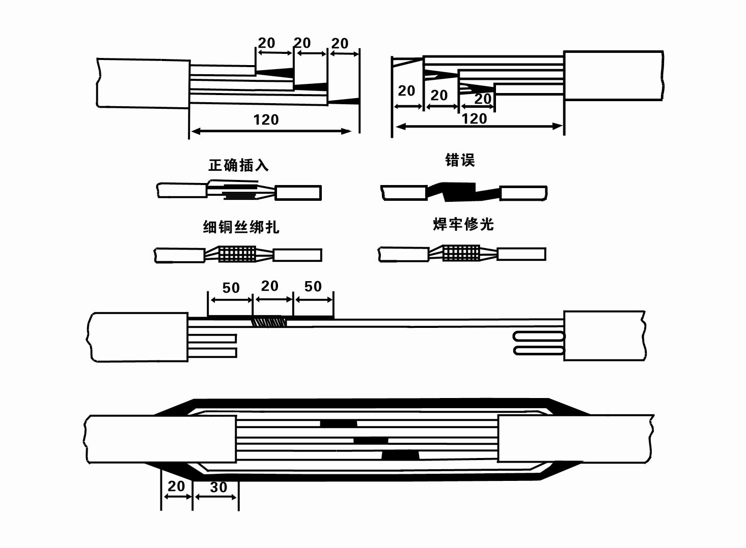
7. Cable joint, cut off a 120mm rubber sleeve from one end of the outgoing cable and the matching cable with an electrician's knifethen stagger the length of the three core wires in a stepped shape, peel off a 20mm copper core, scrape of the oxide layer on theoutside of the copper wire with a knife or sand cloth, and insert the two connected wire ends in palirs.
After tying the layer tightly with fine copper wire, solder it thoroughly and firmly, and sand of any. burrs on the surface. Then, forthe three joints, use polyvester insulation tape to wrap them in a semi stacked manner for three lavers. Wrap the two ends of thewrapping layer tightywith nyion thread,and then use a semi stacked method to wrap the tape for three layers. Wrap the outellayer with high-pressure insulation tape for three layers. Finally, fold the threestrands together and repeatedly wrap them for fivelayers with high-pressure tape. Each layer must be tightly tied, and the interlayer joints must be tight and fimm to prevent water frompenetrating and damaging the insulation, After wrapping, soak in water at room temperature of 20 ’c for 12 hours, and measurethe insulation resistance with a shaking table, which should not be less than 100M Ω
Meðfylgjandi skýringarmynd um snúrunarferli er sem hér segir:
8. Notaðu margmæli til að athuga hvort þrífasa vírarnir séu tengdir og hvort DC viðnámið sé um það bil jafnvægi.
9. Check whether the circuit and transformer capacity are overloaded, and then connect the overload protection switch or starting equipment. See Table 2 for specific models, and then
Pour a bucket of water into the water pump from the water pump outlet to lubricate the rubber bearings in the pump, and then place the submersible electric pump upright and steady.
Start (no more than one second) and check whether the steering direction is consistent with the steering sign. If not, swap any two connectors of the three-phase cable.
Then install the filter and prepare to go down the well. If used in special occasions (such as ditches, ditches, rivers, ponds, ponds, etc.), the electric pump must be reliably grounded.
(2) Uppsetningarbúnaður og verkfæri:
1. Eitt par af lyftikeðjum fyrir meira en tvö tonn.
2. Þrífótur með lóðrétta hæð sem er ekki minna en fjórir metrar.
3. Tvö hengireipi (vírareipi) sem geta borið meira en eitt tonn (geta borið þyngd heils vatnsdælusetts).
4. Settu upp tvö pör af klemmum (spelkum).
5. Skiplyklar, hamar, skrúfjárn, rafmagnsverkfæri og tæki o.fl.
(3) Uppsetning rafdælu:
1. Uppsetningarskýringarmynd rafdælunnar er sýnd á mynd 2. Sérstakar uppsetningarstærðir eru sýndar í töflu 3 "Listi yfir uppsetningarstærðir djúpdælunnar".
2. Rafdrifnar dælur sem eru undir 30 metrum að hæð má hífa beint í brunninn með því að nota slöngur og víra eða aðra hampi reipi sem geta borið alla þyngd vélarinnar, vatnsleiðslur og vatns í pípunum.
3. Dælur með yfir 30 metra hæð nota stálrör og uppsetningarröðin er sem hér segir:
①Use a clamp to clamp the upper end of the water pump part (the motor and water pump have been connected at this time), lift it with a hanging chain, and slowly tie it into the well until
Put the clamp on the wellhead and remove the hanging chain.
② Use another pair of clamps to clamp a pipe, lift it with a hanging chain 15 cm away from the flange, and lower it slowly. Between pipe flange and pump flange
Put the rubber pad in place and tighten the pipe and pump evenly with bolts, nuts and spring washers.
③ Lyftu djúpdælunni örlítið, fjarlægðu klemmuna á efri enda vatnsdælunnar, bindðu snúruna þétt við vatnsrörið með plastbandi og festu hana hægt niður þar til klemman er sett við brunnhausinn.
④Notaðu sömu aðferð til að binda allar vatnsleiðslur í brunninn.
⑤Eftir að úttakssnúran er tengd við stjórnrofann er hún tengd við þriggja fasa aflgjafann.
(4) Atriði sem þarf að hafa í huga við uppsetningu:
1. If a jamming phenomenon is found during the pumping process, turn or pull the water pipe to overcome the jamming point. If various measures still do not work, please
Do not force the pump down to avoid damage to the submersible electric pump and the well.
2. Við uppsetningu skal setja gúmmípúða við flans hvers rörs og herða jafnt.
3. Þegar vatnsdælan er lækkuð niður í brunninn ætti að setja hana í miðja brunnspípuna til að koma í veg fyrir að dælan gangi á móti brunnveggnum í langan tíma, sem veldur því að dælan titrar og mótorinn sópar og brennir. .
4. Ákvarðu dýpt vatnsdælunnar í botn holunnar í samræmi við rennandi sand- og siltskilyrði holunnar. Ekki grafa dæluna í leðjuna. Fjarlægðin frá vatnsdælunni að botni holunnar er að jafnaði ekki minni en 3 metrar (sjá mynd 2).
5. Vatnsinntaksdýpt vatnsdælunnar ætti að vera ekki minna en 1-1,5 metrar frá kraftmiklu vatnsborðinu að vatnsinntakshnútnum (sjá mynd 2). Annars geta legur vatnsdælunnar auðveldlega skemmst.
6. Lyfta vatnsdælunnar má ekki vera of lágt. Að öðrum kosti þarf að setja hliðarventil á brunnhausvatnsleiðsluna til að stjórna dæluflæðinu á nafnflæðispunkti til að koma í veg fyrir að mótorinn verði ofhlaðinn og brennur út vegna mikils rennslishraða.
7. Þegar vatnsdælan er í gangi, ætti vatnsframleiðslan að vera stöðug og jöfn, straumurinn ætti að vera stöðugur (við metnaðarvinnuskilyrði, yfirleitt ekki meira en 10% af nafnstraumnum), og það ætti ekki að vera titringur eða hávaði. Ef það er eitthvað óeðlilegt ætti að stöðva vélina til að komast að orsökinni og útrýma henni.
8. Þegar þú setur upp skaltu fylgjast með stillingu jarðtengingarvírs mótorsins (sjá mynd 2). Þegar vatnsrörið er stálpípa skaltu leiða það frá brunnhausklemmunni; þegar vatnsrörið er plastpípa skaltu leiða það frá jarðtengingarmerki rafdælunnar.
- 1.Eftir að niðurdælan er sett upp, athugaðu einangrunarviðnám og þriggja fasa leiðni frá rofanum aftur, athugaðu hvort tækið og tenging ræsibúnaðarins sé rangt, ef ekkert vandamál er, er hægt að ræsa prufuvélina, og athugaðu hvort mælikvarðar tækisins fara yfir nafnspennu og straum sem tilgreind er á nafnplötunni eftir ræsingu, og athugaðu hvort dælan hafi hávaða og titring fyrirbæri og sett í gang ef allt er eðlilegt.
- 2.Eftir fyrstu notkun dælunnar í fjórar klukkustundir ætti að slökkva á mótornum til að prófa hitaeinangrunarviðnámið fljótt og gildi hans ætti ekki að vera minna en 0,5 megaohm.
- 3.Eftir að dælan hefur verið stöðvuð, ætti að ræsa hana eftir fimm mínútur til að koma í veg fyrir að vatnssúlan í pípunni flæði alveg aftur og valdi of miklum mótorstraumi og brennslu.
- 4.Eftir að dælan er tekin í venjulega notkun, til þess að lengja endingartíma hennar, er nauðsynlegt að athuga hvort framboðsspenna, vinnustraumur og einangrunarviðnám séu eðlileg reglulega. Ef eftirfarandi aðstæður finnast skal slökkva strax á dælunni til að leysa úr.
- 1 In the rated condition, the current exceeds 20%.
- 2 Kraftmikið vatnsborð lækkar niður í vatnsinntakshlutann, sem veldur því að vatn verður stöðvað.
- 3 Djúpdælan hefur mikinn titring eða hávaða.
- 4 Framboðsspennan er lægri en 340 volt.
- 5 Öryggi er brunnið út.
- 6 Vatnsveitulögnin er skemmd.
- 7 The motor's thermal insulation resistance is lower than 0.5 megaohm.
- Unit disassembly:
- 1.Untie the cable tie, remove the pipeline part, and remove the wire plate.
- 2.screw down the water bolt, put the water in the motor chamber.
- 3.remove the filter, loose the fixed screw on the coupling to fix the motor shaft.
- 4.screw down the bolt connecting the water inlet section with the motor, and separate the pump from the motor (pay attention to the unit cushion when separating, to prevent the bending of the pump shaft)
- 5.the disassembly sequence of the pump is: (see figure 1) water inlet section, impeller, diversion shell, impeller...... check valve body, when removing the impeller, use special tools to loosen the conical sleeve of the fixed impeller first, and avoid bending and bruising the pump shaft in the process of disassembly.
- 6.the disassembly process of the motor is: (see figure 1) place the motor on the platform, and remove the nuts, base, shaft head locking nut, thrust plate, key, lower guide bearing seat and double head bolt from the bottom of the motor in turn, and then take out the rotor (pay attention not to damage the wire package) and finally remove the connecting section and upper guide bearing seat.
- 7.unit assembly: before assembly, the rust and dirt of the parts should be cleaned, and the mating surface and fasteners coated with sealant, and then assembled in the opposite order of disassembly (the motor shaft moves up and down after assembly for about one millimeter), after assembly, the coupling should be flexible, and then the filter screen test machine. Submersible pumps shall be taken out of the well for dismantling and maintenance according to Article 5 after a year of operation, or less than a year of operation but two years of diving time, and the worn parts shall be replaced.
This product is an efficient and durable submersible electric pump, suitable for a variety of environments and applications.In order to ensure the long-term use and stable performance of the product, we suggest that users pay special attention to drying the water in the motor cavity in winter to avoid freezing; in addition, the cable is coiled and tied, and properly stored in an environment without corrosive substances and gases, with a temperature below 40 °C. If the product is not used for a long time, attention should be paid to rust prevention treatment to ensure the life cycle and performance of the product.Whether for industrial use or for home use, this submersible electric pump can provide you with reliable pump service.
-
- Hjólhjól
- Skafthylki
- Skafthylsa úr gúmmíi
-
Þéttihringur
01 Vatnsinntak djúpbrunns
02 Vatnsveita í háhýsum
03 fjallavatnsveita
04 turn vatn
05 Landbúnaðaráveita
06 garðáveita
07 vatnsinntaka ánna
08 heimilisvatn


