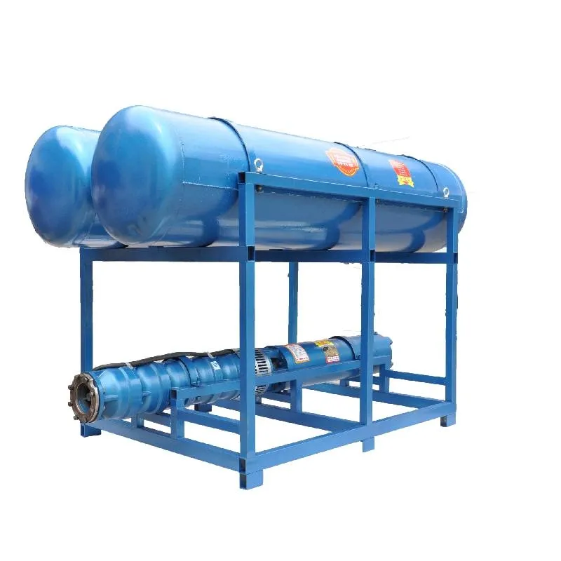
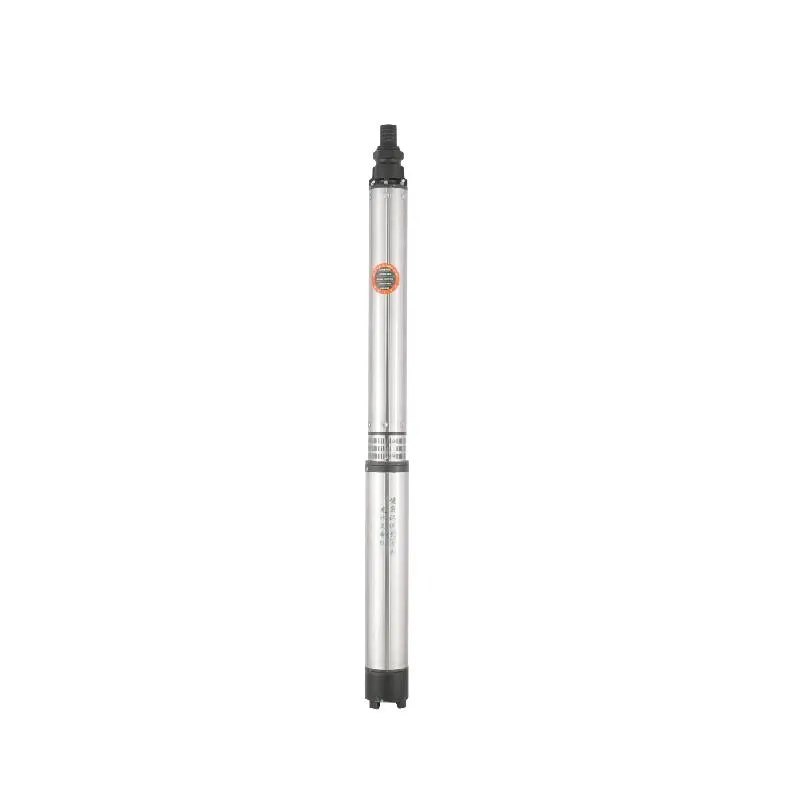
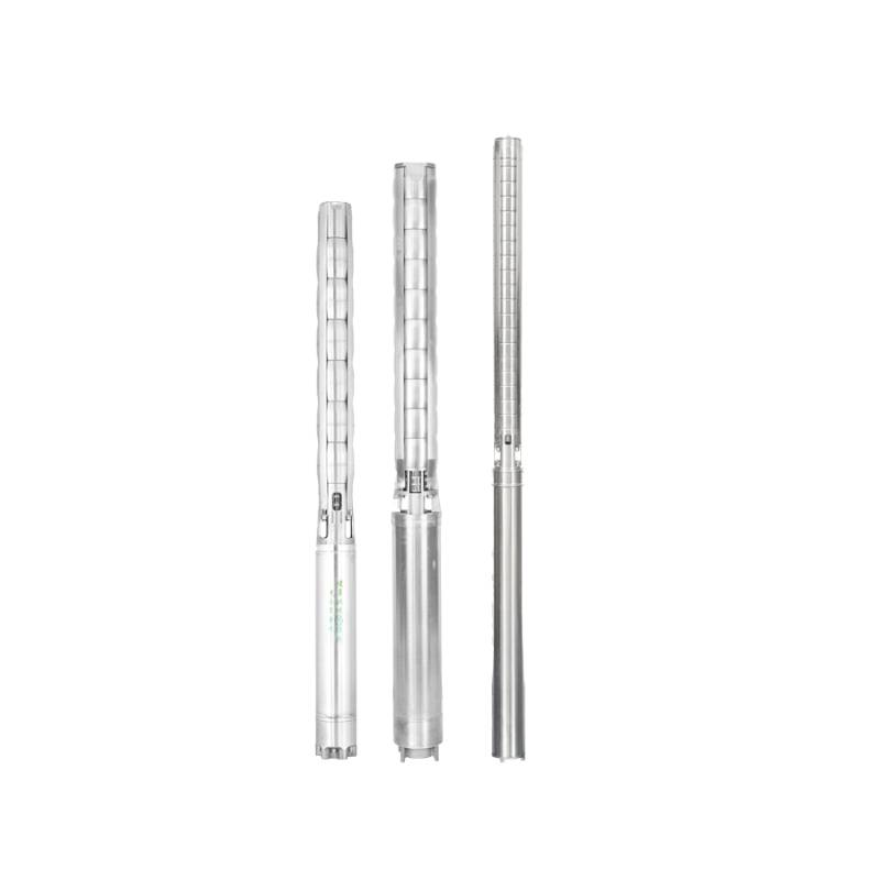
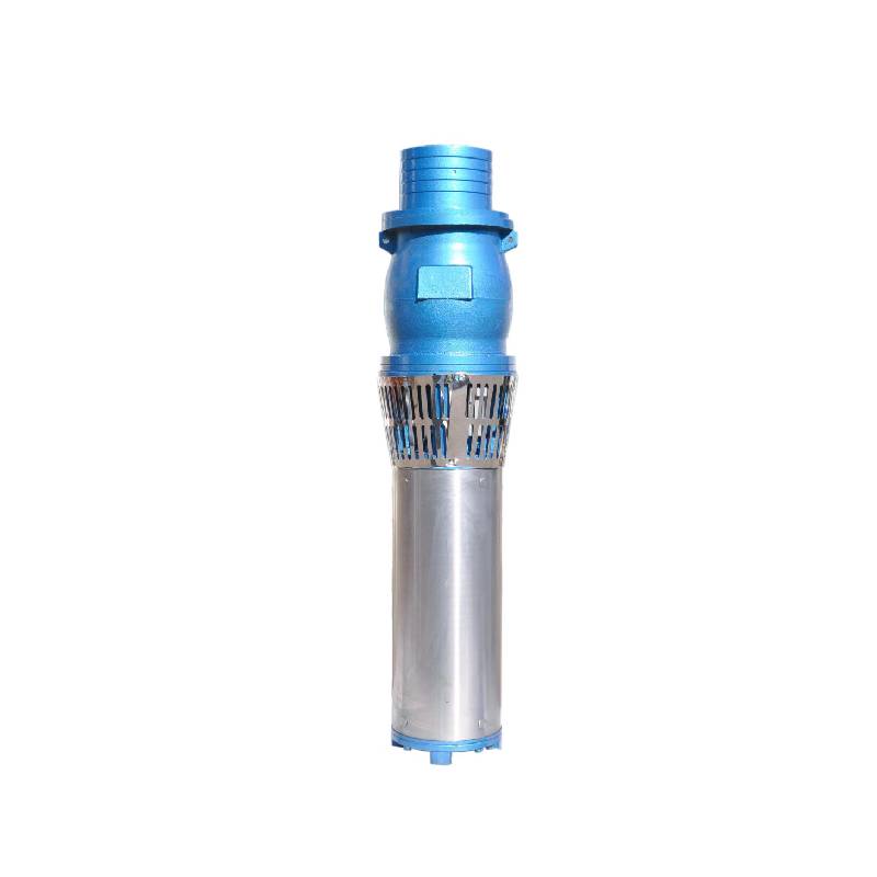
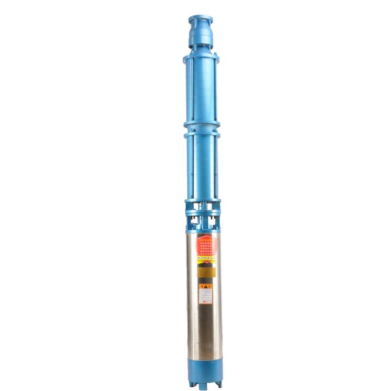
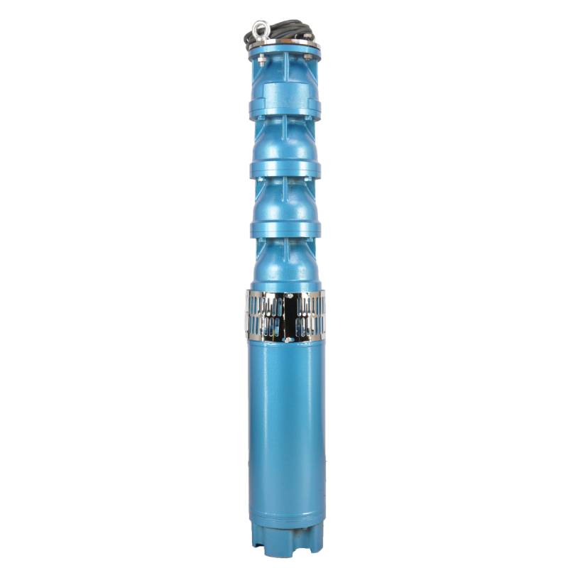
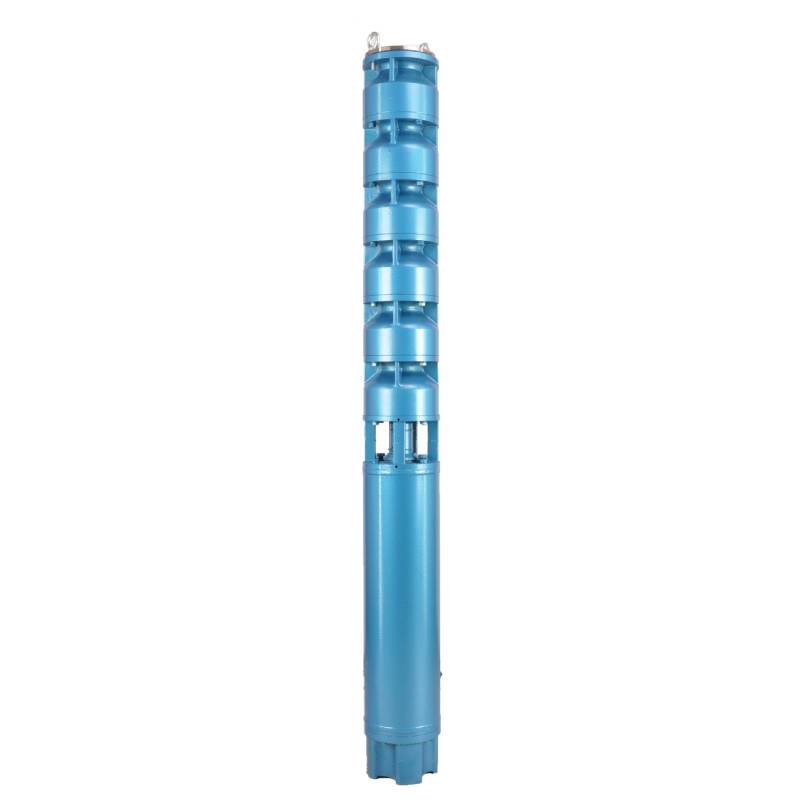
Frequency conversion winding design, ensure the motor in 1HZ-50HZ long-term stable conversion operation. Energy saving, longer service life.
1, strømforsyning: trefaset AC 380V (tolerance + / - 5%), 50HZ (tolerance + / - 1%).
2, vandkvalitet:
(1) water temperature is not higher than 20 °C;
(2) indhold af faste urenheder (masseforhold) ikke er større end 0,01 %;
(3) PH-værdi (pH) 6,5-8,5;
(4) hydrogensulfidindhold ikke er større end 1,5 mg/L;
(5) Chloridionindholdet er ikke større end 400mg/L.
3, motoren er lukket eller vandfyldt våd struktur, før brug skal det nedsænkelige motorhulrum være fyldt med rent vand, for at forhindre falsk fuld, og stram derefter vandindsprøjtningen, luftudløsningsbolte, ellers ikke tilladt at bruge
4, dykpumpe skal være helt nedsænket i vandet, dykkerdybden er ikke større end 70m, bunden af dykpumpen fra bunden af brønden er ikke mindre end 3m.
5, skal brøndvandstrømmen være i stand til at opfylde den dykpumpes vandydelse og kontinuerlig drift, den dykpumpevandsydelse skal styres til 0,7 - 1,2 gange den nominelle strøm.
6, brønden skal være lige, den dykpumpe kan ikke bruges eller dumpes, kun lodret brug.
7, skal dykpumpen matches med kablet i henhold til kravene og den eksterne overbelastningsbeskyttelsesanordning. 8, pumpen er strengt forbudt uden vand-no-load testmaskine
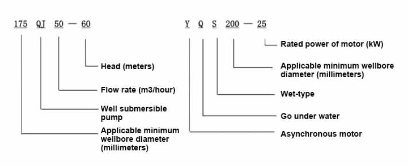
| Model | Flow (m3/h) | Hoved (m) |
Rotating speed(change/point) | Vandpumpe(%) | Udtag diameter (mm) |
Velegnet diameter (mm) |
Bedømt effekt (KW) |
Rated voltage(V) | Ratedcurrent(A) | Motoreffektivitet (%) | power factorcosφ | Enhed Radial maksimal størrelse (mm) |
Bemærkning | |||||||||
| 125QJ5-34 | 5 | 34 | 2850 | 53 | 40 | 125over | 1.5 | 380 | 4.23 | 70.0 | 0.77 | 118 | ||||||||||
| 125QJ5-51 | 51 | 2.2 | 6.03 | 72.0 | 0.77 | |||||||||||||||||
| 125QJ5-68 | 68 | 3 | 8.01 | 73.0 | 0.78 | |||||||||||||||||
| 125QJ5-85 | 85 | 4 | 10.53 | 74.0 | 0.78 | |||||||||||||||||
| 125QJ5-102 | 102 | 5.5 | 14.1 | 75.0 | 0.79 | |||||||||||||||||
| 125QJ5-119 | 119 | 5.5 | 14.1 | 75.0 | 0.79 | |||||||||||||||||
| 125QJ10-24 | 10 | 24 | 2850 | 60 | 50 | 125over | 1.5 | 380 | 4.23 | 70.0 | 0.77 | 118 | ||||||||||
| 125QJ10-32 | 32 | 2.2 | 6.03 | 72.0 | 0.77 | |||||||||||||||||
| 125QJ10-48 | 48 | 3 | 8.01 | 73.0 | 0.78 | |||||||||||||||||
| 125QJ10-56 | 56 | 4 | 10.53 | 74.0 | 0.78 | |||||||||||||||||
| 125QJ10-72 | 72 | 5.5 | 14.1 | 75.0 | 0.79 | |||||||||||||||||
| 125QJ10-80 | 80 | 5.5 | 14.1 | 75.0 | 0.79 | |||||||||||||||||
| 125QJ10-104 | 104 | 7.5 | 19.0 | 76.0 | 0.79 | |||||||||||||||||
| 125QJ10-120 | 10 | 120 | 2850 | 60 | 50 | 125over | 7.5 | 380 | 19.0 | 76.0 | 0.79 | 118 | ||||||||||
| 125QJ10-136 | 136 | 9.2 | 22.7 | 77.0 | 0.8 | |||||||||||||||||
| 125QJ15-36 | 15 | 36 | 2850 | 63 | 50 | 125over | 2.2 | 380 | 6.03 | 72.0 | 0.77 | 118 | ||||||||||
| 125QJ15-39 | 39 | 3 | 8.01 | 73.0 | 0.78 | |||||||||||||||||
| 125QJ15-46 | 46 | 4 | 10.53 | 74.0 | 0.78 | |||||||||||||||||
| 125QJ15-52 | 52 | 4 | 10.53 | 74.0 | 0.78 | |||||||||||||||||
| 125QJ15-59 | 59 | 5.5 | 14.1 | 75.0 | 0.79 | |||||||||||||||||
| 125QJ15-65 | 65 | 5.5 | 14.1 | 75.0 | 0.79 | |||||||||||||||||
| 125QJ15-78 | 78 | 7.5 | 19.0 | 76.0 | 0.79 | |||||||||||||||||
| 125QJ15-91 | 91 | 7.5 | 19.0 | 76.0 | 0.79 | |||||||||||||||||
| 125QJ15-104 | 104 | 9.2 | 22.7 | 77.0 | 0.8 | |||||||||||||||||
| 125QJ20-16 | 20 | 16 | 2850 | 64 | 50 | 125over | 2.2 | 380 | 6.03 | 72.0 | 0.77 | 118 | ||||||||||
| 125QJ20-24 | 24 | 3 | 8.01 | 73.0 | 0.78 | |||||||||||||||||
| 125QJ20-32 | 32 | 4 | 10.53 | 74.0 | 0.78 | |||||||||||||||||
| 125QJ20-40 | 40 | 4 | 10.53 | 74.0 | 0.78 | |||||||||||||||||
| 125QJ20-48 | 48 | 5.5 | 14.1 | 75.0 | 0.79 | |||||||||||||||||
| 125QJ20-56 | 56 | 5.5 | 14.1 | 75.0 | 0.79 | |||||||||||||||||
| 125QJ20-64 | 64 | 7.5 | 19.0 | 76.0 | 0.79 | |||||||||||||||||
| 125QJ20-72 | 72 | 7.5 | 19.0 | 76.0 | 0.79 | |||||||||||||||||
| 125QJ20-80 | 80 | 9.2 | 22.7 | 77.0 | 0.8 | |||||||||||||||||
| 125QJ25-12 | 25 | 12 | 2850 | 64 | 65 | 125over | 2.2 | 380 | 6.03 | 72.0 | 0.77 | 118 | ||||||||||
| 125QJ25-18 | 18 | 3 | 8.01 | 73.0 | 0.78 | |||||||||||||||||
| 125QJ25-24 | 24 | 4 | 10.53 | 74.0 | 0.78 | |||||||||||||||||
| 125QJ25-30 | 30 | 4 | 10.53 | 74.0 | 0.78 | |||||||||||||||||
| 125QJ25-36 | 36 | 5.5 | 14.1 | 75.0 | 0.79 | |||||||||||||||||
| 125QJ25-48 | 48 | 7.5 | 19.0 | 76.0 | 0.79 | |||||||||||||||||
| 125QJ25-60 | 60 | 9.2 | 22.7 | 77.0 | 0.8 | |||||||||||||||||
| 125QJ32-24 | 32 | 24 | 2850 | 64 | 80 | 125over | 4 | 380 | 10.53 | 74.0 | 0.78 | 118 | ||||||||||
| 125QJ32-30 | 30 | 5.5 | 14.1 | 75.0 | 0.79 | |||||||||||||||||
| 125QJ32-42 | 42 | 7.5 | 19.0 | 76.0 | 0.79 | |||||||||||||||||
| 125QJ32-54 | 54 | 9.2 | 22.7 | 77.0 | 0.8 | |||||||||||||||||
| 125QJ5-240 | 5 | 240 | 2850 | 40 | 125over | 11 | 380 | 26.28 | 118 | |||||||||||||
| 125QJ5-280 | 280 | 13 | 30.87 | |||||||||||||||||||
| 125QJ5-320 | 320 | 15 | 35.62 | |||||||||||||||||||
| 125QJ10-180 | 10 | 180 | 2850 | 50 | 125over | 11 | 380 | 26.28 | 118 | |||||||||||||
| 125QJ10-210 | 210 | 13 | 30.87 | |||||||||||||||||||
| 125QJ10-240 | 240 | 15 | 35.62 | |||||||||||||||||||
| 125QJ15-120 | 15 | 120 | 2850 | 50 | 125over | 11 | 380 | 26.28 | 118 | |||||||||||||
| 125QJ15-142 | 142 | 13 | 30.87 | |||||||||||||||||||
| 125QJ15-162 | 162 | 15 | 35.62 | |||||||||||||||||||
| 125QJ20-100 | 20 | 100 | 2850 | 50 | 125over | 11 | 380 | 26.28 | 118 | |||||||||||||
| 125QJ20-120 | 120 | 13 | 30.87 | |||||||||||||||||||
| 125QJ20-136 | 136 | 15 | 35.62 | |||||||||||||||||||
| 125QJ25-82 | 25 | 82 | 2850 | 65 | 125over | 11 | 380 | 26.28 | 118 | |||||||||||||
| 125QJ25-97 | 97 | 13 | 30.87 | |||||||||||||||||||
| 125QJ25-110 | 110 | 15 | 35.62 | |||||||||||||||||||
| 125QJ32-68 | 32 | 68 | 2850 | 80 | 125over | 11 | 380 | 26.28 | 118 | |||||||||||||
| 125QJ32-80 | 80 | 13 | 30.87 | |||||||||||||||||||
| 125QJ32-92 | 92 | 15 | 35.62 | |||||||||||||||||||
| 125QJ40-46 | 40 | 46 | 2850 | 80 | 125over | 11 | 380 | 26.28 | 118 | |||||||||||||
| 125QJ40-54 | 54 | 13 | 30.87 | |||||||||||||||||||
| 125QJ40-62 | 62 | 15 | 35.62 | |||||||||||||||||||
The well submersible pump is a pump suitable for clear water. It is strictly prohibited to dig new wells and pump out mud and sand. The voltage grade of the well pump is 380V/50HZ, and other voltage grades of the submersible motor need to be customized. Underground cables must be waterproof cables and must be equipped with starting equipment, such as distribution box, etc. The starting equipment should have common motor comprehensive protection functions, such as short circuit overload protection, phase loss protection, undervoltage protection, grounding protection and idling protection, etc. In abnormal cases, the protective device should be tripped in time. When installing and using the pump, it must be firmly grounded. It is prohibited to push and pull the switch when the hands and feet are wet. The power supply must be cut off before installing and maintaining the pump. An obvious "anti-electric shock" sign must be set up where the pump is used. Before going down the well or installing the motor, the inner cavity must be filled with distilled water or non-corrosive clean cold water, and the water injection/drainage bolts must be tightened. Fill the pump with water for ground test to lubricate the rubber bearings. The instant start time shall not exceed one second to check whether the direction is correct and consistent with the direction indication. Be sure to pay attention to safety when placing the pump upright to prevent overturning and causing injury. Strictly in accordance with the provisions of the pump lift and flow range of use, to prevent the pump flow at low lift or excessive pull at high lift, resulting in extreme wear of thrust bearings and other components, resulting in motor overload burn. After the pump into the well, the insulation resistance between the motor and the ground shall be measured, which shall not be less than 100MΩ. After the start, observe the voltage and current regularly, and check the motor winding insulation, to see if it meets the requirements; if the pump storage temperature is below the freezing point, the water in the motor cavity should be discharged, so as to avoid the water in the motor cavity freezing and damaging the motor due to low temperature.
De vigtigste egenskaber ved produktet omfatter:
1.The motor is a water-loaded wet submersible three-phase asynchronous motor,and the motor cavity is filled with clean water for cooling the motor and lubricating the bearing.The regulating diaphragm at the bottom of the motor is used to adjust the expansion and contraction pressure difference inside and outside the body caused by the temperature rise of the motor.
2.In order to prevent the sand particles in the well water from entering the motor,two oil seals are installed at the extension end of the motor shaft,and the sand ring is installed to form a sand prevention structure.
3.In order to prevent the pump shaft from jumping when starting,the pump shaft is connected with the motor shaft through a coupling,and the thrust bearing is installed at the bottom of the motor.
4.The lubrication of the motor and the pump bearing is water lubrication.
5.The stator winding of the motor adopts high-quality submersible motor winding wire,with excellent insulation performance.
6.The pump is designed by computer CAD,with simple structure and excellent technical performance.

(1) Forberedelse før installation:
1. Kontroller, om dykpumpen opfylder de brugsbetingelser og omfang, der er specificeret i manualen.
2. Brug en tung genstand med en diameter svarende til den maksimale ydre diameter af dykpumpen, mål om brøndboringens indvendige diameter kan passe til dykpumpen, og mål om brønddybden opfylder installationskravene.
3. Tjek om brøndboringen er ren, og om brøndvandet er grumset. Brug aldrig en elektrisk dykpumpe til at vaske welorpumpens mudder og sandvand for at undgå for tidlig beskadigelse af den elektriske dykpumpe.
4. Kontroller, om placeringen af brøndhovedinstallationsklemmen er passende, og om den kan modstå hele enhedens kvalitet
5. Tjek om dykpumpens komponenter er komplette og installeret korrekt i henhold til monteringsdiagrammet i manualen Fjern filterskærmen og drej koblingen for at se om den roterer fleksibelt
6. Skru vandskruen af og fyld motorhulrummet med rent, ikke-ætsende vand (bemærk. sørg for at fylde det op), og spænd derefter vandskruen. Efter 12 timers vandindsprøjtning bør motorens isolationsmodstand ikke være mindre end 150M Q målt med et 500V rystebord.
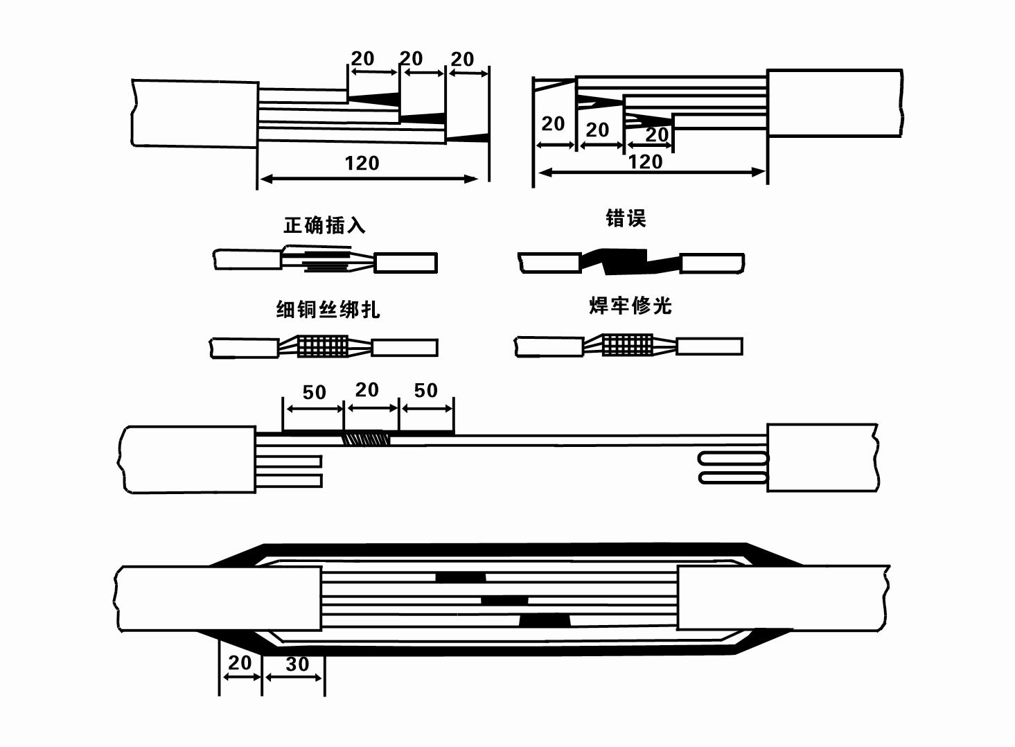
7. Cable joint, cut off a 120mm rubber sleeve from one end of the outgoing cable and the matching cable with an electrician's knifethen stagger the length of the three core wires in a stepped shape, peel off a 20mm copper core, scrape of the oxide layer on theoutside of the copper wire with a knife or sand cloth, and insert the two connected wire ends in palirs.
After tying the layer tightly with fine copper wire, solder it thoroughly and firmly, and sand of any. burrs on the surface. Then, forthe three joints, use polyvester insulation tape to wrap them in a semi stacked manner for three lavers. Wrap the two ends of thewrapping layer tightywith nyion thread,and then use a semi stacked method to wrap the tape for three layers. Wrap the outellayer with high-pressure insulation tape for three layers. Finally, fold the threestrands together and repeatedly wrap them for fivelayers with high-pressure tape. Each layer must be tightly tied, and the interlayer joints must be tight and fimm to prevent water frompenetrating and damaging the insulation, After wrapping, soak in water at room temperature of 20 ’c for 12 hours, and measurethe insulation resistance with a shaking table, which should not be less than 100M Ω
Det vedhæftede kabelledningsdiagram er som følger:
8. Brug et multimeter til at kontrollere, om de trefasede ledninger er tilsluttet, og om DC-modstanden er tilnærmelsesvis afbalanceret.
9. Check whether the circuit and transformer capacity are overloaded, and then connect the overload protection switch or starting equipment. See Table 2 for specific models, and then
Pour a bucket of water into the water pump from the water pump outlet to lubricate the rubber bearings in the pump, and then place the submersible electric pump upright and steady.
Start (no more than one second) and check whether the steering direction is consistent with the steering sign. If not, swap any two connectors of the three-phase cable.
Then install the filter and prepare to go down the well. If used in special occasions (such as ditches, ditches, rivers, ponds, ponds, etc.), the electric pump must be reliably grounded.
(2) Installationsudstyr og værktøjer:
1. Et par løftekæder til mere end to tons.
2. Et stativ med en lodret højde på ikke mindre end fire meter.
3. To hængereb (wirereb), der kan bære en vægt på mere end et ton (kan bære vægten af et komplet sæt vandpumper).
4. Installer to par klemmer (skinne).
5. Skruenøgler, hamre, skruetrækkere, elektrisk værktøj og instrumenter mv.
(3) Installation af elektrisk pumpe:
1. Installationsdiagrammet for den dyk-elektriske pumpe er vist i figur 2. De specifikke installationsdimensioner er vist i Tabel 3 "Liste over installationsdimensioner for den dyk-elektriske pumpe".
2. Dykpumper med en løftehøjde på mindre end 30 meter kan hejses direkte ned i brønden ved hjælp af slanger og ståltove eller andre hamperove, der kan bære den fulde vægt af hele maskinen, vandrør og vand i rørene.
3. Pumper med en løftehøjde på mere end 30 meter anvender stålrør, og installationsrækkefølgen er som følger:
①Use a clamp to clamp the upper end of the water pump part (the motor and water pump have been connected at this time), lift it with a hanging chain, and slowly tie it into the well until
Put the clamp on the wellhead and remove the hanging chain.
② Use another pair of clamps to clamp a pipe, lift it with a hanging chain 15 cm away from the flange, and lower it slowly. Between pipe flange and pump flange
Put the rubber pad in place and tighten the pipe and pump evenly with bolts, nuts and spring washers.
③ Løft dykpumpen lidt, fjern klemmen på den øverste ende af vandpumpen, bind kablet fast til vandrøret med et plastikbånd, og bind det langsomt ned, indtil klemmen er placeret ved brøndhovedet.
④Brug samme metode til at binde alle vandrør i brønden.
⑤ Efter at udløbskablet er tilsluttet kontrolkontakten, tilsluttes det til den trefasede strømforsyning.
(4) Ting at bemærke under installationen:
1. If a jamming phenomenon is found during the pumping process, turn or pull the water pipe to overcome the jamming point. If various measures still do not work, please
Do not force the pump down to avoid damage to the submersible electric pump and the well.
2. Under installationen skal der placeres en gummipude ved flangen på hvert rør og strammes jævnt.
3. Når vandpumpen sænkes ned i brønden, skal den placeres i midten af brøndrøret for at forhindre pumpen i at køre mod brøndvæggen i lang tid, hvilket får pumpen til at vibrere og motoren til at feje og brænde .
4. Bestem dybden af vandpumpen til bunden af brønden i henhold til brøndens flydende sand- og siltforhold. Begrav ikke pumpen i mudderet. Afstanden fra vandpumpen til bunden af brønden er generelt ikke mindre end 3 meter (se figur 2).
5. Vandpumpens vandindgangsdybde bør ikke være mindre end 1-1,5 meter fra den dynamiske vandstand til vandindløbsknuden (se figur 2). Ellers kan vandpumpens lejer let blive beskadiget.
6. Vandpumpens løft må ikke være for lavt. Ellers skal der installeres en skydeventil på brøndhovedets vandrørledning for at styre pumpeflowet ved det nominelle flowpunkt for at forhindre, at motoren bliver overbelastet og brændt ud på grund af store flowhastigheder.
7. Når vandpumpen kører, skal vandudgangen være kontinuerlig og jævn, strømmen skal være stabil (under nominelle arbejdsforhold, generelt ikke mere end 10% af nominel strøm), og der bør ikke være vibrationer eller støj. Hvis der er noget unormalt, skal maskinen standses for at finde ud af årsagen og eliminere den.
8. Når du installerer, skal du være opmærksom på indstillingen af motorens jordledning (se figur 2). Når vandrøret er et stålrør, før det fra brøndhovedklemmen; når vandrøret er et plastikrør, før det fra jordingsmærket på den elektriske pumpe.
- 1. Efter at dykpumpen er installeret, skal du kontrollere isolationsmodstanden og trefaset ledning fra kontakten igen, kontrollere om instrumentet og tilslutningen af startudstyret er forkert, hvis der ikke er noget problem, kan prøvemaskinen startes, og observer, om instrumentets indikatoraflæsninger overstiger den nominelle spænding og strøm, der er angivet på typeskiltet efter start, og observer, om pumpen har støj- og vibrationsfænomen, og sættes i drift, hvis alt er normalt.
- 2. Efter den første drift af pumpen i fire timer, skal motoren lukkes ned for hurtigt at teste den termiske isolationsmodstand, og dens værdi bør ikke være mindre end 0,5 megaohm.
- 3. Efter at pumpen er lukket ned, skal den startes efter fem minutter for at forhindre, at vandsøjlen i røret flyder fuldstændigt tilbage og forårsager for stor motorstrøm og udbrænding.
- 4. Efter at pumpen er sat i normal drift, for at forlænge dens levetid, er det nødvendigt at kontrollere, om forsyningsspændingen, arbejdsstrømmen og isolationsmodstanden er normale regelmæssigt. Hvis følgende forhold findes, skal pumpen lukkes ned med det samme for at fejlfinde.
- 1 In the rated condition, the current exceeds 20%.
- 2 Den dynamiske vandstand falder til vandindløbssektionen, hvilket forårsager intermitterende vand.
- 3 Dykpumpen har kraftige vibrationer eller støj.
- 4 Forsyningsspændingen er lavere end 340 volt.
- 5 En sikring er brændt ud.
- 6 Vandforsyningsrøret er beskadiget.
- 7 The motor's thermal insulation resistance is lower than 0.5 megaohm.
- Unit disassembly:
- 1.Untie the cable tie, remove the pipeline part, and remove the wire plate.
- 2.screw down the water bolt, put the water in the motor chamber.
- 3.remove the filter, loose the fixed screw on the coupling to fix the motor shaft.
- 4.screw down the bolt connecting the water inlet section with the motor, and separate the pump from the motor (pay attention to the unit cushion when separating, to prevent the bending of the pump shaft)
- 5.the disassembly sequence of the pump is: (see figure 1) water inlet section, impeller, diversion shell, impeller...... check valve body, when removing the impeller, use special tools to loosen the conical sleeve of the fixed impeller first, and avoid bending and bruising the pump shaft in the process of disassembly.
- 6.the disassembly process of the motor is: (see figure 1) place the motor on the platform, and remove the nuts, base, shaft head locking nut, thrust plate, key, lower guide bearing seat and double head bolt from the bottom of the motor in turn, and then take out the rotor (pay attention not to damage the wire package) and finally remove the connecting section and upper guide bearing seat.
- 7.unit assembly: before assembly, the rust and dirt of the parts should be cleaned, and the mating surface and fasteners coated with sealant, and then assembled in the opposite order of disassembly (the motor shaft moves up and down after assembly for about one millimeter), after assembly, the coupling should be flexible, and then the filter screen test machine. Submersible pumps shall be taken out of the well for dismantling and maintenance according to Article 5 after a year of operation, or less than a year of operation but two years of diving time, and the worn parts shall be replaced.
This product is an efficient and durable submersible electric pump, suitable for a variety of environments and applications.In order to ensure the long-term use and stable performance of the product, we suggest that users pay special attention to drying the water in the motor cavity in winter to avoid freezing; in addition, the cable is coiled and tied, and properly stored in an environment without corrosive substances and gases, with a temperature below 40 °C. If the product is not used for a long time, attention should be paid to rust prevention treatment to ensure the life cycle and performance of the product.Whether for industrial use or for home use, this submersible electric pump can provide you with reliable pump service.
-
- Løbehjul
- Skaftbøsning
- Skaftbøsning af gummi
-
Pakning
01 Dyb brønds vandindtag
02 Vandforsyning i højhuse
03 bjergvandforsyning
04 tårnvand
05 Landbrugsvanding
06 havevanding
07 flodvandindtag
08 brugsvand


