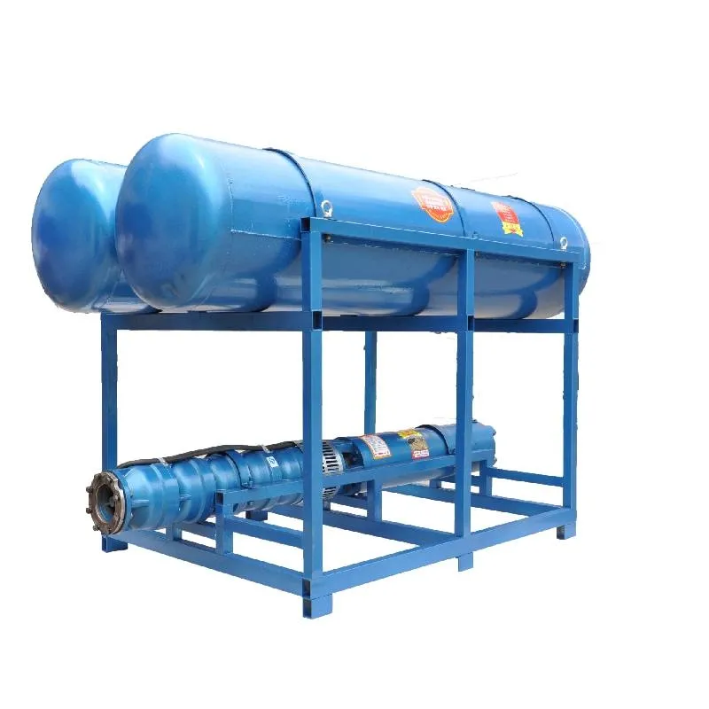
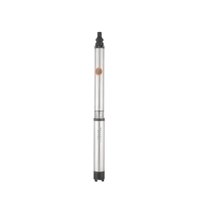
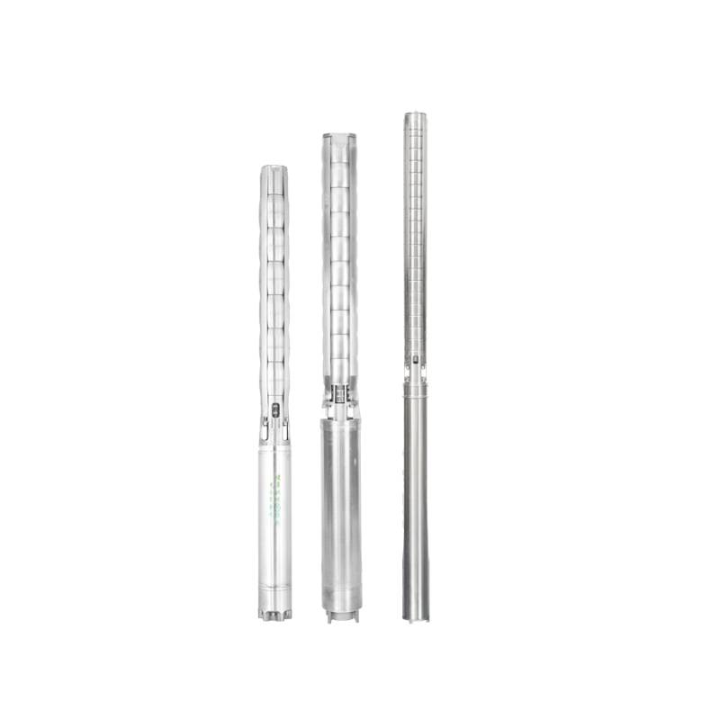
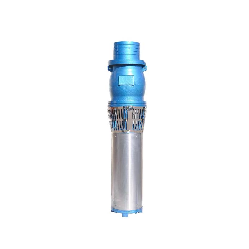
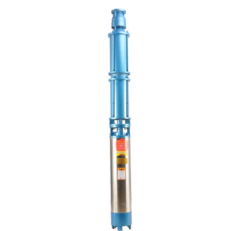
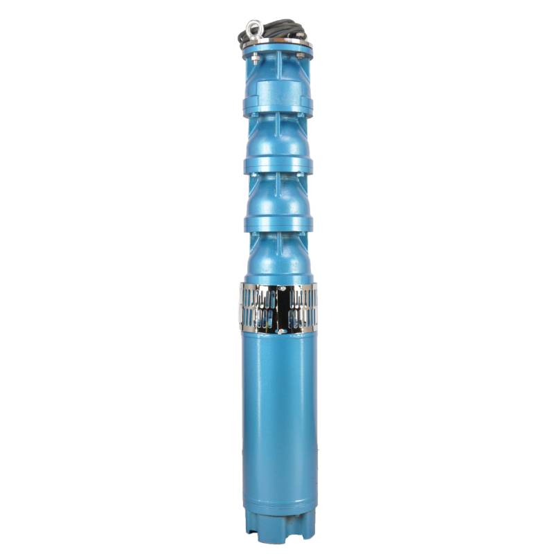
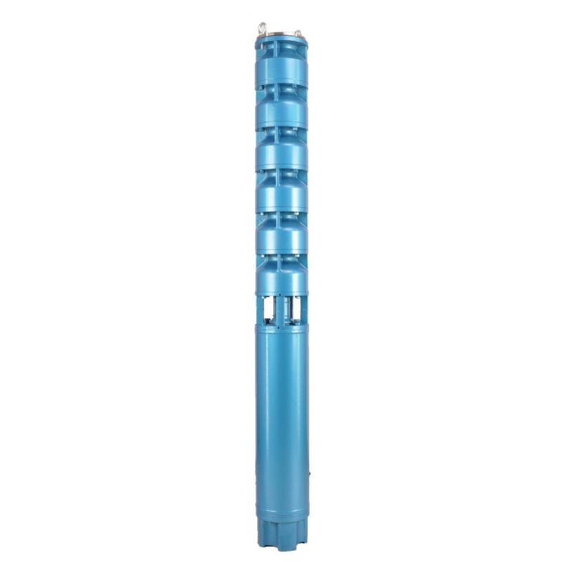
Frequency conversion winding design, ensure the motor in 1HZ-50HZ long-term stable conversion operation. Energy saving, longer service life.
1, nutrado: trifaza AC 380V (toleremo + / - 5%), 50HZ (toleremo + / - 1%).
2, akvokvalito:
(1) water temperature is not higher than 20 °C;
(2) enhavo de solidaj malpuraĵoj (masa proporcio) ne estas pli granda ol 0,01%;
(3) PH-valoro (pH) 6,5-8,5;
(4) enhavo de hidrogena sulfido ne estas pli granda ol 1,5 mg/L;
(5) klorida jona enhavo ne estas pli granda ol 400mg/L.
3, la motoro estas fermita aŭ akvo-plena malseka strukturo, antaŭ ol uzi la submergebla motora kavo devas esti plena de pura akvo, por malhelpi falsan plenan, kaj poste streĉu la akvon injekton, aerliberigo-rigliloj, alie ne rajtas uzi
4, subakvigebla pumpilo devas esti tute mergita en la akvon, la plonĝa profundo ne estas pli granda ol 70m, la fundo de la subakvigebla pumpilo de la fundo de la puto ne estas malpli ol 3m.
5, la puto akvofluo devus povi renkonti la mergebla pumpilo akvo eligo kaj kontinua operacio, la submergebla pumpilo akvo eligo devus esti kontrolita je 0,7 - 1,2 fojojn la taksita fluo.
6, la puto estu rekta, la subakvigebla pumpilo ne povas esti uzata aŭ forĵetita, nur vertikala uzo.
7, la subakvigebla pumpilo devas esti kongrua kun la kablo laŭ la postuloj, kaj la ekstera superŝarĝa protekta aparato. 8, la pumpilo estas strikte malpermesita sen akvo senŝarĝa testa maŝino
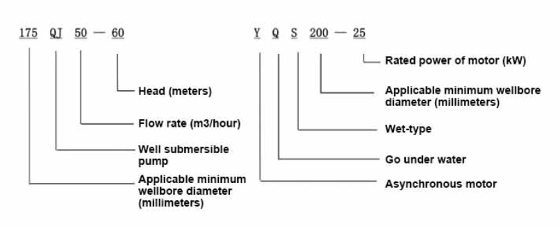
| Modelo | Fluo (m3/h) | Kapo (m) |
Rotating speed(change/point) | Akvopumpilo(%) | Elirejo diametro (mm) |
Aplika bone diametro (mm) |
Taksita potenco (KW) |
Rated voltage(V) | Ratedcurrent(A) | Motorefikeco (%) | power factorcosφ | Unuo Radiala Maksimuma grandeco (mm) |
Rimarko | |||||||||
| 125QJ5-34 | 5 | 34 | 2850 | 53 | 40 | 125supre | 1.5 | 380 | 4.23 | 70.0 | 0.77 | 118 | ||||||||||
| 125QJ5-51 | 51 | 2.2 | 6.03 | 72.0 | 0.77 | |||||||||||||||||
| 125QJ5-68 | 68 | 3 | 8.01 | 73.0 | 0.78 | |||||||||||||||||
| 125QJ5-85 | 85 | 4 | 10.53 | 74.0 | 0.78 | |||||||||||||||||
| 125QJ5-102 | 102 | 5.5 | 14.1 | 75.0 | 0.79 | |||||||||||||||||
| 125QJ5-119 | 119 | 5.5 | 14.1 | 75.0 | 0.79 | |||||||||||||||||
| 125QJ10-24 | 10 | 24 | 2850 | 60 | 50 | 125supre | 1.5 | 380 | 4.23 | 70.0 | 0.77 | 118 | ||||||||||
| 125QJ10-32 | 32 | 2.2 | 6.03 | 72.0 | 0.77 | |||||||||||||||||
| 125QJ10-48 | 48 | 3 | 8.01 | 73.0 | 0.78 | |||||||||||||||||
| 125QJ10-56 | 56 | 4 | 10.53 | 74.0 | 0.78 | |||||||||||||||||
| 125QJ10-72 | 72 | 5.5 | 14.1 | 75.0 | 0.79 | |||||||||||||||||
| 125QJ10-80 | 80 | 5.5 | 14.1 | 75.0 | 0.79 | |||||||||||||||||
| 125QJ10-104 | 104 | 7.5 | 19.0 | 76.0 | 0.79 | |||||||||||||||||
| 125QJ10-120 | 10 | 120 | 2850 | 60 | 50 | 125supre | 7.5 | 380 | 19.0 | 76.0 | 0.79 | 118 | ||||||||||
| 125QJ10-136 | 136 | 9.2 | 22.7 | 77.0 | 0.8 | |||||||||||||||||
| 125QJ15-36 | 15 | 36 | 2850 | 63 | 50 | 125supre | 2.2 | 380 | 6.03 | 72.0 | 0.77 | 118 | ||||||||||
| 125QJ15-39 | 39 | 3 | 8.01 | 73.0 | 0.78 | |||||||||||||||||
| 125QJ15-46 | 46 | 4 | 10.53 | 74.0 | 0.78 | |||||||||||||||||
| 125QJ15-52 | 52 | 4 | 10.53 | 74.0 | 0.78 | |||||||||||||||||
| 125QJ15-59 | 59 | 5.5 | 14.1 | 75.0 | 0.79 | |||||||||||||||||
| 125QJ15-65 | 65 | 5.5 | 14.1 | 75.0 | 0.79 | |||||||||||||||||
| 125QJ15-78 | 78 | 7.5 | 19.0 | 76.0 | 0.79 | |||||||||||||||||
| 125QJ15-91 | 91 | 7.5 | 19.0 | 76.0 | 0.79 | |||||||||||||||||
| 125QJ15-104 | 104 | 9.2 | 22.7 | 77.0 | 0.8 | |||||||||||||||||
| 125QJ20-16 | 20 | 16 | 2850 | 64 | 50 | 125supre | 2.2 | 380 | 6.03 | 72.0 | 0.77 | 118 | ||||||||||
| 125QJ20-24 | 24 | 3 | 8.01 | 73.0 | 0.78 | |||||||||||||||||
| 125QJ20-32 | 32 | 4 | 10.53 | 74.0 | 0.78 | |||||||||||||||||
| 125QJ20-40 | 40 | 4 | 10.53 | 74.0 | 0.78 | |||||||||||||||||
| 125QJ20-48 | 48 | 5.5 | 14.1 | 75.0 | 0.79 | |||||||||||||||||
| 125QJ20-56 | 56 | 5.5 | 14.1 | 75.0 | 0.79 | |||||||||||||||||
| 125QJ20-64 | 64 | 7.5 | 19.0 | 76.0 | 0.79 | |||||||||||||||||
| 125QJ20-72 | 72 | 7.5 | 19.0 | 76.0 | 0.79 | |||||||||||||||||
| 125QJ20-80 | 80 | 9.2 | 22.7 | 77.0 | 0.8 | |||||||||||||||||
| 125QJ25-12 | 25 | 12 | 2850 | 64 | 65 | 125supre | 2.2 | 380 | 6.03 | 72.0 | 0.77 | 118 | ||||||||||
| 125QJ25-18 | 18 | 3 | 8.01 | 73.0 | 0.78 | |||||||||||||||||
| 125QJ25-24 | 24 | 4 | 10.53 | 74.0 | 0.78 | |||||||||||||||||
| 125QJ25-30 | 30 | 4 | 10.53 | 74.0 | 0.78 | |||||||||||||||||
| 125QJ25-36 | 36 | 5.5 | 14.1 | 75.0 | 0.79 | |||||||||||||||||
| 125QJ25-48 | 48 | 7.5 | 19.0 | 76.0 | 0.79 | |||||||||||||||||
| 125QJ25-60 | 60 | 9.2 | 22.7 | 77.0 | 0.8 | |||||||||||||||||
| 125QJ32-24 | 32 | 24 | 2850 | 64 | 80 | 125supre | 4 | 380 | 10.53 | 74.0 | 0.78 | 118 | ||||||||||
| 125QJ32-30 | 30 | 5.5 | 14.1 | 75.0 | 0.79 | |||||||||||||||||
| 125QJ32-42 | 42 | 7.5 | 19.0 | 76.0 | 0.79 | |||||||||||||||||
| 125QJ32-54 | 54 | 9.2 | 22.7 | 77.0 | 0.8 | |||||||||||||||||
| 125QJ5-240 | 5 | 240 | 2850 | 40 | 125supre | 11 | 380 | 26.28 | 118 | |||||||||||||
| 125QJ5-280 | 280 | 13 | 30.87 | |||||||||||||||||||
| 125QJ5-320 | 320 | 15 | 35.62 | |||||||||||||||||||
| 125QJ10-180 | 10 | 180 | 2850 | 50 | 125supre | 11 | 380 | 26.28 | 118 | |||||||||||||
| 125QJ10-210 | 210 | 13 | 30.87 | |||||||||||||||||||
| 125QJ10-240 | 240 | 15 | 35.62 | |||||||||||||||||||
| 125QJ15-120 | 15 | 120 | 2850 | 50 | 125supre | 11 | 380 | 26.28 | 118 | |||||||||||||
| 125QJ15-142 | 142 | 13 | 30.87 | |||||||||||||||||||
| 125QJ15-162 | 162 | 15 | 35.62 | |||||||||||||||||||
| 125QJ20-100 | 20 | 100 | 2850 | 50 | 125supre | 11 | 380 | 26.28 | 118 | |||||||||||||
| 125QJ20-120 | 120 | 13 | 30.87 | |||||||||||||||||||
| 125QJ20-136 | 136 | 15 | 35.62 | |||||||||||||||||||
| 125QJ25-82 | 25 | 82 | 2850 | 65 | 125supre | 11 | 380 | 26.28 | 118 | |||||||||||||
| 125QJ25-97 | 97 | 13 | 30.87 | |||||||||||||||||||
| 125QJ25-110 | 110 | 15 | 35.62 | |||||||||||||||||||
| 125QJ32-68 | 32 | 68 | 2850 | 80 | 125supre | 11 | 380 | 26.28 | 118 | |||||||||||||
| 125QJ32-80 | 80 | 13 | 30.87 | |||||||||||||||||||
| 125QJ32-92 | 92 | 15 | 35.62 | |||||||||||||||||||
| 125QJ40-46 | 40 | 46 | 2850 | 80 | 125supre | 11 | 380 | 26.28 | 118 | |||||||||||||
| 125QJ40-54 | 54 | 13 | 30.87 | |||||||||||||||||||
| 125QJ40-62 | 62 | 15 | 35.62 | |||||||||||||||||||
The well submersible pump is a pump suitable for clear water. It is strictly prohibited to dig new wells and pump out mud and sand. The voltage grade of the well pump is 380V/50HZ, and other voltage grades of the submersible motor need to be customized. Underground cables must be waterproof cables and must be equipped with starting equipment, such as distribution box, etc. The starting equipment should have common motor comprehensive protection functions, such as short circuit overload protection, phase loss protection, undervoltage protection, grounding protection and idling protection, etc. In abnormal cases, the protective device should be tripped in time. When installing and using the pump, it must be firmly grounded. It is prohibited to push and pull the switch when the hands and feet are wet. The power supply must be cut off before installing and maintaining the pump. An obvious "anti-electric shock" sign must be set up where the pump is used. Before going down the well or installing the motor, the inner cavity must be filled with distilled water or non-corrosive clean cold water, and the water injection/drainage bolts must be tightened. Fill the pump with water for ground test to lubricate the rubber bearings. The instant start time shall not exceed one second to check whether the direction is correct and consistent with the direction indication. Be sure to pay attention to safety when placing the pump upright to prevent overturning and causing injury. Strictly in accordance with the provisions of the pump lift and flow range of use, to prevent the pump flow at low lift or excessive pull at high lift, resulting in extreme wear of thrust bearings and other components, resulting in motor overload burn. After the pump into the well, the insulation resistance between the motor and the ground shall be measured, which shall not be less than 100MΩ. After the start, observe the voltage and current regularly, and check the motor winding insulation, to see if it meets the requirements; if the pump storage temperature is below the freezing point, the water in the motor cavity should be discharged, so as to avoid the water in the motor cavity freezing and damaging the motor due to low temperature.
La ĉefaj trajtoj de la produkto inkluzivas:
1.The motor is a water-loaded wet submersible three-phase asynchronous motor,and the motor cavity is filled with clean water for cooling the motor and lubricating the bearing.The regulating diaphragm at the bottom of the motor is used to adjust the expansion and contraction pressure difference inside and outside the body caused by the temperature rise of the motor.
2.In order to prevent the sand particles in the well water from entering the motor,two oil seals are installed at the extension end of the motor shaft,and the sand ring is installed to form a sand prevention structure.
3.In order to prevent the pump shaft from jumping when starting,the pump shaft is connected with the motor shaft through a coupling,and the thrust bearing is installed at the bottom of the motor.
4.The lubrication of the motor and the pump bearing is water lubrication.
5.The stator winding of the motor adopts high-quality submersible motor winding wire,with excellent insulation performance.
6.The pump is designed by computer CAD,with simple structure and excellent technical performance.

(1) Preparado antaŭ instalado:
1. Kontrolu ĉu la subakvigebla pumpilo plenumas la uzajn kondiĉojn kaj amplekson specifitajn en la manlibro.
2. Uzante pezan objekton kun diametro egala al la maksimuma ekstera diametro de la subakvigebla pumpilo, mezuru ĉu la interna diametro de la puttruo povas konveni al la subakvigebla pumpilo, kaj mezuru ĉu la putoprofundo plenumas la instalajn postulojn.
3. Kontrolu ĉu la puttruo estas pura kaj ĉu la putakvo estas malklara. Neniam uzu subakvigan elektran pumpilon por lavi la koton kaj sablan akvon por eviti trofruan damaĝon al la subakvigebla elektra pumpilo.
4. Kontrolu ĉu la pozicio de la welhead instala krampo taŭgas kaj ĉu ĝi povas elteni la kvaliton de la tuta unuo.
5. Kontrolu ĉu la subakvigeblaj pumpiloj estas kompletaj kaj instalitaj konvene laŭ la aro-diagramo en la manlibroForigu la filtrilan ekranon kaj turnu la kuplilon por vidi ĉu ĝi turniĝas flekseble.
6. Malŝraŭbi la akvoŝraŭbon kaj plenigi la motoran kavon per pura, ne koroda akvo (notu. nepre plenigu ĝin), tiam streĉu la akvoŝraŭbon. Post 12 horoj da akva injekto, la izolaj rezisto de la motoro ne devus esti malpli ol 150M Q kiam mezurita kun 500V skuanta tablo.
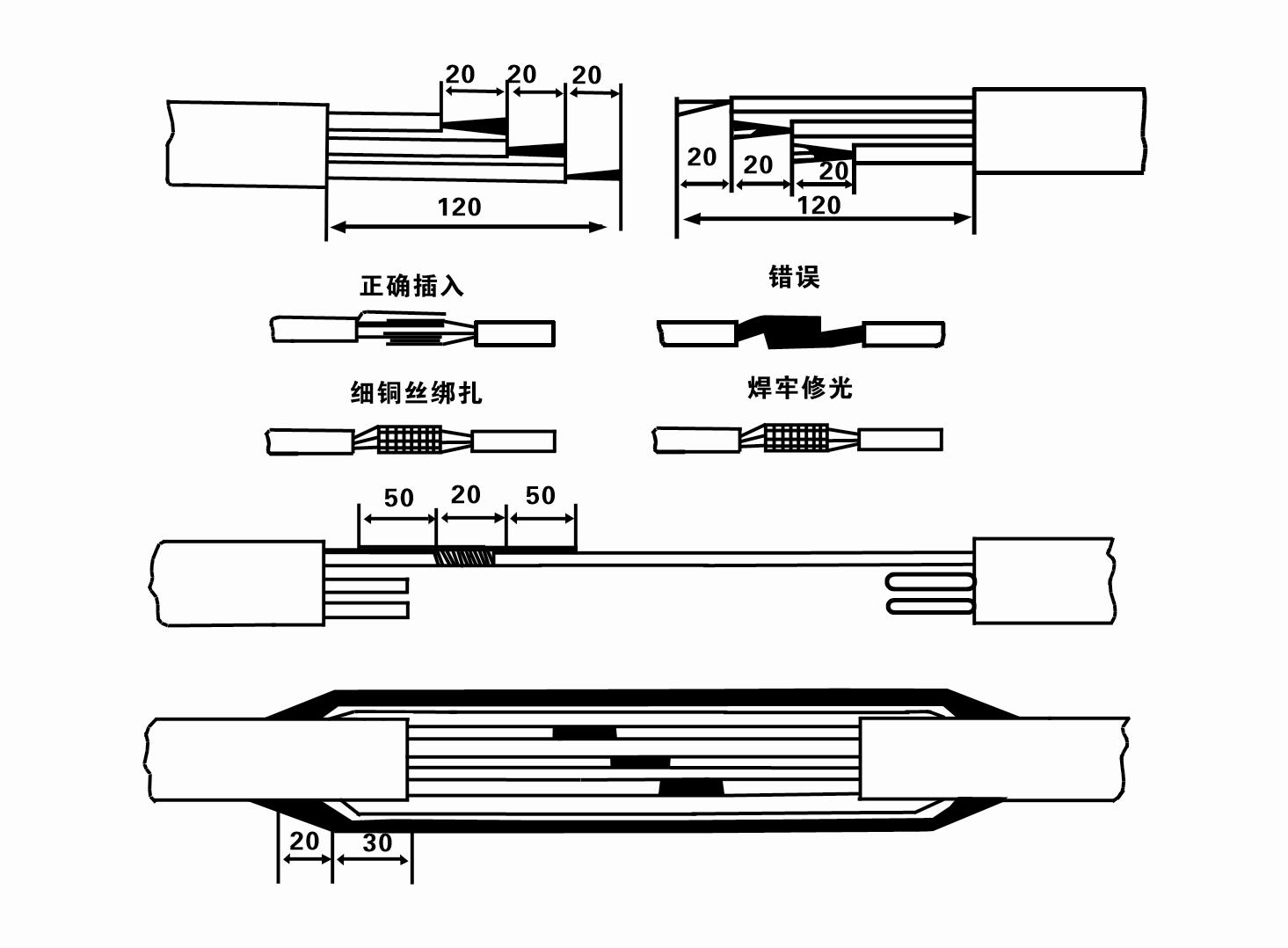
7. Cable joint, cut off a 120mm rubber sleeve from one end of the outgoing cable and the matching cable with an electrician's knifethen stagger the length of the three core wires in a stepped shape, peel off a 20mm copper core, scrape of the oxide layer on theoutside of the copper wire with a knife or sand cloth, and insert the two connected wire ends in palirs.
After tying the layer tightly with fine copper wire, solder it thoroughly and firmly, and sand of any. burrs on the surface. Then, forthe three joints, use polyvester insulation tape to wrap them in a semi stacked manner for three lavers. Wrap the two ends of thewrapping layer tightywith nyion thread,and then use a semi stacked method to wrap the tape for three layers. Wrap the outellayer with high-pressure insulation tape for three layers. Finally, fold the threestrands together and repeatedly wrap them for fivelayers with high-pressure tape. Each layer must be tightly tied, and the interlayer joints must be tight and fimm to prevent water frompenetrating and damaging the insulation, After wrapping, soak in water at room temperature of 20 ’c for 12 hours, and measurethe insulation resistance with a shaking table, which should not be less than 100M Ω
La alkroĉita kablokabla procezo-diagramo estas kiel sekvas:
8. Uzu multimetron por kontroli ĉu la trifazaj dratoj estas konektitaj kaj ĉu la DC-rezisto estas proksimume ekvilibra.
9. Check whether the circuit and transformer capacity are overloaded, and then connect the overload protection switch or starting equipment. See Table 2 for specific models, and then
Pour a bucket of water into the water pump from the water pump outlet to lubricate the rubber bearings in the pump, and then place the submersible electric pump upright and steady.
Start (no more than one second) and check whether the steering direction is consistent with the steering sign. If not, swap any two connectors of the three-phase cable.
Then install the filter and prepare to go down the well. If used in special occasions (such as ditches, ditches, rivers, ponds, ponds, etc.), the electric pump must be reliably grounded.
(2) Instalaj ekipaĵoj kaj iloj:
1. Unu paro da levaj ĉenoj por pli ol du tunoj.
2. Tripiedo kun vertikala alteco ne malpli ol kvar metroj.
3. Du pendantaj ŝnuroj (drataj ŝnuroj), kiuj povas porti pezon de pli ol unu tuno (povas porti la pezon de kompleta aro da akvopumpiloj).
4. Instalu du parojn da krampoj (splitaĵoj).
5. Ŝlosiloj, marteloj, ŝraŭbturniloj, elektraj iloj kaj instrumentoj, ktp.
(3) Instalado de elektra pumpilo:
1. La instala diagramo de la subakvigebla elektra pumpilo estas montrita en Figuro 2. La specifaj instalaj dimensioj estas montritaj en Tabelo 3 "Listo de Instalaj Dimensioj de la Submergebla Elektra Pumpilo".
2. Submergeblaj elektraj pumpiloj kun kapo malpli ol 30 metroj povas esti levitaj rekte en la puton per hosoj kaj drataj ŝnuroj aŭ aliaj kanabaj ŝnuroj, kiuj povas porti la plenan pezon de la tuta maŝino, akvotuboj kaj akvo en la tuboj.
3. Pumpiloj kun kapo de pli ol 30 metroj uzas ŝtalajn tubojn, kaj la instala sekvenco estas jena:
①Use a clamp to clamp the upper end of the water pump part (the motor and water pump have been connected at this time), lift it with a hanging chain, and slowly tie it into the well until
Put the clamp on the wellhead and remove the hanging chain.
② Use another pair of clamps to clamp a pipe, lift it with a hanging chain 15 cm away from the flange, and lower it slowly. Between pipe flange and pump flange
Put the rubber pad in place and tighten the pipe and pump evenly with bolts, nuts and spring washers.
③ Levu la subakvigeblan pumpilon iomete, forigu la krampon sur la supra fino de la akvopumpilo, ligu la kablon firme al la akvotubo per plasta bendo, kaj malrapide ligu ĝin malsupren ĝis La krampo estas metita ĉe la puto.
④Uzu la saman metodon por ligi ĉiujn akvotubojn en la puton.
⑤Post kiam la elkonduka kablo estas konektita al la kontrolŝaltilo, ĝi estas konektita al la trifaza nutrado.
(4) Aferoj notindaj dum instalado:
1. If a jamming phenomenon is found during the pumping process, turn or pull the water pipe to overcome the jamming point. If various measures still do not work, please
Do not force the pump down to avoid damage to the submersible electric pump and the well.
2. Dum instalado, kaŭĉuka kuseneto devas esti metita ĉe la flanĝo de ĉiu tubo kaj streĉita egale.
3. Kiam la akvopumpilo estas malaltigita en la puton, ĝi devas esti metita en la mezon de la putotubo por malhelpi la pumpilon kuri kontraŭ la putmuro dum longa tempo, kaŭzante la pumpilon vibri kaj la motoro balai kaj bruli. .
4. Determini la profundon de la akvopumpilo al la fundo de la puto laŭ la fluantaj sablo kaj siltaj kondiĉoj de la puto. Ne enterigu la pumpilon en la koto. La distanco de la akvopumpilo ĝis la fundo de la puto estas ĝenerale ne malpli ol 3 metroj (vidu Figuro 2).
5. La akvo-enira profundo de la akvopumpilo devas esti ne malpli ol 1-1,5 metroj de la dinamika akvonivelo ĝis la akva enirnodo (vidu Figuro 2). Alie, la akvopumpilaj lagroj povas esti facile difektitaj.
6. La lifto de la akvopumpilo ne povas esti tro malalta. Alie, pordega valvo devas esti instalita sur la putokapa akvodukto por kontroli la pumpilfluon ĉe la taksita flupunkto por malhelpi la motoron esti troŝarĝita kaj forbrulita pro grandaj flukvantoj.
7. Kiam la akvopumpilo funkcias, la akvoproduktado devas esti kontinua kaj eĉ, la fluo estu stabila (sub taksitaj laborkondiĉoj, ĝenerale ne pli ol 10% de la taksita kurento), kaj ne estu vibro aŭ bruo. Se estas ia anomalio, la maŝino devas esti haltigita por ekscii la kaŭzon kaj forigi ĝin.
8. Kiam vi instalas, atentu la agordon de la motora tera drato (vidu Figuro 2). Kiam la akvotubo estas ŝtala tubo, konduku ĝin de la putkapa krampo; kiam la akvotubo estas plasta tubo, konduku ĝin de la surgrunda marko de la elektra pumpilo.
- 1. Post kiam la subakvigebla pumpilo estas instalita, kontrolu la izolan reziston kaj trifazan kondukadon de la ŝaltilo denove, kontrolu ĉu la instrumento kaj la konekto de la starta ekipaĵo estas malĝustaj, se ne estas problemo, la prova maŝino povas esti komencita, kaj observu ĉu la indikilaj legaĵoj de la instrumento superas la taksitan tensio kaj fluon specifita sur la nomplato post la komenco, kaj observu ĉu la pumpilo havas bruon kaj vibran fenomenon, kaj ekfunkciigas se ĉio estas normala.
- 2.Post la unua funkciado de la pumpilo dum kvar horoj, la motoro devas esti malŝaltita por testi la termizolan reziston rapide, kaj ĝia valoro ne estu malpli ol 0,5 megaohm.
- 3.Post kiam la pumpilo estas malŝaltita, ĝi devas esti komencita post kvin minutoj por malhelpi la akvokolumnon en la tubo tute reflui kaj kaŭzi troan motoran kurenton kaj elĉerpiĝon.
- 4.Post kiam la pumpilo estas metita en normalan funkciadon, por plilongigi sian servan vivon, necesas kontroli ĉu la provizotensio, laborfluo kaj izolaj rezisto estas normalaj regule. Se la sekvaj kondiĉoj estas trovitaj, la pumpilo devus esti malŝaltita tuj por solvi problemojn.
- 1 In the rated condition, the current exceeds 20%.
- 2 La dinamika akvonivelo falas al la akvoflua sekcio, kaŭzante intermitan akvon.
- 3 La subakvigebla pumpilo havas severan vibradon aŭ bruon.
- 4 La tensio de provizado estas pli malalta ol 340 voltoj.
- 5 Fuzeo estas forbruligita.
- 6 La akvoproviza tubo estas difektita.
- 7 The motor's thermal insulation resistance is lower than 0.5 megaohm.
- Unit disassembly:
- 1.Untie the cable tie, remove the pipeline part, and remove the wire plate.
- 2.screw down the water bolt, put the water in the motor chamber.
- 3.remove the filter, loose the fixed screw on the coupling to fix the motor shaft.
- 4.screw down the bolt connecting the water inlet section with the motor, and separate the pump from the motor (pay attention to the unit cushion when separating, to prevent the bending of the pump shaft)
- 5.the disassembly sequence of the pump is: (see figure 1) water inlet section, impeller, diversion shell, impeller...... check valve body, when removing the impeller, use special tools to loosen the conical sleeve of the fixed impeller first, and avoid bending and bruising the pump shaft in the process of disassembly.
- 6.the disassembly process of the motor is: (see figure 1) place the motor on the platform, and remove the nuts, base, shaft head locking nut, thrust plate, key, lower guide bearing seat and double head bolt from the bottom of the motor in turn, and then take out the rotor (pay attention not to damage the wire package) and finally remove the connecting section and upper guide bearing seat.
- 7.unit assembly: before assembly, the rust and dirt of the parts should be cleaned, and the mating surface and fasteners coated with sealant, and then assembled in the opposite order of disassembly (the motor shaft moves up and down after assembly for about one millimeter), after assembly, the coupling should be flexible, and then the filter screen test machine. Submersible pumps shall be taken out of the well for dismantling and maintenance according to Article 5 after a year of operation, or less than a year of operation but two years of diving time, and the worn parts shall be replaced.
This product is an efficient and durable submersible electric pump, suitable for a variety of environments and applications.In order to ensure the long-term use and stable performance of the product, we suggest that users pay special attention to drying the water in the motor cavity in winter to avoid freezing; in addition, the cable is coiled and tied, and properly stored in an environment without corrosive substances and gases, with a temperature below 40 °C. If the product is not used for a long time, attention should be paid to rust prevention treatment to ensure the life cycle and performance of the product.Whether for industrial use or for home use, this submersible electric pump can provide you with reliable pump service.
-
- Impulsilo
- Ŝafta maniko
- Kaŭĉuka ŝafta maniko
-
Sigela ringo
01 Profunda puta akvokonsumado
02 Alta akvoprovizado
03 montara akvoprovizado
04 turo akvo
05 Agrikultura irigacio
06 ĝardeno irigacio
07 rivera akvopreno
08 hejma akvo


