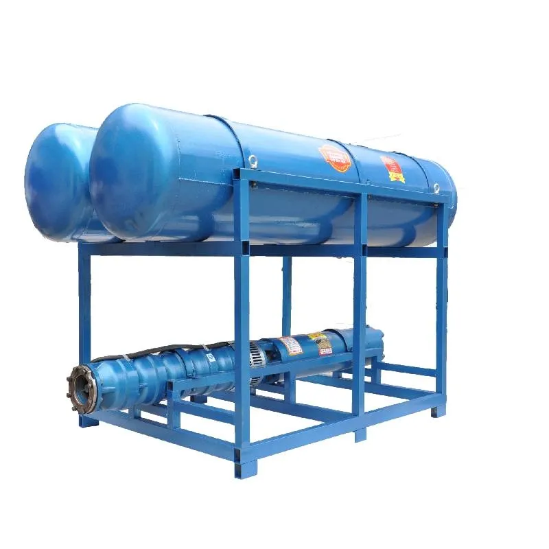
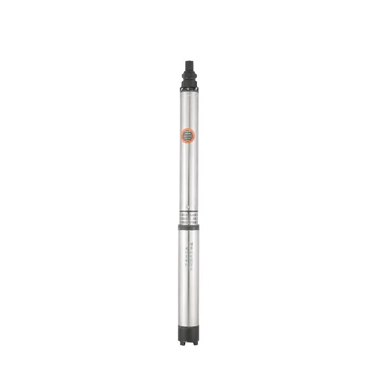
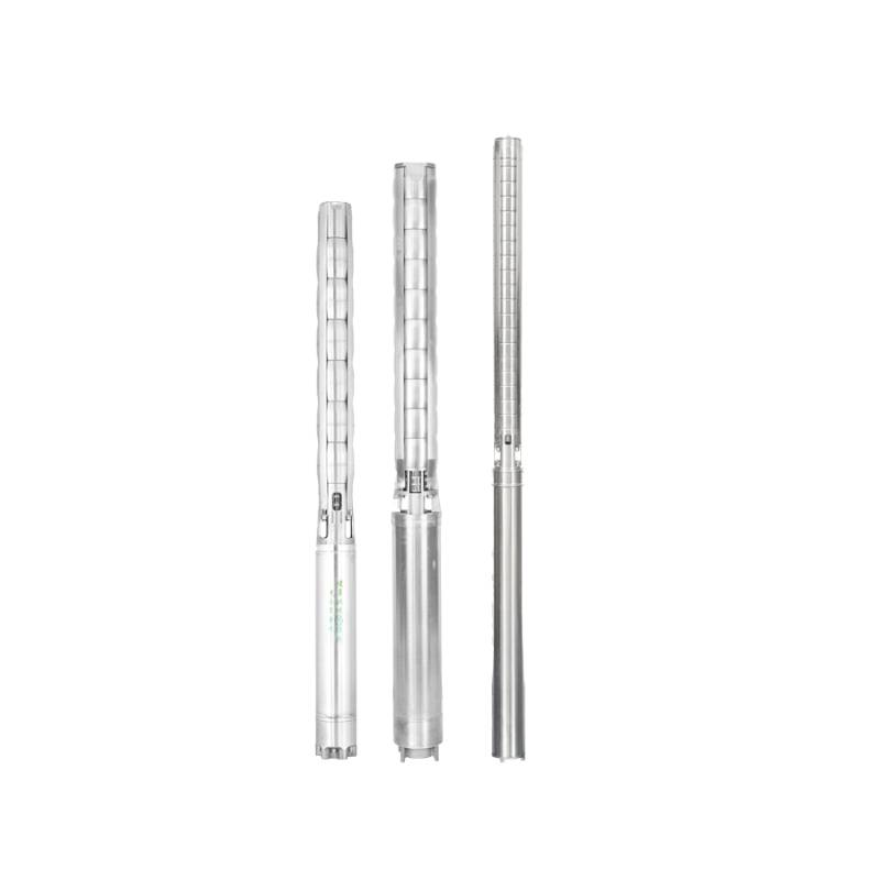
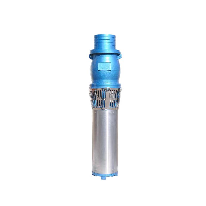
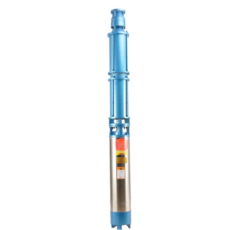
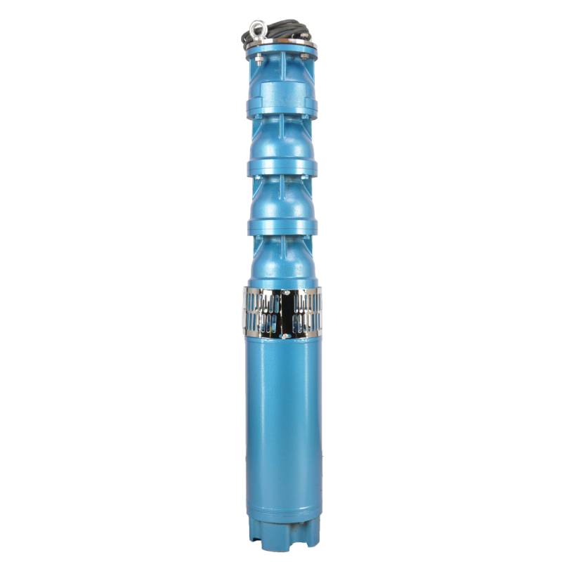
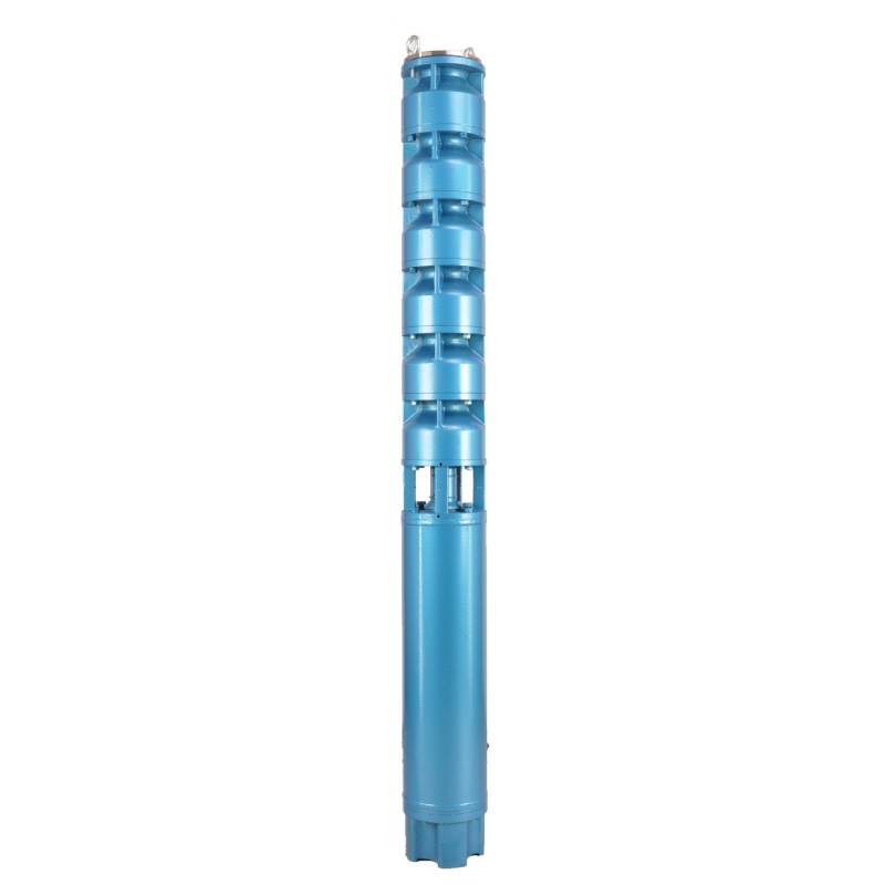
Frequency conversion winding design, ensure the motor in 1HZ-50HZ long-term stable conversion operation. Energy saving, longer service life.
1, strömförsörjning: trefas AC 380V (tolerans + / - 5%), 50HZ (tolerans + / - 1%).
2, vattenkvalitet:
(1) water temperature is not higher than 20 °C;
(2) innehållet av fasta föroreningar (massförhållande) inte är större än 0,01 %;
(3) PH-värde (pH) 6,5-8,5;
(4) vätesulfidhalten är inte större än 1,5 mg/L;
(5) Kloridjoninnehållet är inte större än 400 mg/L.
3, motorn är stängd eller vattenfylld våt struktur, innan användning måste den dränkbara motorns hålighet vara full av rent vatten, för att förhindra falsk full, och sedan dra åt vatteninsprutningen, luftutsläppsbultar, annars inte tillåtet att använda
4, dränkbar pump måste vara helt nedsänkt i vattnet, dykdjupet är inte större än 70m, botten av den dränkbara pumpen från botten av brunnen är inte mindre än 3m.
5, brunnsvattenflödet ska kunna möta den dränkbara pumpens vatteneffekt och kontinuerlig drift, bör den dränkbara pumpens vatteneffekt regleras till 0,7 - 1,2 gånger det nominella flödet.
6, brunnen ska vara rak, den dränkbara pumpen kan inte användas eller dumpas, endast vertikal användning.
7 måste den dränkbara pumpen matchas med kabeln enligt kraven och den externa överbelastningsskyddsanordningen. 8, pumpen är strängt förbjuden utan vatten utan belastning testmaskin
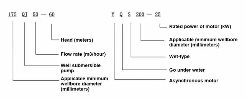
| Modell | Flöde (m3/h) | Huvud (m) |
Rotating speed(change/point) | Vattenpump(%) | Utlopp diameter (mm) |
Tillämplig väl diameter (mm) |
Betygsatt effekt (KW) |
Rated voltage(V) | Ratedcurrent(A) | Motoreffektivitet (%) | power factorcosφ | Enhet Radiell maximal storlek (mm) |
Anmärkning | |||||||||
| 125QJ5-34 | 5 | 34 | 2850 | 53 | 40 | 125ovan | 1.5 | 380 | 4.23 | 70.0 | 0.77 | 118 | ||||||||||
| 125QJ5-51 | 51 | 2.2 | 6.03 | 72.0 | 0.77 | |||||||||||||||||
| 125QJ5-68 | 68 | 3 | 8.01 | 73.0 | 0.78 | |||||||||||||||||
| 125QJ5-85 | 85 | 4 | 10.53 | 74.0 | 0.78 | |||||||||||||||||
| 125QJ5-102 | 102 | 5.5 | 14.1 | 75.0 | 0.79 | |||||||||||||||||
| 125QJ5-119 | 119 | 5.5 | 14.1 | 75.0 | 0.79 | |||||||||||||||||
| 125QJ10-24 | 10 | 24 | 2850 | 60 | 50 | 125ovan | 1.5 | 380 | 4.23 | 70.0 | 0.77 | 118 | ||||||||||
| 125QJ10-32 | 32 | 2.2 | 6.03 | 72.0 | 0.77 | |||||||||||||||||
| 125QJ10-48 | 48 | 3 | 8.01 | 73.0 | 0.78 | |||||||||||||||||
| 125QJ10-56 | 56 | 4 | 10.53 | 74.0 | 0.78 | |||||||||||||||||
| 125QJ10-72 | 72 | 5.5 | 14.1 | 75.0 | 0.79 | |||||||||||||||||
| 125QJ10-80 | 80 | 5.5 | 14.1 | 75.0 | 0.79 | |||||||||||||||||
| 125QJ10-104 | 104 | 7.5 | 19.0 | 76.0 | 0.79 | |||||||||||||||||
| 125QJ10-120 | 10 | 120 | 2850 | 60 | 50 | 125ovan | 7.5 | 380 | 19.0 | 76.0 | 0.79 | 118 | ||||||||||
| 125QJ10-136 | 136 | 9.2 | 22.7 | 77.0 | 0.8 | |||||||||||||||||
| 125QJ15-36 | 15 | 36 | 2850 | 63 | 50 | 125ovan | 2.2 | 380 | 6.03 | 72.0 | 0.77 | 118 | ||||||||||
| 125QJ15-39 | 39 | 3 | 8.01 | 73.0 | 0.78 | |||||||||||||||||
| 125QJ15-46 | 46 | 4 | 10.53 | 74.0 | 0.78 | |||||||||||||||||
| 125QJ15-52 | 52 | 4 | 10.53 | 74.0 | 0.78 | |||||||||||||||||
| 125QJ15-59 | 59 | 5.5 | 14.1 | 75.0 | 0.79 | |||||||||||||||||
| 125QJ15-65 | 65 | 5.5 | 14.1 | 75.0 | 0.79 | |||||||||||||||||
| 125QJ15-78 | 78 | 7.5 | 19.0 | 76.0 | 0.79 | |||||||||||||||||
| 125QJ15-91 | 91 | 7.5 | 19.0 | 76.0 | 0.79 | |||||||||||||||||
| 125QJ15-104 | 104 | 9.2 | 22.7 | 77.0 | 0.8 | |||||||||||||||||
| 125QJ20-16 | 20 | 16 | 2850 | 64 | 50 | 125ovan | 2.2 | 380 | 6.03 | 72.0 | 0.77 | 118 | ||||||||||
| 125QJ20-24 | 24 | 3 | 8.01 | 73.0 | 0.78 | |||||||||||||||||
| 125QJ20-32 | 32 | 4 | 10.53 | 74.0 | 0.78 | |||||||||||||||||
| 125QJ20-40 | 40 | 4 | 10.53 | 74.0 | 0.78 | |||||||||||||||||
| 125QJ20-48 | 48 | 5.5 | 14.1 | 75.0 | 0.79 | |||||||||||||||||
| 125QJ20-56 | 56 | 5.5 | 14.1 | 75.0 | 0.79 | |||||||||||||||||
| 125QJ20-64 | 64 | 7.5 | 19.0 | 76.0 | 0.79 | |||||||||||||||||
| 125QJ20-72 | 72 | 7.5 | 19.0 | 76.0 | 0.79 | |||||||||||||||||
| 125QJ20-80 | 80 | 9.2 | 22.7 | 77.0 | 0.8 | |||||||||||||||||
| 125QJ25-12 | 25 | 12 | 2850 | 64 | 65 | 125ovan | 2.2 | 380 | 6.03 | 72.0 | 0.77 | 118 | ||||||||||
| 125QJ25-18 | 18 | 3 | 8.01 | 73.0 | 0.78 | |||||||||||||||||
| 125QJ25-24 | 24 | 4 | 10.53 | 74.0 | 0.78 | |||||||||||||||||
| 125QJ25-30 | 30 | 4 | 10.53 | 74.0 | 0.78 | |||||||||||||||||
| 125QJ25-36 | 36 | 5.5 | 14.1 | 75.0 | 0.79 | |||||||||||||||||
| 125QJ25-48 | 48 | 7.5 | 19.0 | 76.0 | 0.79 | |||||||||||||||||
| 125QJ25-60 | 60 | 9.2 | 22.7 | 77.0 | 0.8 | |||||||||||||||||
| 125QJ32-24 | 32 | 24 | 2850 | 64 | 80 | 125ovan | 4 | 380 | 10.53 | 74.0 | 0.78 | 118 | ||||||||||
| 125QJ32-30 | 30 | 5.5 | 14.1 | 75.0 | 0.79 | |||||||||||||||||
| 125QJ32-42 | 42 | 7.5 | 19.0 | 76.0 | 0.79 | |||||||||||||||||
| 125QJ32-54 | 54 | 9.2 | 22.7 | 77.0 | 0.8 | |||||||||||||||||
| 125QJ5-240 | 5 | 240 | 2850 | 40 | 125ovan | 11 | 380 | 26.28 | 118 | |||||||||||||
| 125QJ5-280 | 280 | 13 | 30.87 | |||||||||||||||||||
| 125QJ5-320 | 320 | 15 | 35.62 | |||||||||||||||||||
| 125QJ10-180 | 10 | 180 | 2850 | 50 | 125ovan | 11 | 380 | 26.28 | 118 | |||||||||||||
| 125QJ10-210 | 210 | 13 | 30.87 | |||||||||||||||||||
| 125QJ10-240 | 240 | 15 | 35.62 | |||||||||||||||||||
| 125QJ15-120 | 15 | 120 | 2850 | 50 | 125ovan | 11 | 380 | 26.28 | 118 | |||||||||||||
| 125QJ15-142 | 142 | 13 | 30.87 | |||||||||||||||||||
| 125QJ15-162 | 162 | 15 | 35.62 | |||||||||||||||||||
| 125QJ20-100 | 20 | 100 | 2850 | 50 | 125ovan | 11 | 380 | 26.28 | 118 | |||||||||||||
| 125QJ20-120 | 120 | 13 | 30.87 | |||||||||||||||||||
| 125QJ20-136 | 136 | 15 | 35.62 | |||||||||||||||||||
| 125QJ25-82 | 25 | 82 | 2850 | 65 | 125ovan | 11 | 380 | 26.28 | 118 | |||||||||||||
| 125QJ25-97 | 97 | 13 | 30.87 | |||||||||||||||||||
| 125QJ25-110 | 110 | 15 | 35.62 | |||||||||||||||||||
| 125QJ32-68 | 32 | 68 | 2850 | 80 | 125ovan | 11 | 380 | 26.28 | 118 | |||||||||||||
| 125QJ32-80 | 80 | 13 | 30.87 | |||||||||||||||||||
| 125QJ32-92 | 92 | 15 | 35.62 | |||||||||||||||||||
| 125QJ40-46 | 40 | 46 | 2850 | 80 | 125ovan | 11 | 380 | 26.28 | 118 | |||||||||||||
| 125QJ40-54 | 54 | 13 | 30.87 | |||||||||||||||||||
| 125QJ40-62 | 62 | 15 | 35.62 | |||||||||||||||||||
The well submersible pump is a pump suitable for clear water. It is strictly prohibited to dig new wells and pump out mud and sand. The voltage grade of the well pump is 380V/50HZ, and other voltage grades of the submersible motor need to be customized. Underground cables must be waterproof cables and must be equipped with starting equipment, such as distribution box, etc. The starting equipment should have common motor comprehensive protection functions, such as short circuit overload protection, phase loss protection, undervoltage protection, grounding protection and idling protection, etc. In abnormal cases, the protective device should be tripped in time. When installing and using the pump, it must be firmly grounded. It is prohibited to push and pull the switch when the hands and feet are wet. The power supply must be cut off before installing and maintaining the pump. An obvious "anti-electric shock" sign must be set up where the pump is used. Before going down the well or installing the motor, the inner cavity must be filled with distilled water or non-corrosive clean cold water, and the water injection/drainage bolts must be tightened. Fill the pump with water for ground test to lubricate the rubber bearings. The instant start time shall not exceed one second to check whether the direction is correct and consistent with the direction indication. Be sure to pay attention to safety when placing the pump upright to prevent overturning and causing injury. Strictly in accordance with the provisions of the pump lift and flow range of use, to prevent the pump flow at low lift or excessive pull at high lift, resulting in extreme wear of thrust bearings and other components, resulting in motor overload burn. After the pump into the well, the insulation resistance between the motor and the ground shall be measured, which shall not be less than 100MΩ. After the start, observe the voltage and current regularly, and check the motor winding insulation, to see if it meets the requirements; if the pump storage temperature is below the freezing point, the water in the motor cavity should be discharged, so as to avoid the water in the motor cavity freezing and damaging the motor due to low temperature.
Produktens huvudegenskaper inkluderar:
1.The motor is a water-loaded wet submersible three-phase asynchronous motor,and the motor cavity is filled with clean water for cooling the motor and lubricating the bearing.The regulating diaphragm at the bottom of the motor is used to adjust the expansion and contraction pressure difference inside and outside the body caused by the temperature rise of the motor.
2.In order to prevent the sand particles in the well water from entering the motor,two oil seals are installed at the extension end of the motor shaft,and the sand ring is installed to form a sand prevention structure.
3.In order to prevent the pump shaft from jumping when starting,the pump shaft is connected with the motor shaft through a coupling,and the thrust bearing is installed at the bottom of the motor.
4.The lubrication of the motor and the pump bearing is water lubrication.
5.The stator winding of the motor adopts high-quality submersible motor winding wire,with excellent insulation performance.
6.The pump is designed by computer CAD,with simple structure and excellent technical performance.

(1) Förberedelse före installation:
1. Kontrollera om den dränkbara pumpen uppfyller de användningsvillkor och omfattning som anges i manualen.
2. Använd ett tungt föremål med en diameter som är lika med den maximala ytterdiametern för den dränkbara pumpen, mät om borrhålets innerdiameter kan passa den dränkbara pumpen och mät om brunnsdjupet uppfyller installationskraven.
3. Kontrollera om borrhålet är rent och om brunnsvattnet är grumligt. Använd aldrig en dränkbar elektrisk pump för att tvätta lera och sandvatten från välorpumpen för att undvika för tidig skada på den dränkbara elektriska pumpen.
4. Kontrollera om monteringsklämmans placering är lämplig och om den tål hela enhetens kvalitet
5. Kontrollera om de dränkbara pumpkomponenterna är kompletta och korrekt installerade enligt monteringsschemat i manualen. Ta bort filtersilen och vrid kopplingen för att se om den roterar flexibelt
6. Skruva loss vattenskruven och fyll motorrummet med rent, icke-frätande vatten (obs. se till att fylla på det), dra sedan åt vattenskruven. Efter 12 timmars vatteninjektion bör motorns isolationsmotstånd inte vara mindre än 150M Q mätt med ett 500V skakbord.
7. Cable joint, cut off a 120mm rubber sleeve from one end of the outgoing cable and the matching cable with an electrician's knifethen stagger the length of the three core wires in a stepped shape, peel off a 20mm copper core, scrape of the oxide layer on theoutside of the copper wire with a knife or sand cloth, and insert the two connected wire ends in palirs.
After tying the layer tightly with fine copper wire, solder it thoroughly and firmly, and sand of any. burrs on the surface. Then, forthe three joints, use polyvester insulation tape to wrap them in a semi stacked manner for three lavers. Wrap the two ends of thewrapping layer tightywith nyion thread,and then use a semi stacked method to wrap the tape for three layers. Wrap the outellayer with high-pressure insulation tape for three layers. Finally, fold the threestrands together and repeatedly wrap them for fivelayers with high-pressure tape. Each layer must be tightly tied, and the interlayer joints must be tight and fimm to prevent water frompenetrating and damaging the insulation, After wrapping, soak in water at room temperature of 20 ’c for 12 hours, and measurethe insulation resistance with a shaking table, which should not be less than 100M Ω
Det bifogade processschemat för kabeldragning är som följer:
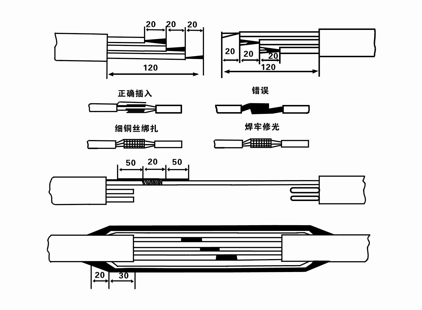
8. Använd en multimeter för att kontrollera om trefasledningarna är anslutna och om DC-resistansen är ungefär balanserad.
9. Check whether the circuit and transformer capacity are overloaded, and then connect the overload protection switch or starting equipment. See Table 2 for specific models, and then
Pour a bucket of water into the water pump from the water pump outlet to lubricate the rubber bearings in the pump, and then place the submersible electric pump upright and steady.
Start (no more than one second) and check whether the steering direction is consistent with the steering sign. If not, swap any two connectors of the three-phase cable.
Then install the filter and prepare to go down the well. If used in special occasions (such as ditches, ditches, rivers, ponds, ponds, etc.), the electric pump must be reliably grounded.
(2) Installationsutrustning och verktyg:
1. Ett par lyftkedjor för mer än två ton.
2. Ett stativ med en vertikal höjd på minst fyra meter.
3. Två hängrep (stålrep) som kan bära en vikt på mer än ett ton (kan bära vikten av en komplett uppsättning vattenpumpar).
4. Montera två par klämmor (skenor).
5. Skiftnycklar, hammare, skruvmejslar, elverktyg och instrument m.m.
(3) Installation av elektrisk pump:
1. Installationsschemat för den dränkbara elektriska pumpen visas i figur 2. De specifika installationsmåtten visas i Tabell 3 "Lista över installationsmått för den dränkbara elektriska pumpen".
2. Dränkbara elektriska pumpar med en lyfthöjd mindre än 30 meter kan hissas upp direkt i brunnen med hjälp av slangar och stållinor eller andra hamparep som kan bära hela vikten av hela maskinen, vattenledningar och vatten i rören.
3. Pumpar med en lyfthöjd på mer än 30 meter använder stålrör, och installationssekvensen är som följer:
①Use a clamp to clamp the upper end of the water pump part (the motor and water pump have been connected at this time), lift it with a hanging chain, and slowly tie it into the well until
Put the clamp on the wellhead and remove the hanging chain.
② Use another pair of clamps to clamp a pipe, lift it with a hanging chain 15 cm away from the flange, and lower it slowly. Between pipe flange and pump flange
Put the rubber pad in place and tighten the pipe and pump evenly with bolts, nuts and spring washers.
③ Lyft den dränkbara pumpen något, ta bort klämman på den övre änden av vattenpumpen, bind fast kabeln ordentligt i vattenröret med en plasttejp och fäst den långsamt tills klämman är placerad vid brunnshuvudet.
④Använd samma metod för att binda alla vattenrör i brunnen.
⑤När utledningskabeln har anslutits till kontrollomkopplaren ansluts den till trefasströmförsörjningen.
(4) Saker att notera under installationen:
1. If a jamming phenomenon is found during the pumping process, turn or pull the water pipe to overcome the jamming point. If various measures still do not work, please
Do not force the pump down to avoid damage to the submersible electric pump and the well.
2. Under installationen ska en gummikudde placeras vid flänsen på varje rör och dras åt jämnt.
3. När vattenpumpen sänks ner i brunnen ska den placeras i mitten av brunnsröret för att förhindra att pumpen löper mot brunnsväggen under lång tid, vilket får pumpen att vibrera och motorn att svepa och brinna .
4. Bestäm vattenpumpens djup till botten av brunnen enligt brunnens strömmande sand och siltförhållanden. Gräv inte ner pumpen i leran. Avståndet från vattenpumpen till botten av brunnen är i allmänhet inte mindre än 3 meter (se figur 2).
5. Vattenpumpens vatteninloppsdjup bör inte vara mindre än 1-1,5 meter från den dynamiska vattennivån till vatteninloppsnoden (se figur 2). Annars kan vattenpumpens lager lätt skadas.
6. Vattenpumpens lyftkraft får inte vara för låg. Annars måste en slussventil installeras på brunnshuvudets vattenledning för att styra pumpflödet vid den nominella flödespunkten för att förhindra att motorn överbelastas och brinner ut på grund av stora flödeshastigheter.
7. När vattenpumpen är igång ska vattenuttaget vara kontinuerligt och jämnt, strömmen ska vara stabil (under nominella arbetsförhållanden, i allmänhet inte mer än 10 % av märkströmmen), och det ska inte förekomma vibrationer eller buller. Om det finns något onormalt ska maskinen stoppas för att ta reda på orsaken och eliminera den.
8. Var uppmärksam på inställningen av motorns jordledning vid installation (se figur 2). När vattenröret är ett stålrör, led det från brunnshuvudklämman; när vattenröret är ett plaströr, led det från jordningsmärket på den elektriska pumpen.
- 1. Efter att den dränkbara pumpen har installerats, kontrollera isolationsmotståndet och trefasledningen från omkopplaren igen, kontrollera om instrumentet och anslutningen av startutrustningen är fel, om det inte är några problem kan provmaskinen startas, och observera om instrumentets indikatoravläsningar överskrider den märkspänning och ström som anges på märkskylten efter start, och observera om pumpen har brus och vibrationsfenomen, och sätt i drift om allt är normalt.
- 2. Efter den första driften av pumpen i fyra timmar bör motorn stängas av för att snabbt testa värmeisoleringsmotståndet, och dess värde bör inte vara mindre än 0,5 megaohm.
- 3. Efter att pumpen har stängts av, bör den startas efter fem minuter för att förhindra att vattenpelaren i röret återflödas helt och orsaka överdriven motorström och utbrändhet.
- 4.Efter att pumpen har satts i normal drift, för att förlänga dess livslängd, är det nödvändigt att kontrollera om matningsspänningen, arbetsströmmen och isolationsresistansen är normala regelbundet. Om följande tillstånd upptäcks, bör pumpen stängas av omedelbart för att felsöka.
- 1 In the rated condition, the current exceeds 20%.
- 2 Den dynamiska vattennivån sjunker till vatteninloppssektionen, vilket orsakar intermittent vatten.
- 3 Den dränkbara pumpen har kraftiga vibrationer eller buller.
- 4 Matningsspänningen är lägre än 340 volt.
- 5 En säkring är utbränd.
- 6 Vattenledningen är skadad.
- 7 The motor's thermal insulation resistance is lower than 0.5 megaohm.
- Unit disassembly:
- 1.Untie the cable tie, remove the pipeline part, and remove the wire plate.
- 2.screw down the water bolt, put the water in the motor chamber.
- 3.remove the filter, loose the fixed screw on the coupling to fix the motor shaft.
- 4.screw down the bolt connecting the water inlet section with the motor, and separate the pump from the motor (pay attention to the unit cushion when separating, to prevent the bending of the pump shaft)
- 5.the disassembly sequence of the pump is: (see figure 1) water inlet section, impeller, diversion shell, impeller...... check valve body, when removing the impeller, use special tools to loosen the conical sleeve of the fixed impeller first, and avoid bending and bruising the pump shaft in the process of disassembly.
- 6.the disassembly process of the motor is: (see figure 1) place the motor on the platform, and remove the nuts, base, shaft head locking nut, thrust plate, key, lower guide bearing seat and double head bolt from the bottom of the motor in turn, and then take out the rotor (pay attention not to damage the wire package) and finally remove the connecting section and upper guide bearing seat.
- 7.unit assembly: before assembly, the rust and dirt of the parts should be cleaned, and the mating surface and fasteners coated with sealant, and then assembled in the opposite order of disassembly (the motor shaft moves up and down after assembly for about one millimeter), after assembly, the coupling should be flexible, and then the filter screen test machine. Submersible pumps shall be taken out of the well for dismantling and maintenance according to Article 5 after a year of operation, or less than a year of operation but two years of diving time, and the worn parts shall be replaced.
This product is an efficient and durable submersible electric pump, suitable for a variety of environments and applications.In order to ensure the long-term use and stable performance of the product, we suggest that users pay special attention to drying the water in the motor cavity in winter to avoid freezing; in addition, the cable is coiled and tied, and properly stored in an environment without corrosive substances and gases, with a temperature below 40 °C. If the product is not used for a long time, attention should be paid to rust prevention treatment to ensure the life cycle and performance of the product.Whether for industrial use or for home use, this submersible electric pump can provide you with reliable pump service.
-
- Impeller
- Skafthylsa
- Skafthylsa av gummi
-
Tätningsring
01 Djupt brunnsvattenintag
02 Vattenförsörjning i höghus
03 bergsvattenförsörjning
04 tornet vatten
05 Jordbruksbevattning
06 trädgårdsbevattning
07 flodvattenintag
08 hushållsvatten


