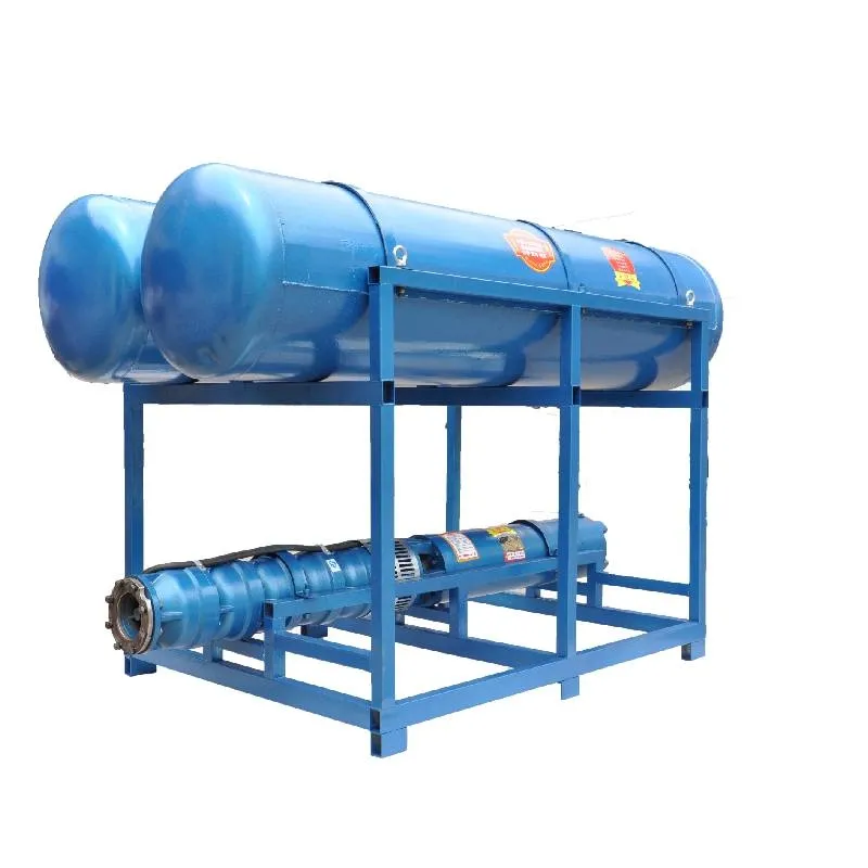
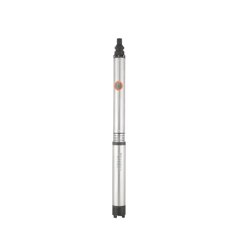
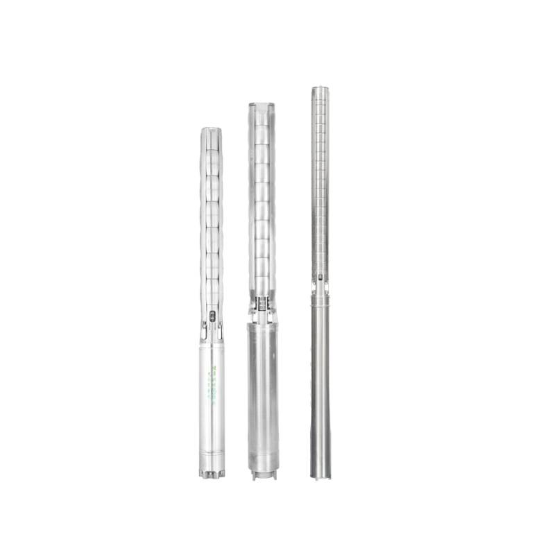
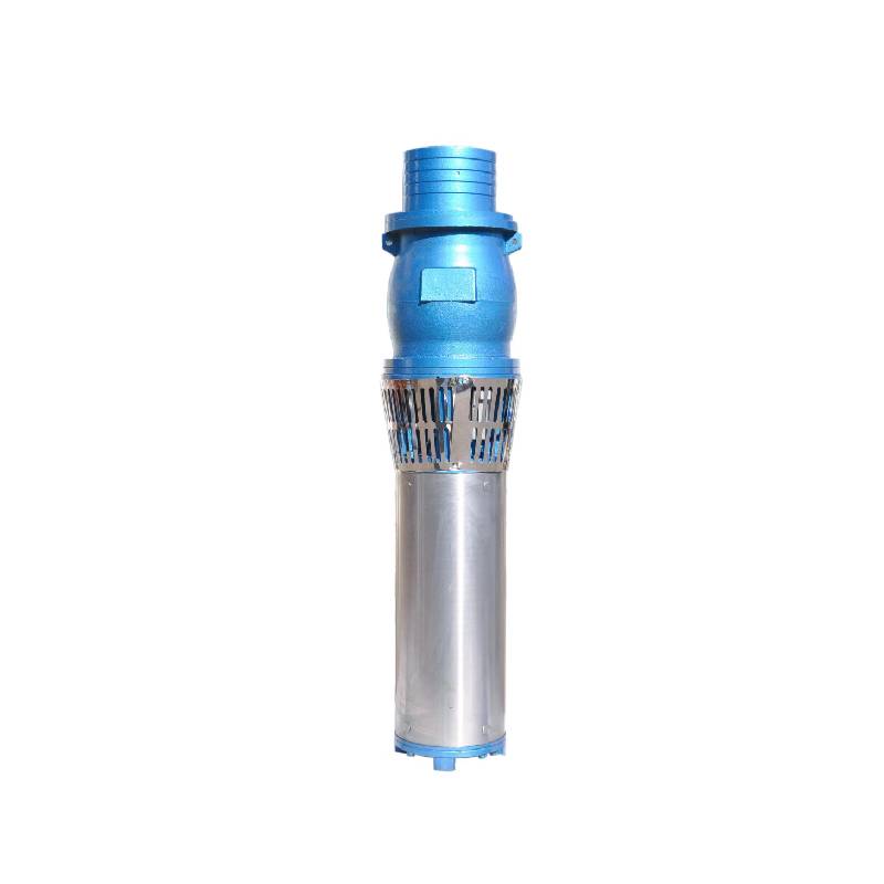
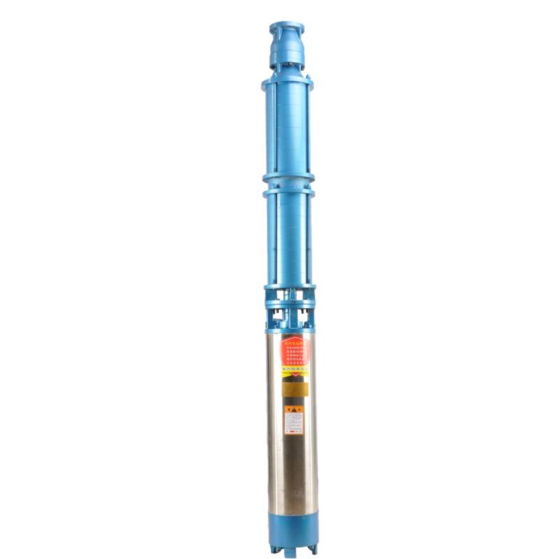
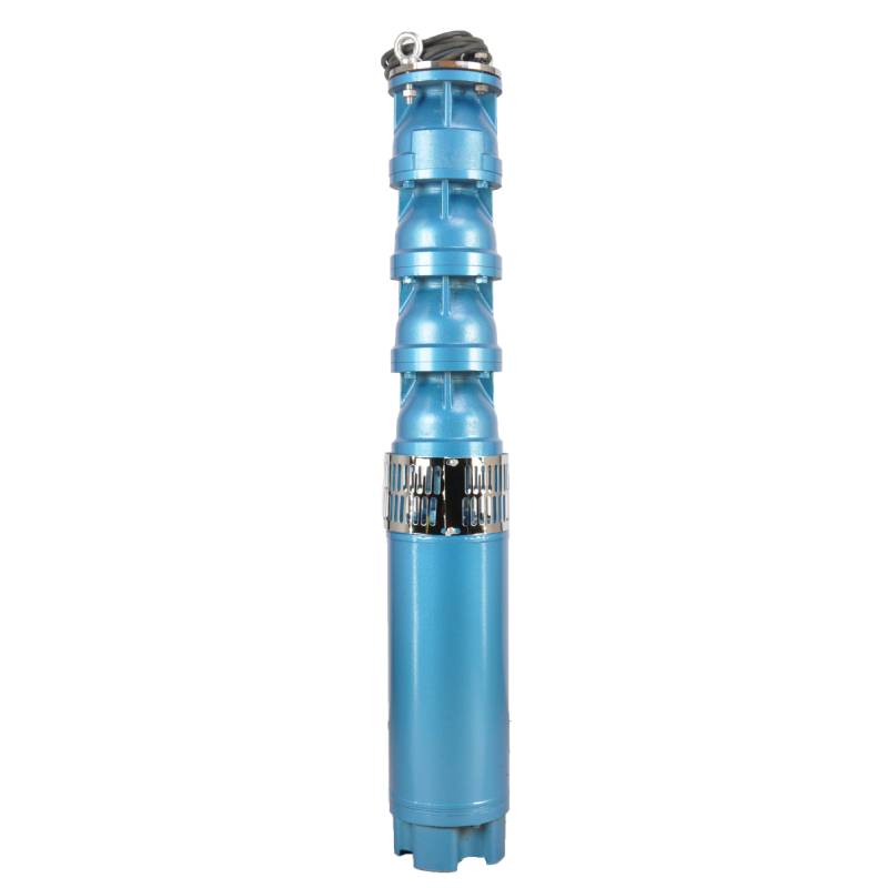
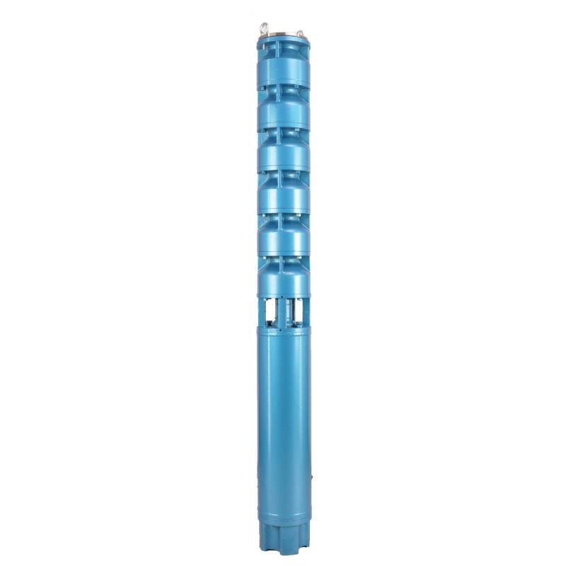
Frequency conversion winding design, ensure the motor in 1HZ-50HZ long-term stable conversion operation. Energy saving, longer service life.
1, fonte de alimentação: CA trifásica 380V (tolerância +/- 5%), 50HZ (tolerância +/- 1%).
2, qualidade da água:
(1) water temperature is not higher than 20 °C;
(2) o teor de impurezas sólidas (proporção de massa) não é superior a 0,01%;
(3) valor de PH (pH) 6,5-8,5;
(4) o teor de sulfeto de hidrogênio não é superior a 1,5mg/L;
(5) o conteúdo de íons cloreto não é superior a 400mg/L.
3, o motor está fechado ou com estrutura úmida cheia de água, antes de usar a cavidade do motor submersível deve estar cheia de água limpa, para evitar falso enchimento e, em seguida, aperte a injeção de água, parafusos de liberação de ar, caso contrário não é permitido usar
4, a bomba submersível deve estar completamente submersa na água, a profundidade de mergulho não é superior a 70m, o fundo da bomba submersível do fundo do poço não é inferior a 3m.
5, o fluxo de água do poço deve ser capaz de atender à saída de água da bomba submersível e operação contínua, a saída de água da bomba submersível deve ser controlada em 0,7 - 1,2 vezes o fluxo nominal.
6, o poço deve ser reto, a bomba submersível não pode ser usada ou despejada, apenas uso vertical.
7, a bomba submersível deve ser combinada com o cabo de acordo com os requisitos e o dispositivo de proteção contra sobrecarga externa. 8, a bomba é estritamente proibida sem máquina de teste sem carga de água
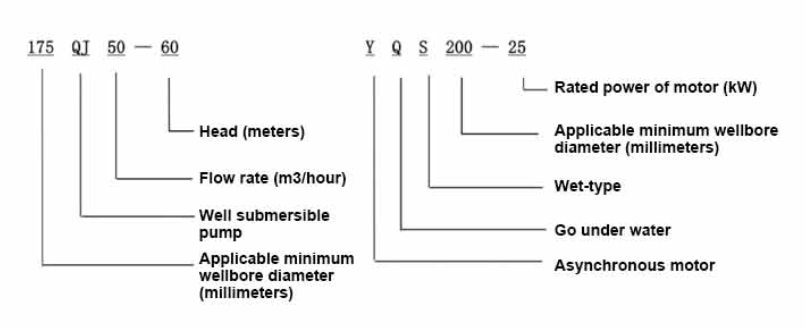
| Modelo | Fluxo (m3/h) | Cabeça (m) |
Rotating speed(change/point) | Bomba d'água (%) | Tomada diâmetro (milímetros) |
Bem aplicável diâmetro (mm) |
Avaliado potência (KW) |
Rated voltage(V) | Ratedcurrent(A) | Eficiência motora (%) | power factorcosφ | Unidade Tamanho máximo radial (mm) |
Observação | |||||||||
| 125QJ5-34 | 5 | 34 | 2850 | 53 | 40 | 125acima | 1.5 | 380 | 4.23 | 70.0 | 0.77 | 118 | ||||||||||
| 125QJ5-51 | 51 | 2.2 | 6.03 | 72.0 | 0.77 | |||||||||||||||||
| 125QJ5-68 | 68 | 3 | 8.01 | 73.0 | 0.78 | |||||||||||||||||
| 125QJ5-85 | 85 | 4 | 10.53 | 74.0 | 0.78 | |||||||||||||||||
| 125QJ5-102 | 102 | 5.5 | 14.1 | 75.0 | 0.79 | |||||||||||||||||
| 125QJ5-119 | 119 | 5.5 | 14.1 | 75.0 | 0.79 | |||||||||||||||||
| 125QJ10-24 | 10 | 24 | 2850 | 60 | 50 | 125acima | 1.5 | 380 | 4.23 | 70.0 | 0.77 | 118 | ||||||||||
| 125QJ10-32 | 32 | 2.2 | 6.03 | 72.0 | 0.77 | |||||||||||||||||
| 125QJ10-48 | 48 | 3 | 8.01 | 73.0 | 0.78 | |||||||||||||||||
| 125QJ10-56 | 56 | 4 | 10.53 | 74.0 | 0.78 | |||||||||||||||||
| 125QJ10-72 | 72 | 5.5 | 14.1 | 75.0 | 0.79 | |||||||||||||||||
| 125QJ10-80 | 80 | 5.5 | 14.1 | 75.0 | 0.79 | |||||||||||||||||
| 125QJ10-104 | 104 | 7.5 | 19.0 | 76.0 | 0.79 | |||||||||||||||||
| 125QJ10-120 | 10 | 120 | 2850 | 60 | 50 | 125acima | 7.5 | 380 | 19.0 | 76.0 | 0.79 | 118 | ||||||||||
| 125QJ10-136 | 136 | 9.2 | 22.7 | 77.0 | 0.8 | |||||||||||||||||
| 125QJ15-36 | 15 | 36 | 2850 | 63 | 50 | 125acima | 2.2 | 380 | 6.03 | 72.0 | 0.77 | 118 | ||||||||||
| 125QJ15-39 | 39 | 3 | 8.01 | 73.0 | 0.78 | |||||||||||||||||
| 125QJ15-46 | 46 | 4 | 10.53 | 74.0 | 0.78 | |||||||||||||||||
| 125QJ15-52 | 52 | 4 | 10.53 | 74.0 | 0.78 | |||||||||||||||||
| 125QJ15-59 | 59 | 5.5 | 14.1 | 75.0 | 0.79 | |||||||||||||||||
| 125QJ15-65 | 65 | 5.5 | 14.1 | 75.0 | 0.79 | |||||||||||||||||
| 125QJ15-78 | 78 | 7.5 | 19.0 | 76.0 | 0.79 | |||||||||||||||||
| 125QJ15-91 | 91 | 7.5 | 19.0 | 76.0 | 0.79 | |||||||||||||||||
| 125QJ15-104 | 104 | 9.2 | 22.7 | 77.0 | 0.8 | |||||||||||||||||
| 125QJ20-16 | 20 | 16 | 2850 | 64 | 50 | 125acima | 2.2 | 380 | 6.03 | 72.0 | 0.77 | 118 | ||||||||||
| 125QJ20-24 | 24 | 3 | 8.01 | 73.0 | 0.78 | |||||||||||||||||
| 125QJ20-32 | 32 | 4 | 10.53 | 74.0 | 0.78 | |||||||||||||||||
| 125QJ20-40 | 40 | 4 | 10.53 | 74.0 | 0.78 | |||||||||||||||||
| 125QJ20-48 | 48 | 5.5 | 14.1 | 75.0 | 0.79 | |||||||||||||||||
| 125QJ20-56 | 56 | 5.5 | 14.1 | 75.0 | 0.79 | |||||||||||||||||
| 125QJ20-64 | 64 | 7.5 | 19.0 | 76.0 | 0.79 | |||||||||||||||||
| 125QJ20-72 | 72 | 7.5 | 19.0 | 76.0 | 0.79 | |||||||||||||||||
| 125QJ20-80 | 80 | 9.2 | 22.7 | 77.0 | 0.8 | |||||||||||||||||
| 125QJ25-12 | 25 | 12 | 2850 | 64 | 65 | 125acima | 2.2 | 380 | 6.03 | 72.0 | 0.77 | 118 | ||||||||||
| 125QJ25-18 | 18 | 3 | 8.01 | 73.0 | 0.78 | |||||||||||||||||
| 125QJ25-24 | 24 | 4 | 10.53 | 74.0 | 0.78 | |||||||||||||||||
| 125QJ25-30 | 30 | 4 | 10.53 | 74.0 | 0.78 | |||||||||||||||||
| 125QJ25-36 | 36 | 5.5 | 14.1 | 75.0 | 0.79 | |||||||||||||||||
| 125QJ25-48 | 48 | 7.5 | 19.0 | 76.0 | 0.79 | |||||||||||||||||
| 125QJ25-60 | 60 | 9.2 | 22.7 | 77.0 | 0.8 | |||||||||||||||||
| 125QJ32-24 | 32 | 24 | 2850 | 64 | 80 | 125acima | 4 | 380 | 10.53 | 74.0 | 0.78 | 118 | ||||||||||
| 125QJ32-30 | 30 | 5.5 | 14.1 | 75.0 | 0.79 | |||||||||||||||||
| 125QJ32-42 | 42 | 7.5 | 19.0 | 76.0 | 0.79 | |||||||||||||||||
| 125QJ32-54 | 54 | 9.2 | 22.7 | 77.0 | 0.8 | |||||||||||||||||
| 125QJ5-240 | 5 | 240 | 2850 | 40 | 125acima | 11 | 380 | 26.28 | 118 | |||||||||||||
| 125QJ5-280 | 280 | 13 | 30.87 | |||||||||||||||||||
| 125QJ5-320 | 320 | 15 | 35.62 | |||||||||||||||||||
| 125QJ10-180 | 10 | 180 | 2850 | 50 | 125acima | 11 | 380 | 26.28 | 118 | |||||||||||||
| 125QJ10-210 | 210 | 13 | 30.87 | |||||||||||||||||||
| 125QJ10-240 | 240 | 15 | 35.62 | |||||||||||||||||||
| 125QJ15-120 | 15 | 120 | 2850 | 50 | 125acima | 11 | 380 | 26.28 | 118 | |||||||||||||
| 125QJ15-142 | 142 | 13 | 30.87 | |||||||||||||||||||
| 125QJ15-162 | 162 | 15 | 35.62 | |||||||||||||||||||
| 125QJ20-100 | 20 | 100 | 2850 | 50 | 125acima | 11 | 380 | 26.28 | 118 | |||||||||||||
| 125QJ20-120 | 120 | 13 | 30.87 | |||||||||||||||||||
| 125QJ20-136 | 136 | 15 | 35.62 | |||||||||||||||||||
| 125QJ25-82 | 25 | 82 | 2850 | 65 | 125acima | 11 | 380 | 26.28 | 118 | |||||||||||||
| 125QJ25-97 | 97 | 13 | 30.87 | |||||||||||||||||||
| 125QJ25-110 | 110 | 15 | 35.62 | |||||||||||||||||||
| 125QJ32-68 | 32 | 68 | 2850 | 80 | 125acima | 11 | 380 | 26.28 | 118 | |||||||||||||
| 125QJ32-80 | 80 | 13 | 30.87 | |||||||||||||||||||
| 125QJ32-92 | 92 | 15 | 35.62 | |||||||||||||||||||
| 125QJ40-46 | 40 | 46 | 2850 | 80 | 125acima | 11 | 380 | 26.28 | 118 | |||||||||||||
| 125QJ40-54 | 54 | 13 | 30.87 | |||||||||||||||||||
| 125QJ40-62 | 62 | 15 | 35.62 | |||||||||||||||||||
The well submersible pump is a pump suitable for clear water. It is strictly prohibited to dig new wells and pump out mud and sand. The voltage grade of the well pump is 380V/50HZ, and other voltage grades of the submersible motor need to be customized. Underground cables must be waterproof cables and must be equipped with starting equipment, such as distribution box, etc. The starting equipment should have common motor comprehensive protection functions, such as short circuit overload protection, phase loss protection, undervoltage protection, grounding protection and idling protection, etc. In abnormal cases, the protective device should be tripped in time. When installing and using the pump, it must be firmly grounded. It is prohibited to push and pull the switch when the hands and feet are wet. The power supply must be cut off before installing and maintaining the pump. An obvious "anti-electric shock" sign must be set up where the pump is used. Before going down the well or installing the motor, the inner cavity must be filled with distilled water or non-corrosive clean cold water, and the water injection/drainage bolts must be tightened. Fill the pump with water for ground test to lubricate the rubber bearings. The instant start time shall not exceed one second to check whether the direction is correct and consistent with the direction indication. Be sure to pay attention to safety when placing the pump upright to prevent overturning and causing injury. Strictly in accordance with the provisions of the pump lift and flow range of use, to prevent the pump flow at low lift or excessive pull at high lift, resulting in extreme wear of thrust bearings and other components, resulting in motor overload burn. After the pump into the well, the insulation resistance between the motor and the ground shall be measured, which shall not be less than 100MΩ. After the start, observe the voltage and current regularly, and check the motor winding insulation, to see if it meets the requirements; if the pump storage temperature is below the freezing point, the water in the motor cavity should be discharged, so as to avoid the water in the motor cavity freezing and damaging the motor due to low temperature.
As principais características do produto incluem:
1.The motor is a water-loaded wet submersible three-phase asynchronous motor,and the motor cavity is filled with clean water for cooling the motor and lubricating the bearing.The regulating diaphragm at the bottom of the motor is used to adjust the expansion and contraction pressure difference inside and outside the body caused by the temperature rise of the motor.
2.In order to prevent the sand particles in the well water from entering the motor,two oil seals are installed at the extension end of the motor shaft,and the sand ring is installed to form a sand prevention structure.
3.In order to prevent the pump shaft from jumping when starting,the pump shaft is connected with the motor shaft through a coupling,and the thrust bearing is installed at the bottom of the motor.
4.The lubrication of the motor and the pump bearing is water lubrication.
5.The stator winding of the motor adopts high-quality submersible motor winding wire,with excellent insulation performance.
6.The pump is designed by computer CAD,with simple structure and excellent technical performance.

(1)Preparação antes da instalação:
1. Verifique se a bomba submersível atende às condições de uso e escopo especificados no manual.
2. Usando um objeto pesado com diâmetro igual ao diâmetro externo máximo da bomba submersível, meça se o diâmetro interno do poço pode caber na bomba submersível e meça se a profundidade do poço atende aos requisitos de instalação.
3. Verifique se o poço está limpo e se a água do poço está turva. Nunca use uma bomba elétrica submersível para lavar a lama da bomba Welor e água de areia para evitar danos prematuros à bomba elétrica submersível.
4. Verifique se a posição da braçadeira de instalação da cabeça de poço é adequada e se ela pode suportar a qualidade de toda a unidade
5. Verifique se os componentes da bomba submersível estão completos e instalados corretamente de acordo com o diagrama de montagem no manualRemova a tela do filtro e gire o acoplamento para ver se ele gira de forma flexível
6. Desaparafuse o parafuso de água e encha a cavidade do motor com água limpa e não corrosiva (nota: certifique-se de enchê-la) e, em seguida, aperte o parafuso de água. Após 12 horas de injeção de água, a resistência de isolamento do motor não deve ser inferior a 150M Q quando medida com uma mesa vibratória de 500V.
7. Cable joint, cut off a 120mm rubber sleeve from one end of the outgoing cable and the matching cable with an electrician's knifethen stagger the length of the three core wires in a stepped shape, peel off a 20mm copper core, scrape of the oxide layer on theoutside of the copper wire with a knife or sand cloth, and insert the two connected wire ends in palirs.
After tying the layer tightly with fine copper wire, solder it thoroughly and firmly, and sand of any. burrs on the surface. Then, forthe three joints, use polyvester insulation tape to wrap them in a semi stacked manner for three lavers. Wrap the two ends of thewrapping layer tightywith nyion thread,and then use a semi stacked method to wrap the tape for three layers. Wrap the outellayer with high-pressure insulation tape for three layers. Finally, fold the threestrands together and repeatedly wrap them for fivelayers with high-pressure tape. Each layer must be tightly tied, and the interlayer joints must be tight and fimm to prevent water frompenetrating and damaging the insulation, After wrapping, soak in water at room temperature of 20 ’c for 12 hours, and measurethe insulation resistance with a shaking table, which should not be less than 100M Ω
O diagrama do processo de fiação do cabo anexado é o seguinte:
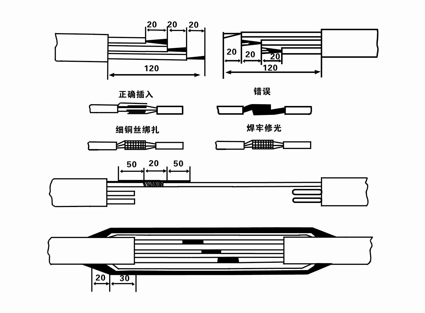
8. Use um multímetro para verificar se os fios trifásicos estão conectados e se a resistência CC está aproximadamente equilibrada.
9. Check whether the circuit and transformer capacity are overloaded, and then connect the overload protection switch or starting equipment. See Table 2 for specific models, and then
Pour a bucket of water into the water pump from the water pump outlet to lubricate the rubber bearings in the pump, and then place the submersible electric pump upright and steady.
Start (no more than one second) and check whether the steering direction is consistent with the steering sign. If not, swap any two connectors of the three-phase cable.
Then install the filter and prepare to go down the well. If used in special occasions (such as ditches, ditches, rivers, ponds, ponds, etc.), the electric pump must be reliably grounded.
(2) Equipamentos e ferramentas de instalação:
1. Um par de correntes de elevação para mais de duas toneladas.
2. Um tripé com altura vertical não inferior a quatro metros.
3. Duas cordas suspensas (cabos de aço) que podem suportar um peso de mais de uma tonelada (podem suportar o peso de um conjunto completo de bombas d'água).
4. Instale dois pares de grampos (talas).
5. Chaves, martelos, chaves de fenda, ferramentas e instrumentos elétricos, etc.
(3)Instalação da bomba elétrica:
1. O diagrama de instalação da bomba elétrica submersível é mostrado na Figura 2. As dimensões específicas de instalação são mostradas na Tabela 3 “Lista de Dimensões de Instalação da Bomba Elétrica Submersível”.
2. Bombas elétricas submersíveis com altura manométrica inferior a 30 metros podem ser içadas diretamente para o poço usando mangueiras e cabos de aço ou outras cordas de cânhamo que possam suportar o peso total de toda a máquina, canos de água e água nos canos.
3. As bombas com altura manométrica superior a 30 metros utilizam tubos de aço e a sequência de instalação é a seguinte:
①Use a clamp to clamp the upper end of the water pump part (the motor and water pump have been connected at this time), lift it with a hanging chain, and slowly tie it into the well until
Put the clamp on the wellhead and remove the hanging chain.
② Use another pair of clamps to clamp a pipe, lift it with a hanging chain 15 cm away from the flange, and lower it slowly. Between pipe flange and pump flange
Put the rubber pad in place and tighten the pipe and pump evenly with bolts, nuts and spring washers.
③ Levante ligeiramente a bomba submersível, remova a braçadeira na extremidade superior da bomba d'água, amarre o cabo firmemente ao tubo de água com uma fita plástica e amarre-o lentamente até que a braçadeira seja colocada na cabeça do poço.
④Use o mesmo método para amarrar todos os canos de água ao poço.
⑤Depois que o cabo de saída é conectado à chave de controle, ele é conectado à fonte de alimentação trifásica.
(4)Observações durante a instalação:
1. If a jamming phenomenon is found during the pumping process, turn or pull the water pipe to overcome the jamming point. If various measures still do not work, please
Do not force the pump down to avoid damage to the submersible electric pump and the well.
2. Durante a instalação, uma almofada de borracha deve ser colocada no flange de cada tubo e apertada uniformemente.
3. Quando a bomba de água é abaixada no poço, ela deve ser colocada no meio do tubo do poço para evitar que a bomba funcione contra a parede do poço por um longo tempo, fazendo com que a bomba vibre e o motor varra e queime .
4. Determine a profundidade da bomba d'água até o fundo do poço de acordo com o fluxo de areia e lodo do poço. Não enterre a bomba na lama. A distância da bomba de água ao fundo do poço geralmente não é inferior a 3 metros (ver Figura 2).
5. A profundidade de entrada de água da bomba de água não deve ser inferior a 1-1,5 metros do nível dinâmico de água até o nó de entrada de água (ver Figura 2). Caso contrário, os rolamentos da bomba de água podem ser facilmente danificados.
6. A elevação da bomba d'água não pode ser muito baixa. Caso contrário, uma válvula gaveta precisa ser instalada na tubulação de água da cabeça do poço para controlar o fluxo da bomba no ponto de fluxo nominal para evitar que o motor fique sobrecarregado e queime devido a grandes vazões.
7. Quando a bomba de água está funcionando, a saída de água deve ser contínua e uniforme, a corrente deve ser estável (sob condições nominais de trabalho, geralmente não mais que 10% da corrente nominal) e não deve haver vibração ou ruído. Se houver alguma anormalidade, a máquina deve ser parada para descobrir a causa e eliminá-la.
8. Ao instalar preste atenção ao ajuste do fio terra do motor (ver Figura 2). Quando o cano de água for de aço, conduza-o pela braçadeira da cabeça do poço; quando a tubulação de água for de plástico, conduza-a a partir da marca de aterramento da bomba elétrica.
- 1. Após a instalação da bomba submersível, verifique novamente a resistência de isolamento e a condução trifásica do interruptor, verifique se o instrumento e a conexão do equipamento de partida estão errados, se não houver problema, a máquina de teste pode ser iniciada, e observe se as leituras do indicador do instrumento excedem a tensão e corrente nominais especificadas na placa de identificação após a partida, e observe se a bomba apresenta fenômeno de ruído e vibração, e coloque em operação se tudo estiver normal.
- 2.Após a primeira operação da bomba por quatro horas, o motor deve ser desligado para testar rapidamente a resistência do isolamento térmico, e seu valor não deve ser inferior a 0,5 megaohm.
- 3.Depois que a bomba for desligada, ela deve ser iniciada após cinco minutos para evitar que a coluna de água no tubo seja completamente refluída e cause corrente excessiva do motor e queima.
- 4.Depois que a bomba for colocada em operação normal, para prolongar sua vida útil, é necessário verificar regularmente se a tensão de alimentação, a corrente de trabalho e a resistência de isolamento estão normais. Se as seguintes condições forem encontradas, a bomba deverá ser desligada imediatamente para solução de problemas.
- 1 In the rated condition, the current exceeds 20%.
- 2 O nível dinâmico da água cai para a seção de entrada de água, causando água intermitente.
- 3 A bomba submersível apresenta vibração ou ruído intenso.
- 4 A tensão de alimentação é inferior a 340 volts.
- 5 Um fusível está queimado.
- 6 O tubo de abastecimento de água está danificado.
- 7 The motor's thermal insulation resistance is lower than 0.5 megaohm.
- Unit disassembly:
- 1.Untie the cable tie, remove the pipeline part, and remove the wire plate.
- 2.screw down the water bolt, put the water in the motor chamber.
- 3.remove the filter, loose the fixed screw on the coupling to fix the motor shaft.
- 4.screw down the bolt connecting the water inlet section with the motor, and separate the pump from the motor (pay attention to the unit cushion when separating, to prevent the bending of the pump shaft)
- 5.the disassembly sequence of the pump is: (see figure 1) water inlet section, impeller, diversion shell, impeller...... check valve body, when removing the impeller, use special tools to loosen the conical sleeve of the fixed impeller first, and avoid bending and bruising the pump shaft in the process of disassembly.
- 6.the disassembly process of the motor is: (see figure 1) place the motor on the platform, and remove the nuts, base, shaft head locking nut, thrust plate, key, lower guide bearing seat and double head bolt from the bottom of the motor in turn, and then take out the rotor (pay attention not to damage the wire package) and finally remove the connecting section and upper guide bearing seat.
- 7.unit assembly: before assembly, the rust and dirt of the parts should be cleaned, and the mating surface and fasteners coated with sealant, and then assembled in the opposite order of disassembly (the motor shaft moves up and down after assembly for about one millimeter), after assembly, the coupling should be flexible, and then the filter screen test machine. Submersible pumps shall be taken out of the well for dismantling and maintenance according to Article 5 after a year of operation, or less than a year of operation but two years of diving time, and the worn parts shall be replaced.
This product is an efficient and durable submersible electric pump, suitable for a variety of environments and applications.In order to ensure the long-term use and stable performance of the product, we suggest that users pay special attention to drying the water in the motor cavity in winter to avoid freezing; in addition, the cable is coiled and tied, and properly stored in an environment without corrosive substances and gases, with a temperature below 40 °C. If the product is not used for a long time, attention should be paid to rust prevention treatment to ensure the life cycle and performance of the product.Whether for industrial use or for home use, this submersible electric pump can provide you with reliable pump service.
-
- Impulsor
- Manga do eixo
- Luva do eixo de borracha
-
Anel de vedação
01 Tomada de água de poço profundo
02 Abastecimento de água em arranha-céus
03 abastecimento de água na montanha
04 torre de água
05 Irrigação agrícola
06 irrigação de jardim
07 captação de água do rio
08 água doméstica


